Page 240 of 391

_-
21-16AUTOMATIC TRANSAXLE - General InformationAUTOMATIC
TRANSAXLE
GENERAL INFQRMATIONRzlBBACF4A22 automatic transaxles with different shift pattern are introduced to match engine output characteristics.
These F4A22 automatic transaxles are transaxles of KM1 70 Type II series and each is a two-mode
electronically controlled automatic transaxle with shift patterns of two modes.
SPECIFICATIONS
Items
Transaxle modelTorque convertor
Me
Stall torque ratio
TransaxleType
Gear ratio
1 St
2nd
3rd4th
ReversePrimary reduction ratio
Differential gear ratio
Friction elements
Number of front clutch discs
Number of rear clutch discs
Number of end clutch discs
Number of low/reverse brake discs
Number of
kickdown brake bandControl system
Manual control system
Shift pattern type
Solenoid yalve operationShift control
(2)
Pressure control
Damper clutch controlDiagnosis
Indication method
Number of diagnosis items
Speedometer gear ratio
ATFOil quantityliter
(qts.)
Specifications-4A22-2-MPAl3element, 1 -stage,
2-phase with damper clutch
2.17l-speed forward, l-speed reverse
2.846
1.581
1
.ooo
3.685
2.176
1.125
3.611V&N-D-2-L (lever type) with overdrive switch
Two-mode electronic-hydraulic control type
ON-OFF controlDuty control
Duty control
Indication with
LEDs
24
29136
MOPAR ATF PLUS (AUTOMATIC TRANSMISSIOI
FLUID TYPE 7176VAutomatic Transmission Fluid“DEXRON” or “DEXRON II”
\I6.1
(6.4)J
Page 250 of 391
21-26AUTOMATIC TRANSAXLE - Transaxle Mechanism
REAR CLUTCH
Wave sprmgRear clutch retainer
Clutch reaction piateClutch pressure plate
I1rao2l5Rear clutch is of the multiple disc type, and is
composed of a rear clutch retainer, disc, plates, and
a piston. When the piston is actuated by the oil
pressure, the multiple disc clutch is connected,
conveying driving force from the input shaft to the
forward sun gear in the planetary gear set. The rear
clutch is always actuated when the shift is in first,
second and third gears.
INumber of clutch discsI.3I
1 Number of clutch piates1 2 I-
I Number of reaction plates
I
1 1
I Number of pressure plates’I 1 I
PistonO.D.mm (in.)121 (4.761
I.D.mm (in.)36 (1.42)
POWER FLOW
Rear clutch
Rear clutch hubRear clutch retainer
Forward sun gear,
IInput shaftRear clutch retainerRear clutchRear clutch hubForward sun gear
Page 267 of 391

AUTOMATIC TRANSAXLE - Transaxle Control21-43
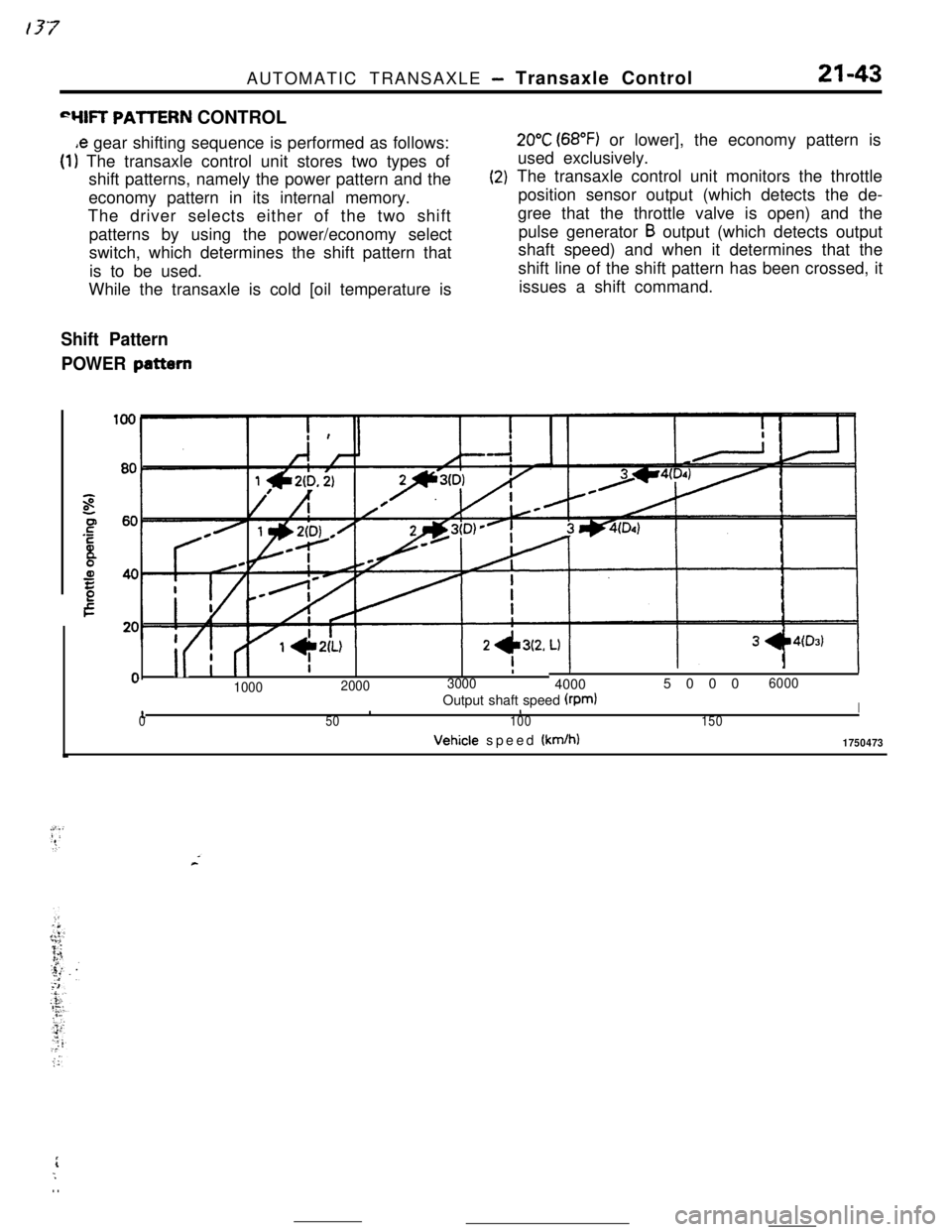
“YIR PAllERN CONTROL
,e gear shifting sequence is performed as follows:
(1) The transaxle control unit stores two types of
shift patterns, namely the power pattern and the
economy pattern in its internal memory.
The driver selects either of the two shift
patterns by using the power/economy select
switch, which determines the shift pattern that
is to be used.
While the transaxle is cold [oil temperature is
(2)
Shift Pattern
POWER
pattern
20°C (68°F) or lower], the economy pattern is
used exclusively.
The transaxle control unit monitors the throttle
position sensor output (which detects the de-
gree that the throttle valve is open) and the
pulse generator
B output (which detects output
shaft speed) and when it determines that the
shift line of the shift pattern has been crossed, it
issues a shift command.
i
II I (I
I -L\LI1- --‘-0
II
0I
100020003000
II400050006000
10Output shaft speed (rpmlIII50100150Vehicle speed
(km/h)1750473
rL;. .
Page 274 of 391

21-50AUTOMATIC TRANSAXLE - Transaxle Control
Vehicle
sensorspeedTerminal voltage
(VI
1
5
\*Fluidtemperature
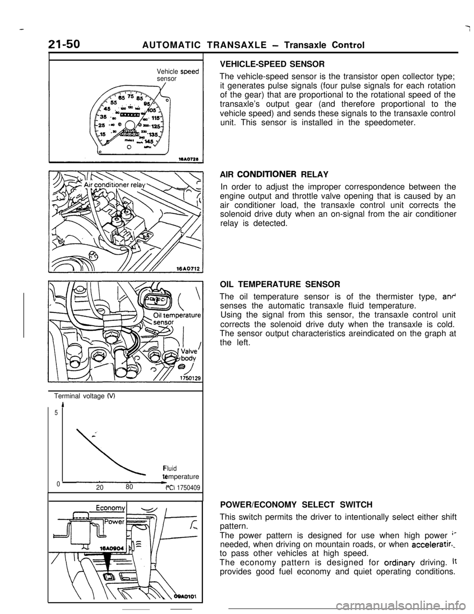
02080PCI 1750409VEHICLE-SPEED SENSOR
The vehicle-speed sensor is the transistor open collector type;
it generates pulse signals (four pulse signals for each rotation
of the gear) that are proportional to the rotational speed of the
transaxle’s output gear (and therefore proportional to the
vehicle speed) and sends these signals to the transaxle control
unit. This sensor is installed in the speedometer.
AIR CONDlTlONER RELAY
In order to adjust the improper correspondence between the
engine output and throttle valve opening that is caused by an
air conditioner load, the transaxle control unit corrects the
solenoid drive duty when an on-signal from the air conditioner
relay is detected.
OIL TEMPERATURE SENSOR
The oil temperature sensor is of the thermister type,
an+senses the automatic transaxle fluid temperature.
Using the signal from this sensor, the transaxle control unit
corrects the solenoid drive duty when the transaxle is cold.
The sensor output characteristics areindicated on the graph at
the left.
POWER/ECONOMY SELECT SWITCH
This switch permits the driver to intentionally select either shift
pattern.
The power pattern is designed for use when high power
‘*needed, when driving on mountain roads, or when acceleratirl,
to pass other vehicles at high speed.
The economy pattern is designed for ordinan/ driving.
ltprovides good fuel economy and quiet operating conditions.
Page 279 of 391
AUTOMATIC TRANSAXLE - Transaxle Control21-55HYDRAULIC CONTROL SYSTEM
Reaction shaft
support
BushingThe hydraulic control system consists of an oil pump which
generates hydraulic pressure for the system, and valves and
solenoid valves to control the pressure or switch the oil
passages. The valves and solenoid valves are all built in the
valve body.
OIL PUMPOil pump generates the pressure for supplying oil to the torque
converter, for lubricating frictional parts of the planetary gear
set and the overrunning clutch, etc., and for activating the
hydraulic control system.
The pump is of the inner-teeth engaging involute gear type. It
always generates the oil pressure when the engine is running
since the drive gear
is driven by 2 pawls of the pump drive hub
welded at the center of the torque converter shell.