Page 202 of 391
_ -. ..__ .-
REAR SUSPENSION
<4WD> - Geneal (nformation
THREE SIDE VIEWS
Trailil
12AOll
SPECiFiCATiONSItems
Suspension system
Coil springWire dia. x O.D.
x free lengthmm (in.)Coil spring identification
colourSpring constantN/mm
(kg/mm. Ibs.An.1
Shock absorberType
Max. lengthmm
(in.)Min. length
mm (in.)Stroke
mm (in.)
Damping force (at 0.3
m/set. (0.9 ft./sec.)l
Expansion
N (kg. Ibs.)Contraction
N (kg, Ibs.)Wheel alignment
Toe-in (left/right wheel difference)mm (in.)
CamberSpecifications
Double wishbone tvpe
11.0x106x332.5(.43x4.17x13.1)
Purple x 125.0
(2.50, 140)Hydraulic, cylindrical double-acting
We
568 (22.4)380
(15.0)
188 (7.4)900
(90. 198)300
(30.66)3.6
f 3 (.14 2 .I21
-1”33’ + 30’
Page 207 of 391
17-14REAR SUSPENSION - Double Wishbone Suwension
REAR SHOCK ABSORBERThe rear shock absorber consists of a shock
absorber, coil spring, etc., arranged concentrically.
The shock absorber is a hydraulic cylinder of the
double action type with low sliding resistance, and
gives stable damping force.The inputs from the shock absorber and coil
spr,are borne by the upper bushings and spring pad,
respectively, for a better ride and lower vibration
and noise level. A polyurethane foam bump rubber
has been adopted for effective shock absorption in
the event of completely bottoming out.
Cap ,-&
Upper bushing A _
IlXk!! \Upper bushing Bx?nb
Spring padBump rubber
Page 211 of 391
19-2 POWER STEERING
Rlh
integral rack and pinion type. This power steering
oear and the oil reservoir for effective cooling of
Fhe power steering fluid.The steering gear box is of a compact, light-weight
Steering
SYJo& assembly
oil pump
\Pressure hose
A
Page 212 of 391
POWER STEERING- General Information19-3
SPEClFlCATlONSItems
Steering wheel O.D.
mm (in.)Steering wheel maximum turns
Shaft and joint type
Steering angleInner wheel
Outer wheel
Tilt strokemm
(in.1Steering gear type
Rack strokemm (in.)Oil pump type
Oil pump displacement
cm3/rev. (cu.in./rev.)Specifications
372
(14.6)
2.7
Collapsible, cross joints (two joints used)
35”OO’ + 2”
29”20’
30
(1.2)
Rack and pinion
138
(5.41
Vane type9.6
l.59)
Page 214 of 391
.-. --POWER STEERING
- Power Steering Gear Box Construction19-5
-POWER STEERING GEAR BOX CONSTRUCTIONRlsJLIIUB,
ne steering gear box is of the rack and pinion type
with a built-in hydraulic control unit which uses a
compact and highly reliable rotary valve.The steering gear box, in the same way as the
manual steering gear box, is installed to the body by
way of the mounting rubber in order to reduce the
transmission of vibrations.
Section A-A
Beari
1-$ysy input shaft
To oilreservoir
LFrom oil
I’Rotary valve
Yoke spring
13A0257
Section B-B
From oil pumpTo oil reservoir
To cylinder tubeleft chamber
To cylinder tube
13A0077right chamber
Page 219 of 391

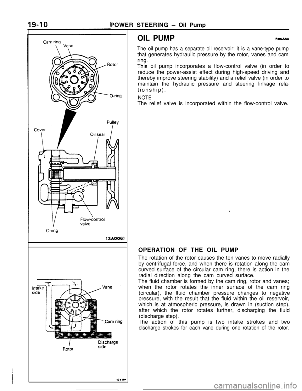
POWER STEERING - Oil Pump13A0067
Insi
OIL PUMPRlUAM
The oil pump has a separate oil reservoir; it is a vane-type pumpthat generates hydraulic pressure by the rotor, vanes and cam
y”ht oil pump incorporates a flow-control valve (in order to
reduce the power-assist effect during high-speed driving and
thereby improve steering stability) and a relief valve (in order to
maintain the hydraulic pressure and steering linkage rela-
tionship).
NOTEThe relief valve is incorporated within the flow-control valve.
OPERATION OF THE OIL PUMP
The rotation of the rotor causes the ten vanes to move radially
by centrifugal force, and when there is rotation along the cam
curved surface of the circular cam ring, there is action in the
radial direction along the cam curved surface.
The fluid chamber is formed by the cam ring, rotor and vanes;
when the rotor rotates the inner surface of the cam ring
(circular), the fluid chamber pressure changes to negative
pressure, with the result that the fluid within the oil reservoir,
which is at atmospheric pressure, is drawn in (suction step),
after which the rotor rotates further, discharging the fluid
(discharge step).
The action of this pump is two intake strokes and
two
discharge strokes for each vane during one rotation of the rotor.
Page 221 of 391

POWER STEERING - Oil Pump
OIL PUMP13A0067
Insi
m-
The oil pump has a separate oil reservoir; it is a vane-type pumpthat generates hydraulic pressure by the rotor, vanes and cam
;Inhz oil pump incorporates a flow-control valve (in order to
reduce the power-assist effect during high-speed driving and
thereby improve steering stability) and a relief valve (in order to
maintain the hydraulic pressure and steering linkage rela-
tionship).
NOTEThe relief valve is incorporated within the flow-control valve.
.OPERATION OF THE OIL PUMP
The rotation of the rotor causes the ten vanes to move radially
by centrifugal force, and when there is rotation along the cam
curved surface of the circular cam ring, there is action in the
radial direction along the cam curved surface.
The fluid chamber is formed by the cam ring, rotor and vanes;
when the rotor rotates the inner surface of the cam ring
(circular), the fluid chamber pressure changes to negative
pressure, with the result that the fluid within the oil reservoir,
which is at atmospheric pressure, is drawn in (suction step),
after which the rotor rotates further, discharging the fluid
(discharge step).
The action of this pump is two intake strokes and two
discharge strokes for each vane during one rotation of the rotor.
Page 230 of 391
MANUAL TRANSAXLE <4WD> - General Information
MANUAL TRANSAXLE <4WD>
GENERAL INFORMATION
W5M33 transaxle is a transaxle for 4WD, having
center differential mounted on the output shaft ofwheels. Using the viscous coupling as a device for
the conventional front
wheeledrive type transaxle solimiting differential of the center differential, this
as to distribute drive power to the front and reartransaxle is a full time 4WD type and provides
improved traction and easy drive.
SPECIFICATIONS
Item
Transaxle model
We
Gear ratio
1 St
2nd
3rd4th5th
Reverse
Primary reduction ratio
(number of gear teeth)
Front differential gear ratio
(number of teeth)Specifications
W5M33-2-NPZS
5-speed constant-mesh cable controlled type3.083
1.684
7.1150.833
0.666
3.166
1.275 (37/29).
3.866 (58/l
51
Transfer gear ratio(number of teeth)1.090 (24/22)
Speedometer gear ratio
Oil quantity
liter (qts.)
Transaxle
Transfer
Dry weight ic kg (Ibs.)
29 I36
2.3 (2.43)0.6
(0.63)
64.0(141)