Page 144 of 391
__.-~-..- -
FUEL SYSTEM- Ermine Control Unit
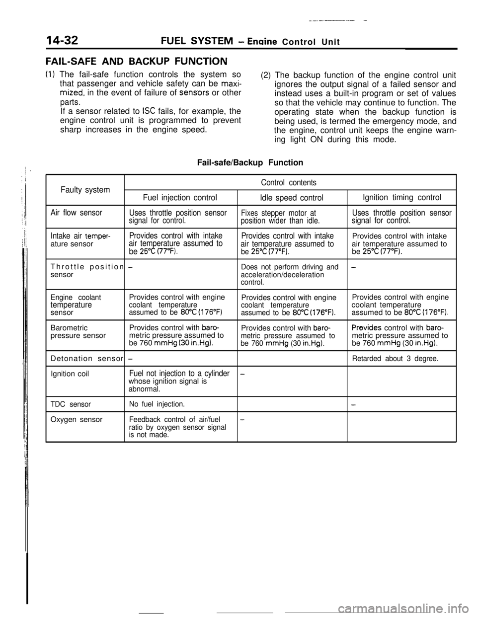
FAIL-SAFE AND BACKUP FUNCTiON
(1) The fail-safe function controls the system so
that passenger and vehicle safety can be
maxi-
mized. in the event of failure of sens.ors or other
parts.If a sensor related to
ISC fails, for example, the
engine control unit is programmed to prevent
sharp increases in the engine speed.(2) The backup function of the engine control unit
ignores the output signal of a failed sensor and
instead uses a built-in program or set of values
so that the vehicle may continue to function. The
operating state when the backup function is
being used, is termed the emergency mode, and
the engine, control unit keeps the engine warn-
ing light ON during this mode.
Fail-safe/Backup Function
Control contentsFaulty system
Fuel injection control
Idle speed controlIgnition timing control
Air flow sensor
Uses throttle position sensorFixes stepper motor atUses throttle position sensorsignal for control.
position wider than idle.signal for control.
Intake air
temper-Provides control with intake
Provides control with intakeProvides control with intake
ature sensorair temperature assumed to
be 25°C (77°F).air temperature assumed toair temperature assumed tobe 25°C (77°F).be 25°C (77°F).Throttle position
-Does not perform driving and-sensor
acceleration/deceleration
control.
Engine coolantProvides control with engine
Provides control with engineProvides control with engine
temperaturecoolant temperature
coolant temperaturecoolant temperature
sensorassumed to be 80°C (176°F)assumed to be 80°C (176°F).assumed to be 80°C (176°F).BarometricProvides control with
baro-Provides control with baro-Provides control with baro-pressure sensormetric pressure assumed to
be 760
mmHg (30 in.HgI.metric pressure assumed tometric pressure assumed tobe 760 mmHg (30 in.Hg).be 760 mmHg (30 in.Hg).Detonation sensor
-Retarded about 3 degree.Ignition coil
Fuel not injection to a cylinder-whose ignition signal is
abnormal.
TDC sensorOxygen sensor
No fuel injection.-
Feedback control of air/fuel-
ratio by oxygen sensor signal
is not made.
Page 145 of 391
FUEL SYSTEM- Fuel Injection Control14-33
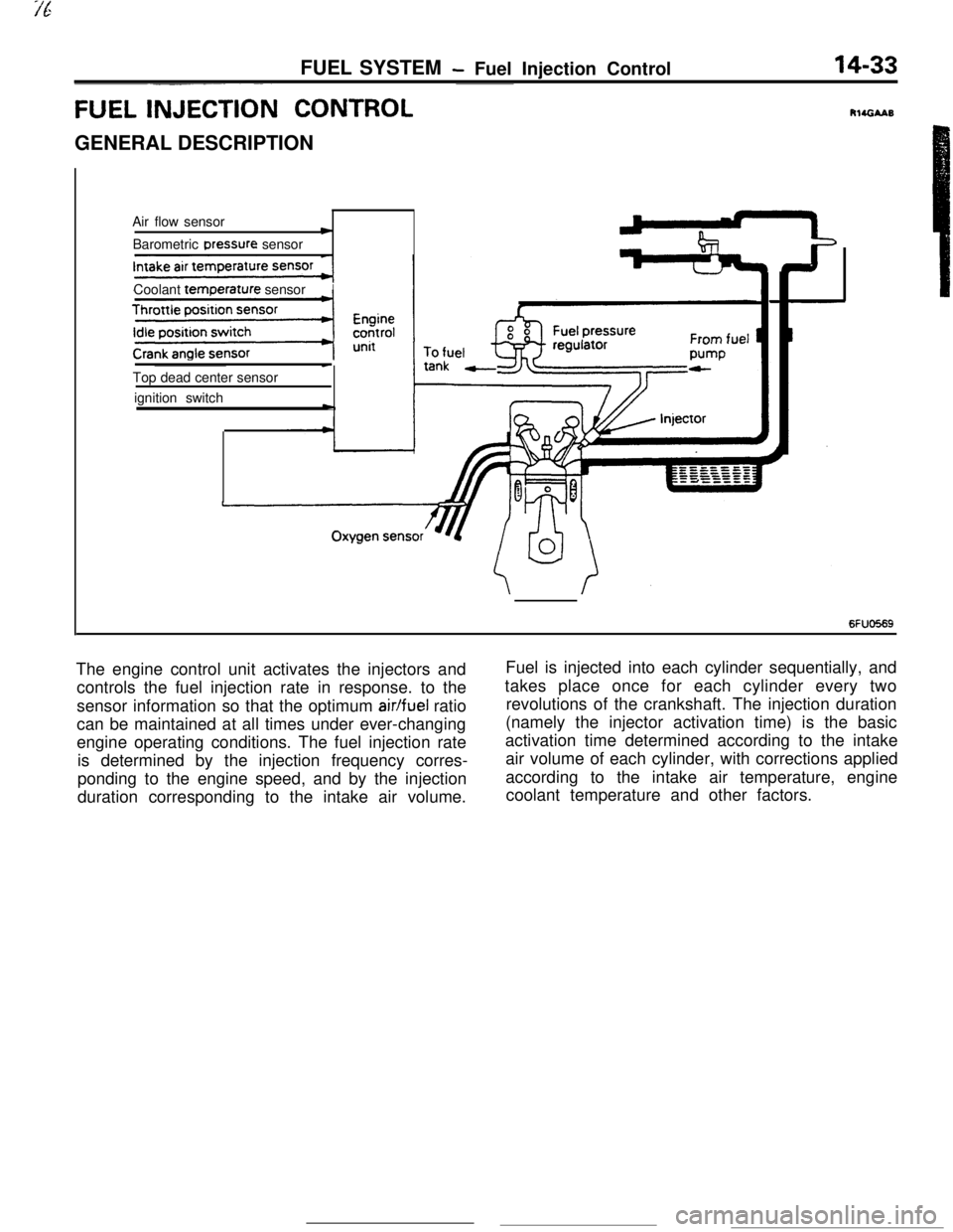
FUEL INJECTI& CONTROLGENERAL DESCRIPTION
Air flow sensor
cBarometric Dressure sensor
Coolant
temr3erature sensorITop dead center sensor
ignition switch
-
c
6FUO569The engine control unit activates the injectors andFuel is injected into each cylinder sequentially, and
controls the fuel injection rate in response. to thetakes place once for each cylinder every two
sensor information so that the optimum
air/fuel ratiorevolutions of the crankshaft. The injection duration
can be maintained at all times under ever-changing(namely the injector activation time) is the basic
engine operating conditions. The fuel injection rateactivation time determined according to the intake
is determined by the injection frequency corres-air volume of each cylinder, with corrections applied
ponding to the engine speed, and by the injectionaccording to the intake air temperature, engine
duration corresponding to the intake air volume.coolant temperature and other factors.
Page 146 of 391
-
14-34FUEL SYSTEM - Fuel Injection Control
TDC sensorAir flow sensor
I
Reading of input signal1
I ,,
uOperation mode decisionOperation mode decision data
I rBasic valve opening time data
Enginecontrol unitInjector activation time control
Injector activation pulse generationControl factor data of
engine coolant temperature,
intake air temperature and
barometric pressure, etc.
Injector1
6FUO766Needle valveFilter
Connector
Solenoid coil
Plunger
-4
INJECTOR,
The injection nozzle spray opening area is constant and the fuelinjection pressure is also constant; therefore, the injection
quantity is determined by the amount of time that the solenoid
coil is energized.
.
Page 147 of 391
FUEL SYSTEM- Fuel Injection Control14-35INJECTOR CIRCUIT
,Battew
Control relay
Resistor
No.Injector
Engine control unit
6FU0516Electricity from the battery flows to the control relay
and then to the resistor (turbocharger-equipped
models only), the injector, and the engine control
unit.Upon reception of the fuel injection signal, theengine control unit causes the power transistor to
be turned ON, thus completing the injector ground
circuit. In this situation, current flows to the injector,
which injects fuel while the power transistor is ON.
Page 149 of 391
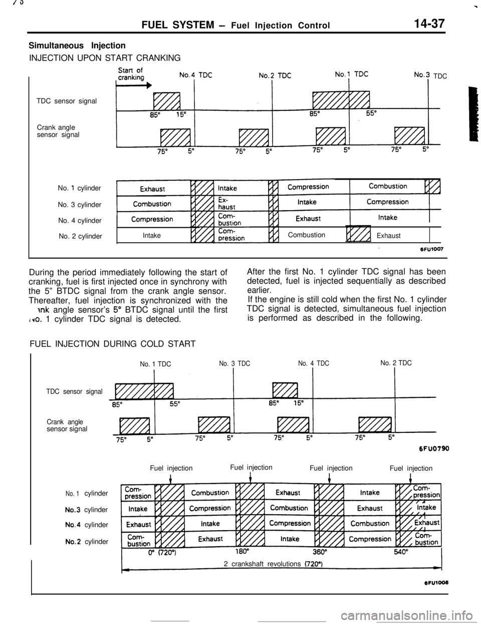
FUEL SYSTEM -Fuel Injection Control14-37Simultaneous Injection
INJECTION UPON START CRANKING
TDC sensor signal
Crank angle
sensor signal
No.
1 cylinder
No. 3 cylinder
No. 4 cylinder
No. 2 cylinder
TDC
IntakeCombustion
ExhaustDuring the period immediately following the start ofAfter the first No. 1 cylinder TDC signal has been
cranking, fuel is first injected once in synchrony withdetected, fuel is injected sequentially as described
the 5” BTDC signal from the crank angle sensor.
earlier.Thereafter, fuel injection is synchronized with theIf the engine is still cold when the first No. 1 cylinder
jnk angle sensor’s 5” BTDC signal until the firstTDC signal is detected, simultaneous fuel injection
i~o. 1 cylinder TDC signal is detected.is performed as described in the following.
FUEL INJECTION DURING COLD START
No. 1 TDCNo. 3 TDCNo. 4 TDCNo. 2 TDC
TDC sensor signal
Crank anglesensor signal
No. 1cylinderNo.3cylinderNo.4cylinderNo.2cylinder
6FUO790Fuel injection
1Fuel injection
Fuel injection1Fuel injection12 crankshaft revolutions
(720’)
Page 150 of 391
FUEL SYSTEM - Fuel Injection Control
When cranking the cold engine, fuel is injected into
all four cylinders simultaneously twice for every
crankshaft revolution, and fuel injection is synchro-
nized with the crank angle sensor’s 5” BTDC signal.
INCREASED FUEL INJECTION DURING ACCELERATION
No.1 TDC
TDC sensor signal
85”Crank angle
sensor signal
No.
1 cylinderINo. 3 cylinder
IIntakeNo.3 TDC
INo.4 TDCIIncreased fuel injection
during acceleratiqn
8
bxhaustNo. 4 cylinder
No. 2 cylinder
During acceleration, an increased amount of fuel
according to the degree of acceleration is injected
simultaneously into all four cylinders every 10
msecs., in addition to the sequential injection.
-
Page 151 of 391
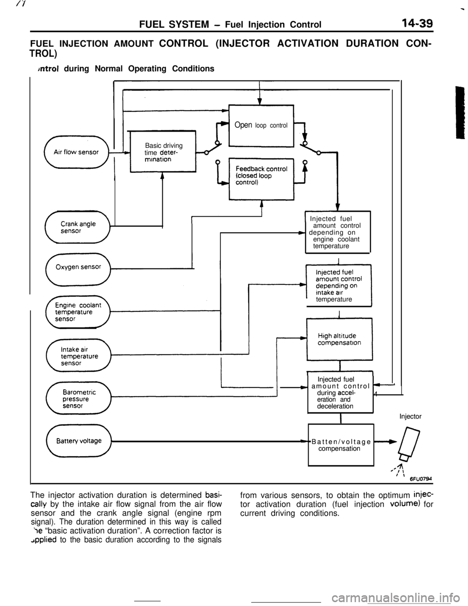
FUEL SYSTEM- Fuel Injection Control14-39FUEL INJECTION AMOUNT CONTROL (INJECTOR ACTIVATION DURATION CON-
TROL)
bntrol during Normal Operating Conditions
Open loop control
( ArrflowsensorBasic driving
time deter-
-”mination
i( Injected fuel
amount control
s depending on
engine coolant
temperature
I
II
””compensatron
Injected fuel Injected fuel
c amount control t-c amount control t-during accel-during accel-4 4eration and eration anddeceleration decelerationIIInjector Injector
+ Batten/voltage --W+ Batten/voltage --Wcompensation compensation
QQ44=I,=I,f \f \6FU07M6FU07Mtemperature
II
The injector activation duration is determined
basi-
tally by the intake air flow signal from the air flow
sensor and the crank angle signal (engine rpm
signal). The duration determined in this way is called‘le “basic activation duration”. A correction factor is
applied to the basic duration according to the signalsfrom various sensors, to obtain the optimum
injec-tor activation duration (fuel injection volume) for
current driving conditions.
Page 152 of 391
14-40FUEL SYSTEM - Fuel Injection Control
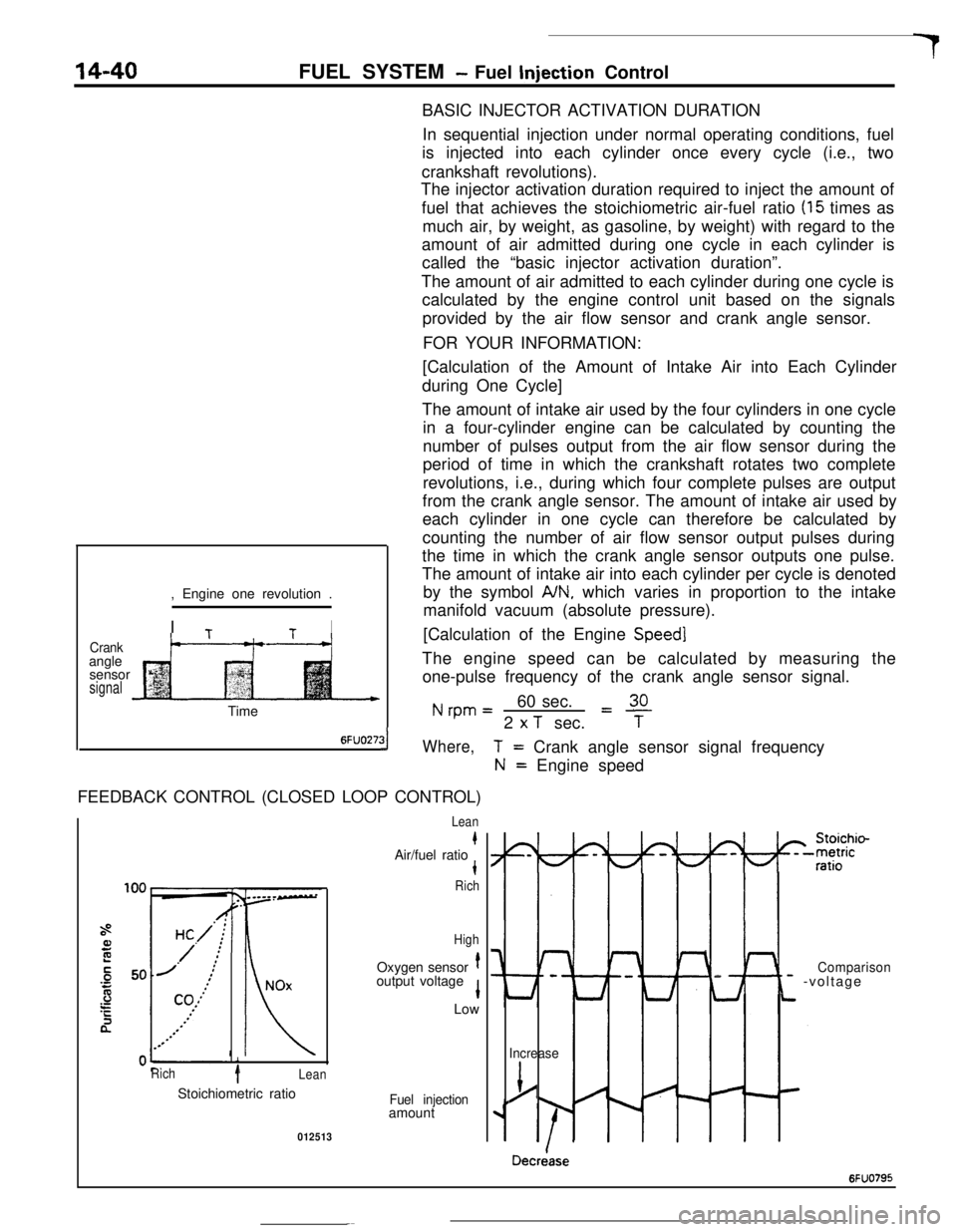
BASIC INJECTOR ACTIVATION DURATION
In sequential injection under normal operating conditions, fuel
is injected into each cylinder once every cycle (i.e., two
crankshaft revolutions).
The injector activation duration required to inject the amount of
fuel that achieves the stoichiometric air-fuel ratio
(15 times as
much air, by weight, as gasoline, by weight) with regard to the
amount of air admitted during one cycle in each cylinder is
called the “basic injector activation duration”.
The amount of air admitted to each cylinder during one cycle is
calculated by the engine control unit based on the signals
provided by the air flow sensor and crank angle sensor.
FOR YOUR INFORMATION:
Crankangle
sensor
signal, Engine one revolution .
I
TtI
t--“---t-+[Calculation of the Amount of Intake Air into Each Cylinder
during One Cycle]
The amount of intake air used by the four cylinders in one cycle
in a four-cylinder engine can be calculated by counting the
number of pulses output from the air flow sensor during the
period of time in which the crankshaft rotates two complete
revolutions, i.e., during which four complete pulses are output
from the crank angle sensor. The amount of intake air used by
each cylinder in one cycle can therefore be calculated by
counting the number of air flow sensor output pulses during
the time in which the crank angle sensor outputs one pulse.
The amount of intake air into each cylinder per cycle is denoted
by the symbol
A/N, which varies in proportion to the intake
manifold vacuum (absolute pressure).
[Calculation of the Engine
Speed]The engine speed can be calculated by measuring the
one-pulse frequency of the crank angle sensor signal.
Nrpm=60 sec.L!!L2
x T sec.TTime
6FUO27:31Where,FEEDBACK CONTROL (CLOSED LOOP CONTROL)
i
Rich1Lean
T= Crank angle sensor signal frequency
N= Engine speed
Lean
kAir/fuel ratiot
Rich
HighOxygen sensor
toutput voltage
1Low
Stoichiometric ratio
Fuel injectionamount
012513
I-
Lt
Comparison- -voltage
Increase
j/
Decriase
6FUO795