1990 MITSUBISHI ECLIPSE engine
[x] Cancel search: enginePage 118 of 391

14-6FUEL SYSTEM -Fuel Supply and Fuel Pressure Control
intake manifold/I\
Engine
Fuel
03AOOlOThe fuel supply system comprises electromagnetic
type injectors, a delivery pipe, a fuel pressure
regulator, a motor-driven fuel pump, and the engine
control unit, which activates and controls the injec-
tors and fuel pump based on data supplied by the
various sensors.
After being filtered by an in-tank filter, the fuel is
pumped from the tank and is filtered again by an
external filter before it is distributed to the injectors
through the delivery pipe. The pressure of fuel
delivered to the injectors is regulated by the fuel
pressure
reoulator; excess fuel after pressure reg-ulation has been performed is returned to the fuel
tankThe injectors are activated on command from the
engine control unit and inject the fuel to each intake
port of cylinder head sequentially according to the
predetermined ignition order.
In addition, a fuel-pressure control valve has been
equipped in order to maintain idling stability of turbo
models immediately after restarting under high- -
temperature conditions.
The fuel tank is located under the floor of the rear
seat, thus giving it protection in the event of a
rear-end collision. A fuel pump drive terminal is
provided in the engine compartment for greater
serviceability.
-
SPECIFICATIONSItems
Fuel pump
Type
Delivery rate
liters (gals.VHr
Delivery pressurekPa (psi)
Fuel pressure regulator
Tvw
Regulated fuel pressurekPa (psi)
Fuel filter
Rated flow rate
liters (qts.)/min.
Filter areacm’ (in.‘)
Injectors
TypeCoil resistance
n
--
.- -_-_
SpecificationsMotor-driven, in-tank type
Minimum 90 (23.8)
450 - 600 (64 - 85)
Diaphragm type
335 (47.6)
255 (36.3)
2
(2.1)
1,500 (233)Solenoid type
,.13-16
2-3
I
Page 119 of 391

FUEL SYSTEM -Fuel Supply and Fuel Pressure Control14-7FUEL TANK
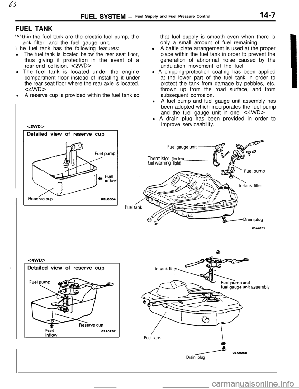
m/ithin the fuel tank are the electric fuel pump, the
.ank filter, and the fuel gauge unit.
-I he fuel tank has the following features:
lThe fuel tank is located below the rear seat floor,thus giving it protection in the event of a
rear-end collision.
<2WD>l The fuel tank is located under the engine
compartment floor instead of installing it under
the rear seat floor where the rear axle is located.
<4WD>lA reserve cup is provided within the fuel tank so
!Detailed view of reserve cup
t2WD>Detaiied view of reserve cup
t4WD>
Fuel03AO267
Fuelthat fuel supply is smooth even when there is
only a small amount of fuel remaining.
lA baffle plate arrangement is used at the proper
place within the fuel tank in order to prevent the
generation of abnormal noise caused by the
undulation movement of the fuel.
l A chipping-protection coating has been applied
at the lower part of the fuel tank in order to
protect the tank from damage by pebbles, etc.
thrown up from the road surface, and from
subsequent corrosion.
lA fuel pump and fuel gauge unit assembly has
been adopted which incorporates the fuel pump
and the fuel gauge unit in one.
<4WD>l A drain plug has been provided in order to
improve serviceability.
Thermistor (for low
fuel warning light)In-tank filter
Fuel tankI
e
/ 03AO268
Drain plug
assembly
Page 120 of 391

14-8
rFUEL SYSTEM
-Fuel Supply and Fuel Pressure Control
FUEL PUMP
This fuel pump is known as the in-tank type becauseit is located within the fuel tank itself, surrounded by
the fuel. For this reason, the pump operation noise
is well insulated, and it has excellent resistance to
vapor-locks.This type of pump is also called the “wet type”
because even its internal parts are in contact with
the fuel. With a construction that is the unification of
a ferrite-type DC motor and an impeller-type pump,
the pump itself is composed of the impeller, which
is driven by the motor, as well as the casing and the
cover. There are, in addition, a relief valve (a safety
valve for protection of the fuel-pressure circuit) and
a check valve (to maintain residual pressure).
The electric fuel pump has the following features:
l It has greater discharge pressure
mechanical-type fuel pump, as wellthan a
as lessdischarge pulsation.
lIt has a lower level of operation sound that the
electromagnetic type (Bendix type) of fuelpump.
PRESSURE-SUPPLY OF FUEL
When the impeller is caused to rotate by the motor,
a pressure differential develops at the upper. and
lower parts of the impeller, caused by the grooves in
the circumference of the impeller.
When this happens, a whirlpool effect is generated
within the fuel pump, causing the fuel pressure to
become higher, thereby causing the fuel to be
expelled from the pump chamber and to pass
through the motor, opening the check valve, and to
be discharged from the discharge port.
Discharge port
4Check!nRelief valve
DC mo
-lllll1 I/
Circum-ferential
flow pumr
II’ f-Pump
casing
J
Pumpcovert
lntakler 03R0071REWEF VALVE
If for some reason, such as an abnormal condition at the
_discharge side, the fuel were not to be discharged, the fuel
pressure within the fuel pump would become abnormally high.
Thus, when the pressure within the fuel pump reaches
450-600 kPa (64-85 psi), the relief valve opens and the
pressure escapes, so that, the fuel line pressure does not
increase to the regulated level or above.
CHECK VALVE
When the pump stops, the check valve is closed by spring
force, so that there is high pressure remaining within the fuel
line.By in this way maintaining a high pressure within the fuel line,
the restarting of the engine becomes easier, and vapor-locks at
high temperature are prevented.
-
-_..I
-~
Page 122 of 391

14-10
INJECTORFUEL SYSTEM
-Fuel Supply and Fuel Pressure Control
Intake port
lelivelYPipte
,FilterSpringAn injector is mounted on each of the four intake ports of the
cylinder head.
The injector is activated by electric current controlled by the
engine control unit.Wh-en current flows through the solenoid coil, the plunger and
needle valve, which form a single unit are magnetically
attracted, causing the injector nozzle to open and fuel to be
injected.When the current is interrupted, the plunger and needle valve
are pushed back by the spring, closing the injector nozzle.
Page 123 of 391

FUEL SYSTEM -Fuel Supply and Fuel Pressure Control
FUEL-PRESSURE CONTROL VALVE
14-11To fuel
-
Fuel-pressureregulatorFuel-pressurecontrol valve
Intake-airEnginecontrol
unit
Usually, the negative pressure (vacuum) of the
intake manifold is applied to the fuel-pressure
regulator, and, because the fuel pressure is thus
held at a fixed constant level relative to the pressure
within the intake manifold, the amount to fuel
injected is regulated so as to be proportional to the
injectors’ actuation time. If, however, the engine
coolant-temperature and the intake air temperature
are high when then engine is started, the engine
control unit sends a flow of current to the fuel-
pressure control valve, with the result that outside
air (atmospheric) pressure acts upon the fuel-
pressure regulator.
0Fuel ump
1chec terminal 1!Fuel pumpAs a result. the
fuel pressure is increased and the
generation of fuel vapors caused by high tem-
perature is suppressed, thereby maintaining idling
stability immediately after restarting under
high-temperature conditions.
Note that there is a return to the usual fuel pressure
level after two minutes or more have passed after
starting is completed.
In addition, the circuitry of the fuel-pressure control
valve. is interrupted, thus controlling so that the fuel
pressure corresponds to supercharging pressure,
under high-load driving conditions (during super-
charged driving by the turbocharger).
FU,EL PUMP CHECK TERMINAL
This terminal is for directly driving the fuel pump.
By applying the battery voltage directly to this terminal, you can
check fuel pump operation or check fuel leaks from the
fuel
line.
__. - ---
Page 124 of 391

140’I2FUEL SYSTEM- Intake Air Control
INTAKE AIR CONTROL
GENERAL DESCRIPTION
Rl4oA?, Speed adjusting screwIdle oositionswitch-
Throttle valve
0
+ Bypass air flow
before metenng
Q Bypass air fjow
Iafter metenng
Idle soeed control servo
-?hrottle position sensor
Fast idle air valve
oolant from thermostat case
ITo return pipe6FUO777Control of the volume of intake air is performed by the throttle
valve, the speed adjusting screw, the fast idle air valve and the
idle speed control servo, all of which are mounted on
ttithrottle body.
iControl by idle
w/d c;zk;;fast
hhidle air valve
Speed adjusting screwThrottle valve
m-30~22) of321 sofm 6of140~ 901164
Coolant temperature ‘C (OF)6Fuo!DURING ENGINE WARM UP
The intake air flow during fast idle is controlled by both the wax
actuated air valve which functions. in response to the engine
coolant temperature and the idle speed control servo that is
controlled by the engine control unit.
AFTER ENGINE HAS BEEN WARMED UP
Control of the intake air flow during curb idle (or the control of
curb idle speed) is performed by the idle speed control servo
which in turn is controlled by the engine control unit.
Refer to page 1445 for control of the idle speed control servo.The idle speed can be adjusted. by increasing or decreasing theintake air flow rate with the speed adjusting screw.
The off-idle intake air flow is controlled by the throttle
valve;operation of the accelerator pedal determines the degree that
the throttle valve is open at any particular moment.
-
.?‘h,
. .
Page 125 of 391

FUEL SYSTEM- Intake Air Control
SPECIFICATIONS
ternsThrottle body
Throttle bore diametermm
(in.1Fast idle air valve
TwValve closing temperature
“C (“F)
Idle speed control servo
TypeSpecifications
60 (2.362)
WAX type
Approximately 50
(122)Stepper motor type
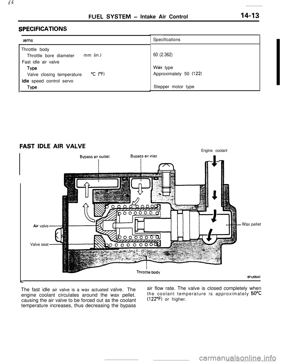
FAST IDLE AIR VALVEEngine coolant
LAir valve
Waxpellet
Valve seat
6FUO642The fast idle air valve is a wax actuated valve. The
engine coolant circulates around the wax pellet.
causing the air valve to be forced out as the coolant
temperature increases, thus decreasing the bypassair flow rate. The valve is closed completely when
the coolant temperature is approximately 50°C
(122°F) or higher.
Page 126 of 391

14-14
.._~- ---.FUEL SYSTEM
- Sensors
SENSORSRlUGENERAL DESCRIPTION
The types and functions of the sensors are as listedsend corresponding signals to the engine control
below. These sensors detect engine conditions and
unit.
SENSORSFUNCTION
AIR FLOW SENSOR
fSenses the intake arr volume with a Karman vortex flow meter.
INTAKE AIR TEMPERATURE
SENSORSenses the Intake air temperature (temperature of air at
the point of entry into the air cleaner).I
BAROMETRIC PRESSURE
SENSORISenses the barometric pressure faltrtude) wrth a
semiconductor diffusion type pressure sensor.
$;;OOf;T TEMPERATURESenses the engine coolant tern
THROTTLE
POSITISenses the throttle
tI
IDLE POSITION SWITCHSenses whether or not the accelerator pedal is being
operated with a contact switch.
Senses the top dead center on compression stroke of
NO. 1 and No. 4 cylinders with an LED and photo diode pair.
CRANK ANGLE SENSORSenses the crank angle of each cylinder with an LED
and photo diodepair.
T
OXYGEN SENSORSenses
actrvation of the air con
POWER STEERING OIL
PRESSURE SWITCHc-lSenses the power steering ‘load with a contact switch.
IGNITION SWITCHSenses ON/OFF
posrtion of the ignition switch.I
Senses engine cranking.
,
IGNITION TIMING
ADJUSTMENT TERMINALWhen this terminal is shorted, the ignition timing and idle
speed control servo is set in the adjustrng mode by the enginecontrol unit.
INHIBITOR SWITCHSenses the *P” and “N” positthe automatic transaxle.Senses.
by pieto-electric element,. cylinder block
vibrations that occur when there ISengineknocking.
CONTROL RELAY
(Fuel pump drive signal)
lFnorne ianitron sianal!Senses ignrtton coil prIman/ voltage.