Page 148 of 391

14-36FUEL SYSTEM- Fuel lniection Control
SFUOSlS
RESISTOR The resistor functions to regulate the current flowing in the
co,.of the injector.
Because the injector must respond instantly to fuel-injection
signals, the number of windings of the coil is reduced in order
to facilitate current rise when the current is flowing in the coil.
By doing so, the resistance of the injector coil becomes smaller
and a greater amount of current can flow, with the result that
the calorific value of the injector coil becomes greater, and
1overheating occurs.
For this reason, for turbocharger-equipped models (which have
low resistance of the injector coil), a resistor is provided
between the power supply (+) and the injector in order to
regulate the amount of current flowing in the coil.
FUEL INJECTION TIMING (INJECTOR AC-
TIVATION TIMING)
The fuel injection timing in multipoint fuel injection
has two modes, sequential and simultaneous. In
sequential injection, fuel is injected into each
cyl-inder sequentially throughout the entire normaloperating range including idling; in simultaneous
injection, fuel is injected simultaneously into all
cylinders during starting and acceleration.
Sequential Injection
r
No. 1cylinder
TDC sensor signal
Crank angle
sensor signal
No. 1 cylinder
No. 3 cylinder
No. 4 cylinder
No. 2 cylinder
In sequential injection, the’ injectors are activated foreach cylinder on the combustion stroke of the
piston. The No. 1 cylinder TDC signal is the
refer-
ence signal for sequential injection. The signal
represents the compression stroke in the No.
1cylinder and, with that timing as a reference, fuel isinjected into the cylinders in the order of
No.2,No.
1, No.3, and No.4. The injection for each
cylinder is synchronized with the crank angle
sen-sor’s 5” BTDC signal. Fuel is injected in each
cylinder once for every two revolutions of the
crankshaft.
-
Page 337 of 391

23-20BODY - Central Door LocksCENTRAL DOOR LOCKS
Ri... 4sThe central door-lock system, by which all doors can
be locked or unlocked (from the inside by using the
inside door lock knob at either front door, or from
the outside by using the door key), not only sewes
to reduce the trouble of individually locking orunlocking each door when passengers get out or
get in, but also maintains passenger safety.
For the central door-lock system, the operation of
the lock actuator is regulated by the door control
unit.
Door lock actuator(right side)Door-control unit
(left side)
Door lockcontrol relay16A0464
PTC heater
/MotorISwitchDOOR LOCK ACTUATOR
The actuator is light in weight and is the highly reliable motor
We.
NOTE
The door lock actuator incorporates an internal PTC thermist’-so as to Prevent damage as the result of overheating of
L
motor.*: PTC
is an acronym for Positive Temperature Coefficient.
The thermistor with a positive temperature coefficient
ofresistance provides more resistance as it generates
heat,thus limiting current and controlling the amount of
haat
generated.
Page 370 of 391

HEATERS AND AIR CONDITIONING - Heater Construction24-7
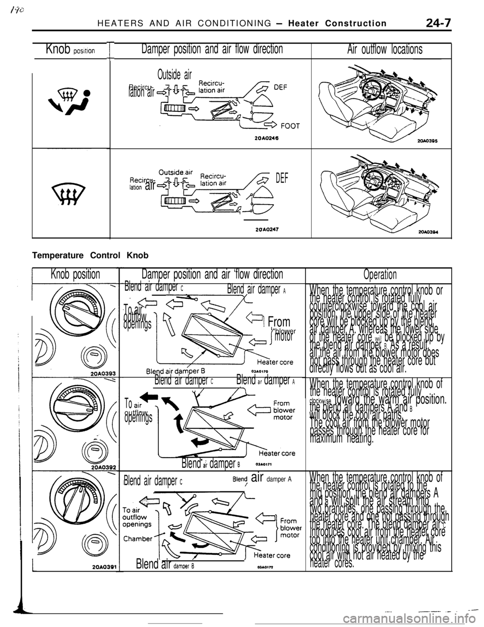
IKnob posltionDamper position and air flow direction
Air outflow locations
Outside air
Recircu-lation air
2010246
Recircu-iation airDEF
2OAO247Temperature Control Knob
IKnob positionDamper position and air ‘flow directionOperation
When the temperature control knob or
the heater control is rotated fully
counterclockwise toward the cool air
position, the upper side of the heater
core will be blocked up by the blend
air damper A. whereas the lower side
of the heater core
will be blocked up by
the blend air damper 8. As a result.
all the air from the blower motor does
not pass through the heater core but
directly flows out as cool air.
Blend air damper CBlend air damper A
x!= cY?l-nY-/
-1 From
To air Voutflowopenings*blower
motor
Hester ‘OreOUO,,O
Blend air damper CBlend air damper A,//7When the temperature control knob of
the heater control is rotated fully
ctockwise toward the warm air position.the blend air dampers A and Bwill block the cool air paths.
The cool air from the blower motor
passes through the heater core for
maximum heating..
Tooutflow
openings
Blend al’r damper B
When the temperature control knob of
the heater control is rotated to the
mid position, the blend air dampers A
and B will split the air stream intotwo branches, one passing through the
heater core and one not passing through
the heater core. The blend damper air
Cintroduces cool air from the heater core
top into the heater unit chamber. Air
conditioning is provided by mixing this
cool air with hot air heated by the
heater cores.
Blend air damper CBlend/ air damper AL
2OAO391Blend air damoer B
--.-__.__ ,_ .