1989 MITSUBISHI GALANT set
[x] Cancel search: setPage 3 of 1273

00-l
GENERAL
CONTENTS
GENERAL DATA AND SPECIFICATIONS.....23
HOWTOUSETHISMANUAL......................
3
Definition of Terms ......................................3
ExplanationofCircuitDiagrams..................7
Explanation of
ManualContents .................4
Explanation of the Troubleshooting
Guide .............................................................
6
Model
Indications .........................................3
Scope of Maintenance, Repair and
Servicing Explanations
..................................
3
Troubleshooting .............................................3
LUBRICATIONANDMAINTENANCE............
34
MAINTENANCE SERVICE............................... 39
AirCleanerElement
.....................................39
Automatic
Transaxle
.....................................43
Ball Joint and Steering Linkage Seals ........45
Brake Hoses................................................. 45
Disc Brake Pads ........................................... 44
Drive Belt (For Water Pump and
Generator) .......................................................
41
Drive
Shaft Boots .........................................45
Engine Coolant
............................................. 44
Engine Oil .....................................................
41
Engine Oil Filter ...........................................41
Exhaust System
............................................ 45
FuelHoses
...................................................39
Fuel System
.................................................39
Manual Transaxle ..........................................42
RearAxle......................................................45
Rear Drum Brake Linings and
RearWheel Cylinders
..................................44
Spark
Plugs...................................................40
Timing Belt...................................................40
MASTER
TROUBLESHOOTING.....................28
PRECAUTIONS
BEFORESERVICE................15
RECOMMENDED LUBRICANTS AND
LUBRICANT CAPACITIESTABLE..................35
SCHEDULED
MAINTENANCETABLE ...........38
SPECIAL HANDLING INSTRUCTIONS
FOR AWD MODELS
.......................................20
TABLE OF MAIN SEALANTS
AND
ADHESIVES ............................................46
TIGHTENING TORQUE
................................... 27
TOWING
ANDHOISTING ..............................17
VEHICLE
IDENTIFICATION .............................8
Chassis Number ...........................................
11
EngineModel
Stamping
...............................12
Theft Protection ............................................12
Vehicle Identification Code Chart Plate.......
8
Vehicle Identification Number List
..............8
Vehicle Identification Number Location .......
8
Vehicle Information
CodePlate...................1 1
Vehicle SafetyCertificationLabel................12
Page 7 of 1273
GENERAL - How to Use This Manual
QfitIIICQ CTEEQINC CFAR RnY..^-TV..&” Y.LLI.II.Y Y_.. w-1.
REMOVAL AND INSTALLATION
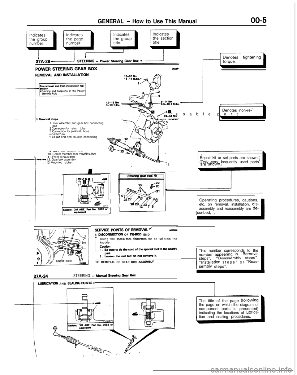
1, Jpn assemble and gear box connecting
2 Connectlo” for return tube
3 Connectm
for pressure hose4 cotter P!”6 T!e-rod end and knuckle connecting
I
J rl”.#l ~“,. dLlrr_. ..__
10. Center member rear mouniing
bou11, Front exhaust p’pe4. H 12. Gear box assembly
. . 13. Mounting rubber Denotes non-re-
p usable part
.
Y.T-*c As..
-
6
Repair kit or set parts are shown.
(Only very frequently used parts
Operating procedures, cautions,
II-’ iY,W11 ’etc. on removal, installation, dis-
se&an: 3rM&rr&paNo.~3W[scribed, ,~ 1assembly and reassembly are
de-
37A-24STEERING- NINA Steering Gear Box
-SERVICE POINTS OF
REMOVALJll37?kM6. DlSCONNECllON OF TIEROD END
Using the special tool, disconnect
the tie rod from theknuckle.ceurion1. BesretotiethewrdofthespeciaitodtomenP-.2. Loosenthenutbutdonotremoveit.
12. REMOVAL OF GEAR BOX ASSEMBLY
Thus number corresponds to the
number ?pyi:,“~&‘R~;;?Isteps”,“Installation steps” or “Reas-semblv steps”.
/LUBRlCATlON AND SEALING POINTS-
The title of the page (fOilOWingthe page on which the diagram of
component parts is presented)
indicating the locations of lubnca-
tion and sealingprocedures.
Page 22 of 1273
00-20GENERAL - Special Handling Instructions for AWD Models
SPECIAL HANDLING INSTRUCTIONS
FOR AWD MODELS
TOWIN
G
MomMA
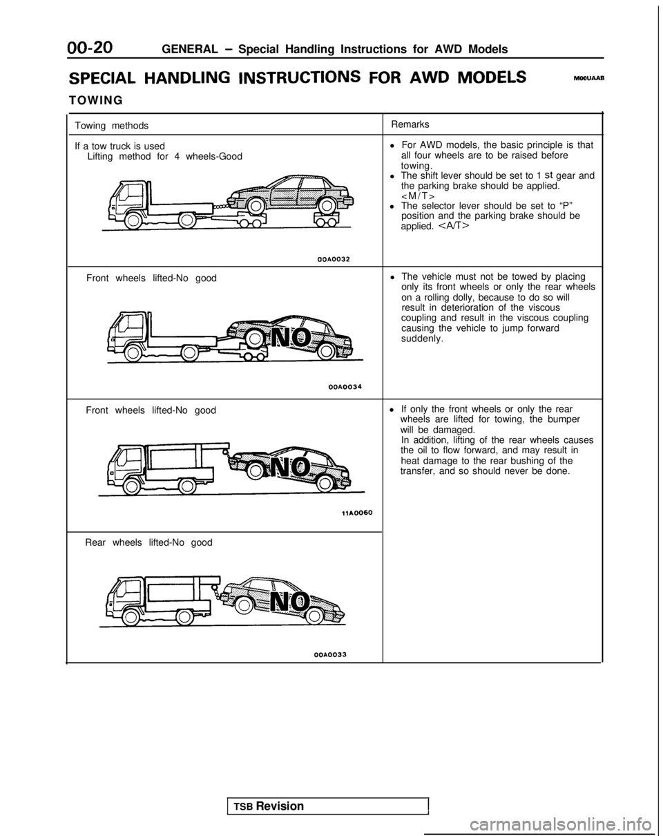
Towing methods
If a tow truck is used Lifting method for 4 wheels-Good Remarks
l For AWD models, the basic principle is that
all four wheels are to be raised before
towing.
l The shift lever should be set to 1
st gear and
the parking brake should be applied.
l The selector lever should be set to “P” position and the parking brake should be
applied.
OOA0032
Front wheels lifted-No good l The vehicle must not be towed by placing
only its front wheels or only the rear wheels
on a rolling dolly, because to do so willresult in deterioration of the viscous
coupling and result in the viscous coupling
causing the vehicle to jump forward
suddenly.
OOA0034
Front wheels lifted-No good l
If only the front wheels or only the rear
wheels are lifted for towing, the bumper
will be damaged. In addition, lifting of the rear wheels causes
the oil to flow forward, and may result in
heat damage to the rear bushing of the
transfer, and so should never be done.
Rear wheels lifted-No good
OOA0033
TSB Revision1
Page 23 of 1273
GENERAL - Special Handling Instructions for AWD Models00-21
Free roller
OOPO038
Axle stand
OOPOO37
Towino hook
Tenslon
bar
Front
eJ
Anchor plate
&-16PO209 14AO198
OOP003E
SPEEDOMETER TEST
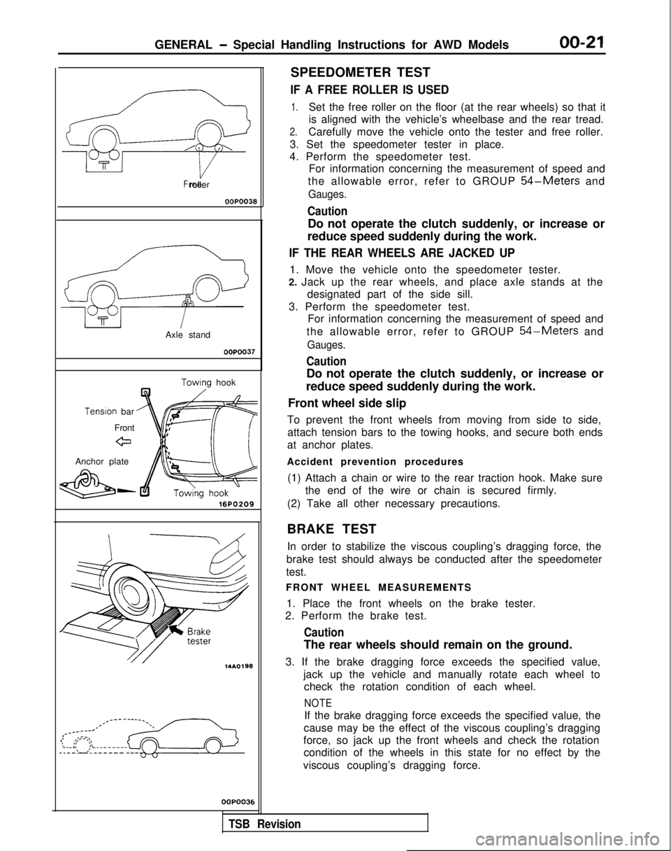
IF A FREE ROLLER IS USED
1.Set the free roller on the floor (at the rear wheels) so that it
is aligned with the vehicle’s wheelbase and the rear tread.
2.Carefully move the vehicle onto the tester and free roller.
3. Set the speedometer tester in place.
4. Perform the speedometer test. For information concerning the measurement of speed and
the allowable error, refer to GROUP
54-Meters and
Gauges.
Caution
Do not operate the clutch suddenly, or increase or
reduce speed suddenly during the work.
IF THE REAR WHEELS ARE JACKED UP
1. Move the vehicle onto the speedometer tester.
2. Jack up the rear wheels, and place axle stands at the designated part of the side sill.
3. Perform the speedometer test. For information concerning the measurement of speed and
the allowable error, refer to GROUP
54-Meters and
Gauges.
Caution
Do not operate the clutch suddenly, or increase or
reduce speed suddenly during the work.
Front wheel side slip
To prevent the front wheels from moving from side to side, attach tension bars to the towing hooks, and secure both ends
at anchor plates.
Accident prevention procedures (1) Attach a chain or wire to the rear traction hook. Make sure the end of the wire or chain is secured firmly.
(2) Take all other necessary precautions.
BRAKE TEST In order to stabilize the viscous coupling’s dragging force, the
brake test should always be conducted after the speedometer
test.
FRONT WHEEL MEASUREMENTS
1. Place the front wheels on the brake tester.
2. Perform the brake test.
Caution
The rear wheels should remain on the ground.
3. If the brake dragging force exceeds the specified value, jack up the vehicle and manually rotate each wheel tocheck the rotation condition of each wheel.
NOTE
If the brake dragging force exceeds the specified value, the
cause may be the effect of the viscous coupling’s dragging
force, so jack up the front wheels and check the rotation condition of the wheels in this state for no effect by the
viscous coupling’s dragging force.
,
TSB Revision
Page 24 of 1273
00-22GENERAL - Special Handling Instructions for AWD Models
REAR WHEEL MEASUREMENTS
After placing the rear wheels on the brake tester, follow thesame procedures as for the front wheel measurements.
WHEEL BALANCE
FRONT WHEEL MEASUREMENTS
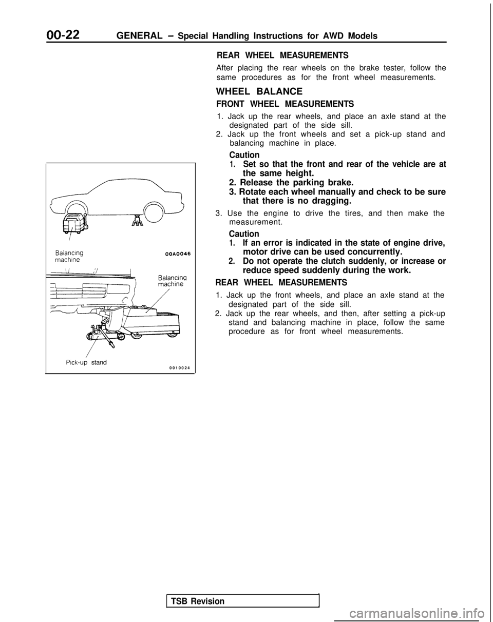
1. Jack up the rear wheels, and place an axle stand at the designated part of the side sill.
2. Jack up the front wheels and set a pick-up stand and balancing machine in place.
Caution
1.Set so that the front and rear of the vehicle are at
the same height. Balancing
machlne
OOA0046
Balancw
Pick-up stand
0010024
TSB Revision
2. Release the parking brake.
3. Rotate each wheel manually and check to be sure
that there is no dragging.
3. Use the engine to drive the tires, and then make the measurement.
Caution
1.If an error is indicated in the state of engine drive,
motor drive can be used concurrently.
2.Do not operate the clutch suddenly, or increase or
reduce speed suddenly during the work.
REAR WHEEL MEASUREMENTS
1. Jack up the front wheels, and place an axle stand at the
designated part of the side sill.
2. Jack up the rear wheels, and then, after setting a pick-up stand and balancing machine in place, follow the same
procedure as for front wheel measurements.
Page 31 of 1273
GENERAL - Master Troubleshooting00-29
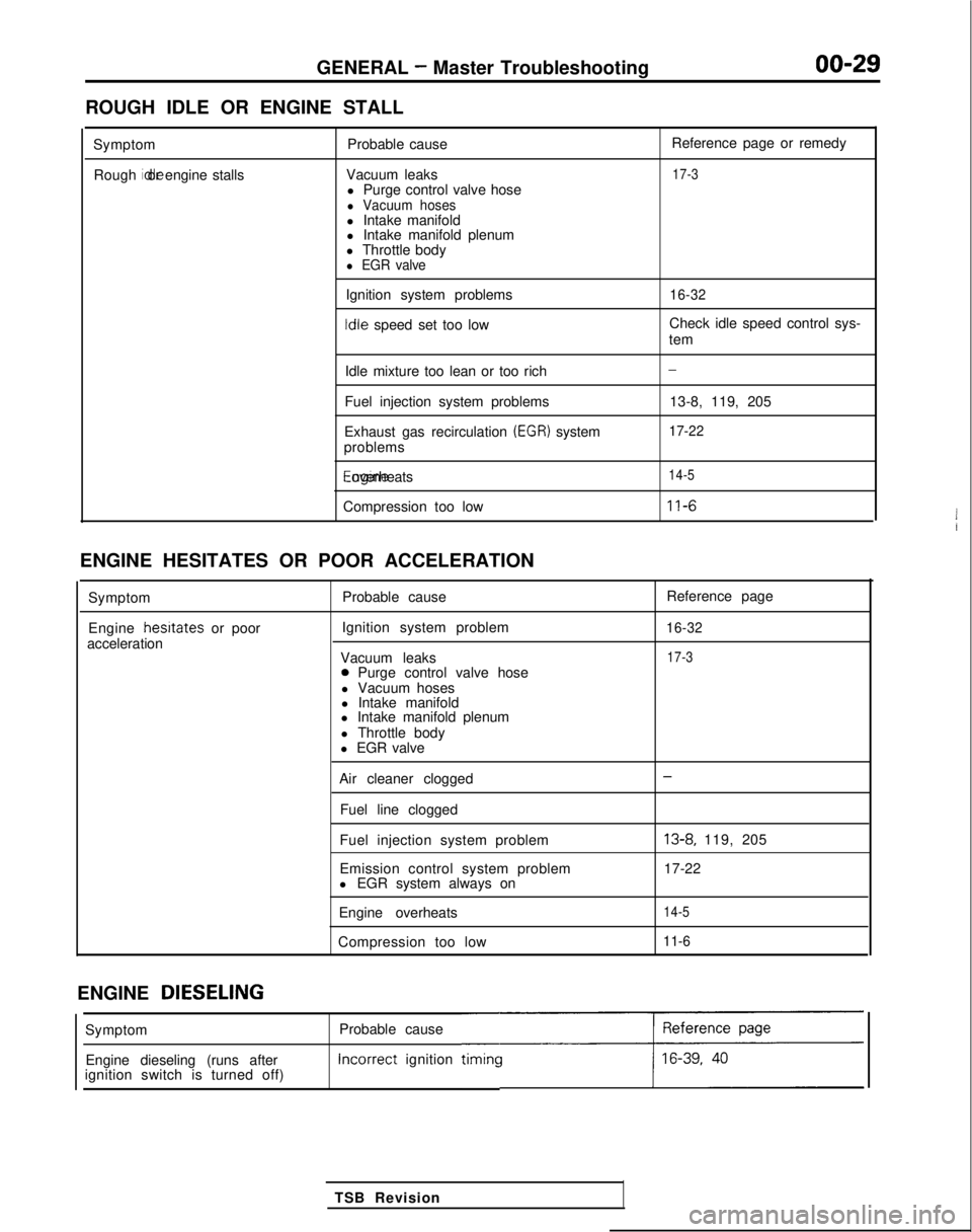
ROUGH IDLE OR ENGINE STALL
SymptomRough idle or engine stalls
Probable cause
Vacuum leaks l Purge control valve hose
l Vacuum hosesl Intake manifold
l Intake manifold plenum
l Throttle body
l EGR valve
Ignition system problems Idle
speed set too low Reference page or remedy
17-3
16-32
Check idle speed control sys-
tem
Idle mixture too lean or too rich
Fuel injection system problems
Exhaust gas recirculation
(EGR) system
problems Engine overheats
Compression too low
-
13-8, 119, 205
17-22
14-5
11-6
ENGINE HESITATES OR POOR ACCELERATION
Symptom
Engine hesrtates
or poor
acceleration Probable cause
Ignition system problem
Vacuum leaks
0 Purge control valve hose
l Vacuum hoses
l Intake manifold
l Intake manifold plenum
l Throttle body
l EGR valve Reference page
16-32
17-3
Air cleaner clogged
Fuel line clogged
Fuel injection system problem
Emission control system problem
l EGR system always on
Engine overheats
Compression too low-
13-8, 119, 205
17-22
14-5
11-6
ENGINE DIESELING
Probable cause Incorrect
ignition
timincc
TSB Revision
Symptom
Engine dieseling (runs after
ignition switch is turned off)
Page 42 of 1273
00-40GENERAL- Maintenance Service
Caution
The air cleaner cover should be removed carefully,
because it includes the volume air flow sensor.
/
(5) Remove the air cleaner element.(6) Set a new air cleaner element and install the air cleaner cover.
I hose,I
Plug gapgauge
Measurementrection01
If
0110182
(1) Disconnect the volume air flow sensor connector.
(2) Disconnect the breather hose, purge hose, by-pass air hose and boost hose connections.
(3)Remove the air intake hose on the air cleaner cover side
and then move the air intake hose to the front of the air
cleaner body.
(4) Unclamp the air cleaner cover.
Caution
Care must be taken when removing the air cleaner
cover, because the volume air flow sensor is at-
tached.
(5) Take out the air cleaner element.
(6) Check the air cleaner element for dirt or clogging; if necessary, clean by using compressed air.
(7) Replace the air cleaner element if the dirt or clogging
is
serious.
(8) Insert the element into the air cleaner body and install the air cleaner cover.
(9) Install the air intake hose.
(10)Connect the breather hose, purge hose, by-pass air
hose and boost hose.
(11
)Connect the volume air flow sensor connector.
4. SPARK PLUGS (Replace)
h%OSAOFa
1. Spark plugs must spark properly to assure proper engine performance and reduce exhaust emission
level.
Therefore, they should be replaced periodically with
new ones.
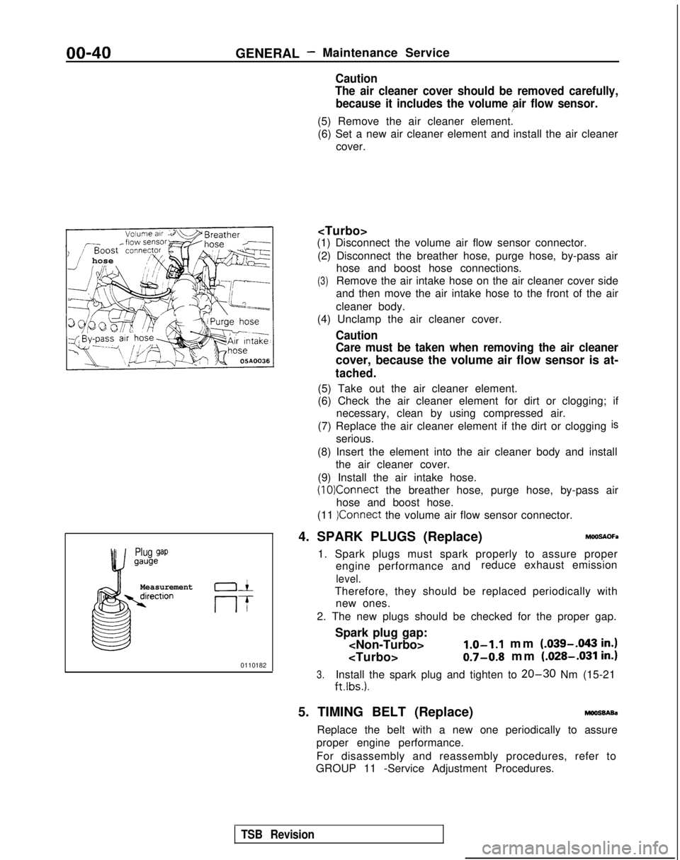
2. The new plugs should be checked for the proper gap.
Spark plug gap:
mm (.039-.043
in.)
0.7-0.8 mm (.028-.031 in.)
3.Install the spark plug and tighten to 20-30 Nm (15-21
ftlbs.).
5. TIMING BELT (Replace)moossAsa
Replace the belt with a new one periodically to assure
proper engine performance.
For disassembly and reassembly procedures, refer to
GROUP 11 -Service Adjustment Procedures.
TSB Revision
Page 46 of 1273
GENERAL -Maintenance Service
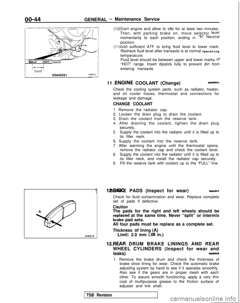
(1O)Star-t engine and allow to idle for at least two minutes.
Then, with parking brake on, move selector
fever
momentarily to each position, ending in “N” Neutral
position.
(11)Add sufficient ATF to bring fluid level to lower mark.
Recheck fluid level after transaxle is at normal Operating
temperature. Fluid level should be between upper and lower marks of
“HOT” range, Insert dipstick fully to prevent dirt from
entering transaxle.
OOA0051
11 .ENGINE
COOLANT (Change)MOOSEEAC
Check the cooling system parts, such as radiator, heater,
and oil cooler hoses, thermostat and connections for
leakage and damage.
CHANGE COOLANT
1. Remove the radiator cap.
2. Loosen the drain plug to drain the coolant.
3. Drain the coolant from the reserve tank.
4. After draining the coolant, tighten the drain plug securely.
5.Supply the coolant into the radiator until it is filled up to
its filler neck.
6. Supply the coolant into the reserve tank.
7. After warming the engine until the thermostat opens, remove the radiator cap and check the coolant level.
8.Supply the coolant into the radiator until it is filled up to
its filler neck, and install the radiator cap securely.
9.Fill the reserve tank with coolant up to the “FULL” line.
14K512
1 12.DISC BRAKE PADS (Inspect for wear) MWSBFA
Check for fluid contamination and wear. Replace complete
set of pads if defective.
Caution
The pads for the right and left wheels should be
reDlaced at the same time. Never “split” or intermix
brkke pad sets.
All four pads must be replace as a complete set.
Thickness of lining (A)
Limit: 2.0 mm (.08 in.)
13.REAR DRUM BRAKE LININGS AND REAR
WHEEL CYLINDERS (Inspect for wear and
leaks)MOOSBGB
1. Remove the brake drum and check the thickness of brake shoe lining for wear. Check the automatic brake
adjusting system by hand to see if it operates smoothly.
Also see if the gears are in proper mesh with each
other. To assure smooth functioning, apply a very thin
coat of multipurpose grease to the friction surface of
adjuster and link shaft.
TSB Revision1