1989 FORD FIESTA wheel torque
[x] Cancel search: wheel torquePage 243 of 296

8Refitting is a reversal of the removal
procedure.
Front direction indicator side
repeater
9 Remove the appropriate front wheel arch
liner as described in Chapter 11.
10 Remove the appropriate sill scuff plate as
described in Chapter 11, and release the clip
securing the insulation to the panel forward of
the lower A-pillar.
11 Disconnect the supply lead connector and
the earth lead, then release their grommet
from its panel location.
12 From outside the vehicle, twist the light
assembly to release it, then withdraw it and its
leads.
13 Refitting is a reversal of the removal
procedure, ensuring that the grommet is
seated correctly in its panel location.
Rear light cluster
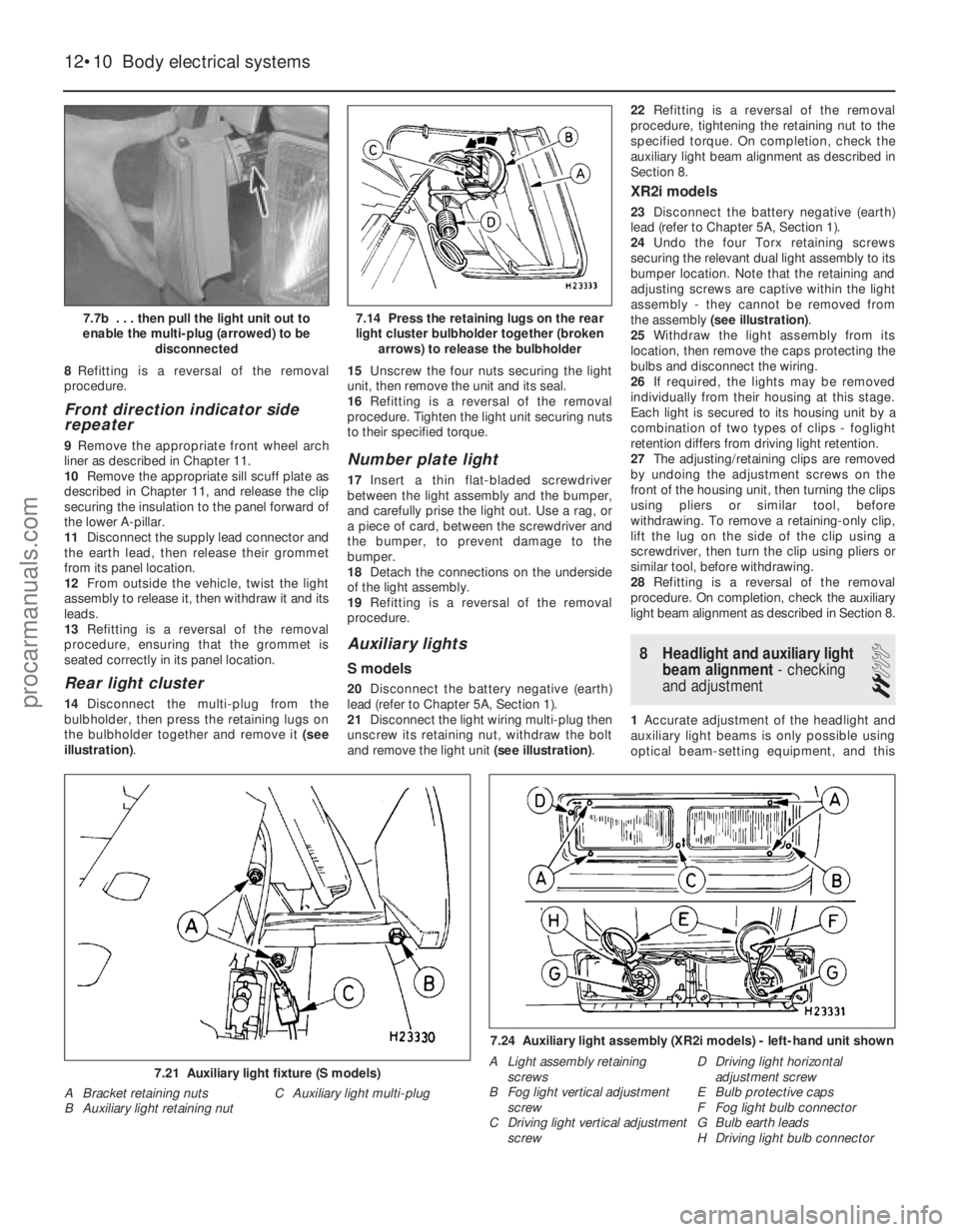
14 Disconnect the multi-plug from the
bulbholder, then press the retaining lugs on
the bulbholder together and remove it (see
illustration) . 15
Unscrew the four nuts securing the light
unit, then remove the unit and its seal.
16 Refitting is a reversal of the removal
procedure. Tighten the light unit securing nuts
to their specified torque.
Number plate light
17 Insert a thin flat-bladed screwdriver
between the light assembly and the bumper,
and carefully prise the light out. Use a rag, or
a piece of card, between the screwdriver and
the bumper, to prevent damage to the
bumper.
18 Detach the connections on the underside
of the light assembly.
19 Refitting is a reversal of the removal
procedure.
Auxiliary lights
S models
20 Disconnect the battery negative (earth)
lead (refer to Chapter 5A, Section 1).
21 Disconnect the light wiring multi-plug then
unscrew its retaining nut, withdraw the bolt
and remove the light unit (see illustration).22
Refitting is a reversal of the removal
procedure, tightening the retaining nut to the
specified torque. On completion, check the
auxiliary light beam alignment as described in
Section 8.
XR2i models
23 Disconnect the battery negative (earth)
lead (refer to Chapter 5A, Section 1).
24 Undo the four Torx retaining screws
securing the relevant dual light assembly to its
bumper location. Note that the retaining and
adjusting screws are captive within the light
assembly - they cannot be removed from
the assembly (see illustration) .
25 Withdraw the light assembly from its
location, then remove the caps protecting the
bulbs and disconnect the wiring.
26 If required, the lights may be removed
individually from their housing at this stage.
Each light is secured to its housing unit by a
combination of two types of clips - foglight
retention differs from driving light retention.
27 The adjusting/retaining clips are removed
by undoing the adjustment screws on the
front of the housing unit, then turning the clips
using pliers or similar tool, before
withdrawing. To remove a retaining-only clip,
lift the lug on the side of the clip using a
screwdriver, then turn the clip using pliers or
similar tool, before withdrawing.
28 Refitting is a reversal of the removal
procedure. On completion, check the auxiliary
light beam alignment as described in Section 8.
8 Headlight and auxiliary light
beam alignment - checking
and adjustment
2
1 Accurate adjustment of the headlight and
auxiliary light beams is only possible using
optical beam-setting equipment, and this
12•10 Body electrical systems
7.24 Auxiliary light assembly (XR2i models) - left-hand unit shown
A Light assembly retaining screws
B Fog light vertical adjustment screw
C Driving light vertical adjustment screw D Driving light horizontal
adjustment screw
E Bulb protective caps
F Fog light bulb connector
G Bulb earth leads
H Driving light bulb connector
7.21 Auxiliary light fixture (S models)
A Bracket retaining nuts C Auxiliary light multi-plug
B Auxiliary light retaining nut
7.14 Press the retaining lugs on the rear
light cluster bulbholder together (broken arrows) to release the bulbholder7.7b . . . then pull the light unit out to
enable the multi-plug (arrowed) to be disconnected
1595Ford Fiesta Remakeprocarmanuals.com
http://vnx.su
Page 247 of 296

2Carry out the procedure detailed in Sec-
tion 16, paragraphs 2 to 6.
3 Remove the collars from the pivot shafts,
unscrew the pivot shaft securing nuts and
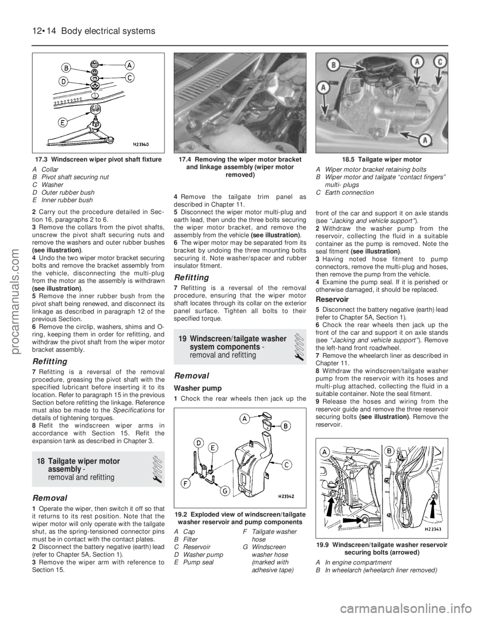
remove the washers and outer rubber bushes
(see illustration) .
4 Undo the two wiper motor bracket securing
bolts and remove the bracket assembly from
the vehicle, disconnecting the multi-plug
from the motor as the assembly is withdrawn
(see illustration) .
5 Remove the inner rubber bush from the
pivot shaft being renewed, and disconnect its
linkage as described in paragraph 12 of the
previous Section.
6 Remove the circlip, washers, shims and O-
ring, keeping them in order for refitting, and
withdraw the pivot shaft from the wiper motor
bracket assembly.
Refitting
7 Refitting is a reversal of the removal
procedure, greasing the pivot shaft with the
specified lubricant before inserting it to its
location. Refer to paragraph 15 in the previous
Section before refitting the linkage. Reference
must also be made to the Specificationsfor
details of tightening torques.
8 Refit the windscreen wiper arms in
accordance with Section 15. Refit the
expansion tank as described in Chapter 3.
18 Tailgate wiper motor assembly -
removal and refitting
1
Removal
1 Operate the wiper, then switch it off so that
it returns to its rest position. Note that the
wiper motor will only operate with the tailgate
shut, as the spring-tensioned connector pins
must be in contact with the contact plates.
2 Disconnect the battery negative (earth) lead
(refer to Chapter 5A, Section 1).
3 Remove the wiper arm with reference to
Section 15. 4
Remove the tailgate trim panel as
described in Chapter 11.
5 Disconnect the wiper motor multi-plug and
earth lead, then undo the three bolts securing
the wiper motor bracket, and remove the
assembly from the vehicle (see illustration).
6 The wiper motor may be separated from its
bracket by undoing the three mounting bolts
securing it. Note washer/spacer and rubber
insulator fitment.
Refitting
7 Refitting is a reversal of the removal
procedure, ensuring that the wiper motor
shaft locates through its collar on the exterior
panel surface. Tighten all bolts to their
specified torque.
19 Windscreen/tailgate washer system components -
removal and refitting
1
Removal
Washer pump
1 Chock the rear wheels then jack up the front of the car and support it on axle stands
(see
“Jacking and vehicle support” ).
2 Withdraw the washer pump from the
reservoir, collecting the fluid in a suitable
container as the pump is removed. Note the
seal fitment (see illustration) .
3 Having noted hose fitment to pump
connectors, remove the multi-plug and hoses,
then remove the pump from the vehicle.
4 Examine the pump seal. If it is perished or
otherwise damaged, it should be replaced.
Reservoir
5 Disconnect the battery negative (earth) lead
(refer to Chapter 5A, Section 1).
6 Chock the rear wheels then jack up the
front of the car and support it on axle stands
(see “Jacking and vehicle support” ). Remove
the left-hand front roadwheel.
7 Remove the wheelarch liner as described in
Chapter 11.
8 Withdraw the windscreen/tailgate washer
pump from the reservoir with its hoses and
multi-plug attached, collecting the fluid in a
suitable container. Note the seal fitment.
9 Release the hoses and wiring from the
reservoir guide and remove the three reservoir
securing bolts (see illustration) . Remove the
reservoir.
12•14 Body electrical systems
19.9 Windscreen/tailgate washer reservoir
securing bolts (arrowed)
A In engine compartment
B In wheelarch (wheelarch liner removed)
19.2 Exploded view of windscreen/tailgate washer reservoir and pump components
A Cap
B Filter
C Reservoir
D Washer pump
E Pump seal F Tailgate washer
hose
G Windscreen
washer hose
(marked with
adhesive tape)
18.5 Tailgate wiper motor
A Wiper motor bracket retaining bolts
B Wiper motor and tailgate “contact fingers” multi- plugs
C Earth connection17.4 Removing the wiper motor bracket and linkage assembly (wiper motor removed)17.3 Windscreen wiper pivot shaft fixture
A Collar
B Pivot shaft securing nut
C Washer
D Outer rubber bush
E Inner rubber bush
1595Ford Fiesta Remakeprocarmanuals.com
http://vnx.su