1989 FORD FIESTA stop start
[x] Cancel search: stop startPage 280 of 296
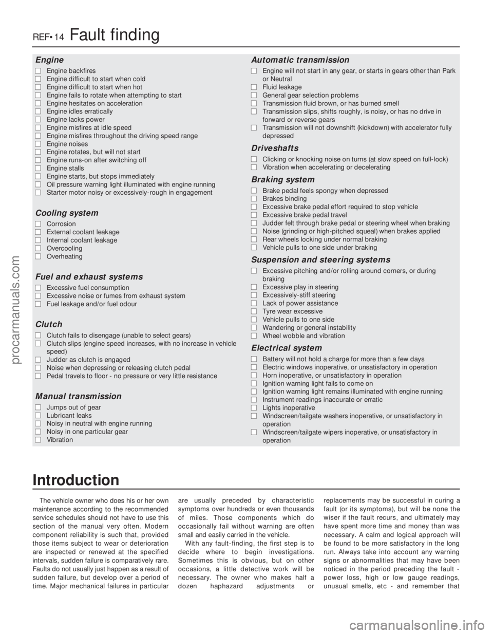
The vehicle owner who does his or her own
maintenance according to the recommended
service schedules should not have to use this
section of the manual very often. Modern
component reliability is such that, provided
those items subject to wear or deterioration
are inspected or renewed at the specified
intervals, sudden failure is comparatively rare.
Faults do not usually just happen as a result of
sudden failure, but develop over a period of
time. Major mechanical failures in particular are usually preceded by characteristic
symptoms over hundreds or even thousands
of miles. Those components which do
occasionally fail without warning are often
small and easily carried in the vehicle.
With any fault-finding, the first step is to
decide where to begin investigations.
Sometimes this is obvious, but on other
occasions, a little detective work will be
necessary. The owner who makes half a
dozen haphazard adjustments or replacements may be successful in curing a
fault (or its symptoms), but will be none the
wiser if the fault recurs, and ultimately may
have spent more time and money than was
necessary. A calm and logical approach will
be found to be more satisfactory in the long
run. Always take into account any warning
signs or abnormalities that may have been
noticed in the period preceding the fault -
power loss, high or low gauge readings,
unusual smells, etc - and remember that
Engine
m
m
Engine backfires
m
m Engine difficult to start when cold
m
m Engine difficult to start when hot
m
m Engine fails to rotate when attempting to start
m
m Engine hesitates on acceleration
m
m Engine idles erratically
m
m Engine lacks power
m
m Engine misfires at idle speed
m
m Engine misfires throughout the driving speed range
m
m Engine noises
m
m Engine rotates, but will not start
m
m Engine runs-on after switching off
m
m Engine stalls
m
m Engine starts, but stops immediately
m
m Oil pressure warning light illuminated with engine running
m
m Starter motor noisy or excessively-rough in engagement
Cooling system
m
mCorrosion
m
m External coolant leakage
m
m Internal coolant leakage
m
m Overcooling
m
m Overheating
Fuel and exhaust systems
m
mExcessive fuel consumption
m
m Excessive noise or fumes from exhaust system
m
m Fuel leakage and/or fuel odour
Clutch
m
mClutch fails to disengage (unable to select gears)
m
m Clutch slips (engine speed increases, with no increase in vehicle
speed)
m m Judder as clutch is engaged
m
m Noise when depressing or releasing clutch pedal
m
m Pedal travels to floor - no pressure or very little resistance
Manual transmission
m
mJumps out of gear
m
m Lubricant leaks
m
m Noisy in neutral with engine running
m
m Noisy in one particular gear
m
m Vibration
Automatic transmission
m
mEngine will not start in any gear, or starts in gears other than Park
or Neutral
m m Fluid leakage
m
m General gear selection problems
m
m Transmission fluid brown, or has burned smell
m
m Transmission slips, shifts roughly, is noisy, or has no drive in
forward or reverse gears
m m Transmission will not downshift (kickdown) with accelerator fully
depressed
Driveshafts
m mClicking or knocking noise on turns (at slow speed on full-lock)
m
m Vibration when accelerating or decelerating
Braking system
m
mBrake pedal feels spongy when depressed
m
m Brakes binding
m
m Excessive brake pedal effort required to stop vehicle
m
m Excessive brake pedal travel
m
m Judder felt through brake pedal or steering wheel when braking
m
m Noise (grinding or high-pitched squeal) when brakes applied
m
m Rear wheels locking under normal braking
m
m Vehicle pulls to one side under braking
Suspension and steering systems
m
mExcessive pitching and/or rolling around corners, or during
braking
m m Excessive play in steering
m
m Excessively-stiff steering
m
m Lack of power assistance
m
m Tyre wear excessive
m
m Vehicle pulls to one side
m
m Wandering or general instability
m
m Wheel wobble and vibration
Electrical system
m
mBattery will not hold a charge for more than a few days
m
m Electric windows inoperative, or unsatisfactory in operation
m
m Horn inoperative, or unsatisfactory in operation
m
m Ignition warning light fails to come on
m
m Ignition warning light remains illuminated with engine running
m
m Instrument readings inaccurate or erratic
m
m Lights inoperative
m
m Windscreen/tailgate washers inoperative, or unsatisfactory in
operation
m m Windscreen/tailgate wipers inoperative, or unsatisfactory in
operation
REF•14Fault finding
1595 Ford Fiesta Remake
Introduction
procarmanuals.com
http://vnx.su
Page 281 of 296
1595 Ford Fiesta Remake
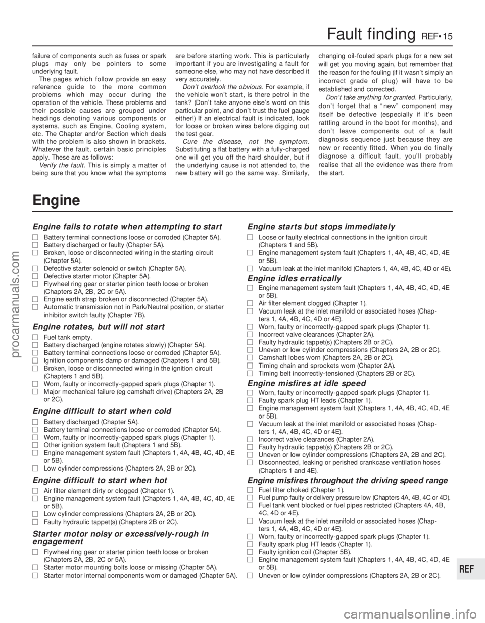
failure of components such as fuses or spark
plugs may only be pointers to some
underlying fault.
The pages which follow provide an easy
reference guide to the more common
problems which may occur during the
operation of the vehicle. These problems and
their possible causes are grouped under
headings denoting various components or
systems, such as Engine, Cooling system,
etc. The Chapter and/or Section which deals
with the problem is also shown in brackets.
Whatever the fault, certain basic principles
apply. These are as follows:
Verify the fault . This is simply a matter of
being sure that you know what the symptoms are before starting work. This is particularly
important if you are investigating a fault for
someone else, who may not have described it
very accurately.
Don’t overlook the obvious . For example, if
the vehicle won’t start, is there petrol in the
tank? (Don’t take anyone else’s word on this
particular point, and don’t trust the fuel gauge
either!) If an electrical fault is indicated, look
for loose or broken wires before digging out
the test gear. Cure the disease, not the symptom .
Substituting a flat battery with a fully-charged
one will get you off the hard shoulder, but if
the underlying cause is not attended to, the
new battery will go the same way. Similarly, changing oil-fouled spark plugs for a new set
will get you moving again, but remember that
the reason for the fouling (if it wasn’t simply an
incorrect grade of plug) will have to be
established and corrected.
Don’t take anything for granted . Particularly,
don’t forget that a “new” component may
itself be defective (especially if it’s been
rattling around in the boot for months), and
don’t leave components out of a fault
diagnosis sequence just because they are
new or recently fitted. When you do finally
diagnose a difficult fault, you’ll probably
realise that all the evidence was there from
the start.
Fault findingREF•15
REF
Engine
Engine fails to rotate when attempting to start
m
m Battery terminal connections loose or corroded (Chapter 5A).
m
m Battery discharged or faulty (Chapter 5A).
m
m Broken, loose or disconnected wiring in the starting circuit
(Chapter 5A).
m m Defective starter solenoid or switch (Chapter 5A).
m
m Defective starter motor (Chapter 5A).
m
m Flywheel ring gear or starter pinion teeth loose or broken
(Chapters 2A, 2B, 2C or 5A).
m m Engine earth strap broken or disconnected (Chapter 5A).
m
m Automatic transmission not in Park/Neutral position, or starter
inhibitor switch faulty (Chapter 7B).
Engine rotates, but will not start
m mFuel tank empty.
m
m Battery discharged (engine rotates slowly) (Chapter 5A).
m
m Battery terminal connections loose or corroded (Chapter 5A).
m
m Ignition components damp or damaged (Chapters 1 and 5B).
m
m Broken, loose or disconnected wiring in the ignition circuit
(Chapters 1 and 5B).
m m Worn, faulty or incorrectly-gapped spark plugs (Chapter 1).
m
m Major mechanical failure (eg camshaft drive) (Chapters 2A, 2B
or 2C).
Engine difficult to start when cold
m mBattery discharged (Chapter 5A).
m
m Battery terminal connections loose or corroded (Chapter 5A).
m
m Worn, faulty or incorrectly-gapped spark plugs (Chapter 1).
m
m Other ignition system fault (Chapters 1 and 5B).
m
m Engine management system fault (Chapters 1, 4A, 4B, 4C, 4D, 4E
or 5B).
m m Low cylinder compressions (Chapters 2A, 2B or 2C).
Engine difficult to start when hot
m
mAir filter element dirty or clogged (Chapter 1).
m
m Engine management system fault (Chapters 1, 4A, 4B, 4C, 4D, 4E
or 5B).
m m Low cylinder compressions (Chapters 2A, 2B or 2C).
m
m Faulty hydraulic tappet(s) (Chapters 2B or 2C).
Starter motor noisy or excessively-rough in
engagement
m mFlywheel ring gear or starter pinion teeth loose or broken
(Chapters 2A, 2B, 2C or 5A).
m m Starter motor mounting bolts loose or missing (Chapter 5A).
m
m Starter motor internal components worn or damaged (Chapter 5A).
Engine starts but stops immediately
m
mLoose or faulty electrical connections in the ignition circuit
(Chapters 1 and 5B).
m m Engine management system fault (Chapters 1, 4A, 4B, 4C, 4D, 4E
or 5B).
m m Vacuum leak at the inlet manifold (Chapters 1, 4A, 4B, 4C, 4D or 4E).
Engine idles erratically
m
mEngine management system fault (Chapters 1, 4A, 4B, 4C, 4D, 4E
or 5B).
m m Air filter element clogged (Chapter 1).
m
m Vacuum leak at the inlet manifold or associated hoses (Chap-
ters 1, 4A, 4B, 4C, 4D or 4E).
m m Worn, faulty or incorrectly-gapped spark plugs (Chapter 1).
m
m Incorrect valve clearances (Chapter 2A).
m
m Faulty hydraulic tappet(s) (Chapters 2B or 2C).
m
m Uneven or low cylinder compressions (Chapters 2A, 2B or 2C).
m
m Camshaft lobes worn (Chapters 2A, 2B or 2C).
m
m Timing chain and sprockets worn (Chapter 2A).
m
m Timing belt incorrectly-tensioned (Chapters 2B or 2C).
Engine misfires at idle speed
m
mWorn, faulty or incorrectly-gapped spark plugs (Chapter 1).
m
m Faulty spark plug HT leads (Chapter 1).
m
m Engine management system fault (Chapters 1, 4A, 4B, 4C, 4D, 4E
or 5B).
m m Vacuum leak at the inlet manifold or associated hoses (Chap-
ters 1, 4A, 4B, 4C, 4D or 4E).
m m Incorrect valve clearances (Chapter 2A).
m
m Faulty hydraulic tappet(s) (Chapters 2B or 2C).
m
m Uneven or low cylinder compressions (Chapters 2A, 2B and 2C).
m
m Disconnected, leaking or perished crankcase ventilation hoses
(Chapters 1 and 4E).
Engine misfires throughout the driving speed range
m mFuel filter choked (Chapter 1).
m
m Fuel pump faulty or delivery pressure low (Chapters 4A, 4B, 4C or 4D).\
m
m Fuel tank vent blocked or fuel pipes restricted (Chapters 4A, 4B,
4C, 4D or 4E).
m m Vacuum leak at the inlet manifold or associated hoses (Chap-
ters 1, 4A, 4B, 4C, 4D or 4E).
m m Worn, faulty or incorrectly-gapped spark plugs (Chapter 1).
m
m Faulty spark plug HT leads (Chapter 1).
m
m Faulty ignition coil (Chapter 5B).
m
m Engine management system fault (Chapters 1, 4A, 4B, 4C, 4D, 4E
or 5B).
m m Uneven or low cylinder compressions (Chapters 2A, 2B or 2C).
procarmanuals.com
http://vnx.su
Page 284 of 296
1595 Ford Fiesta Remake
REF•18Fault finding
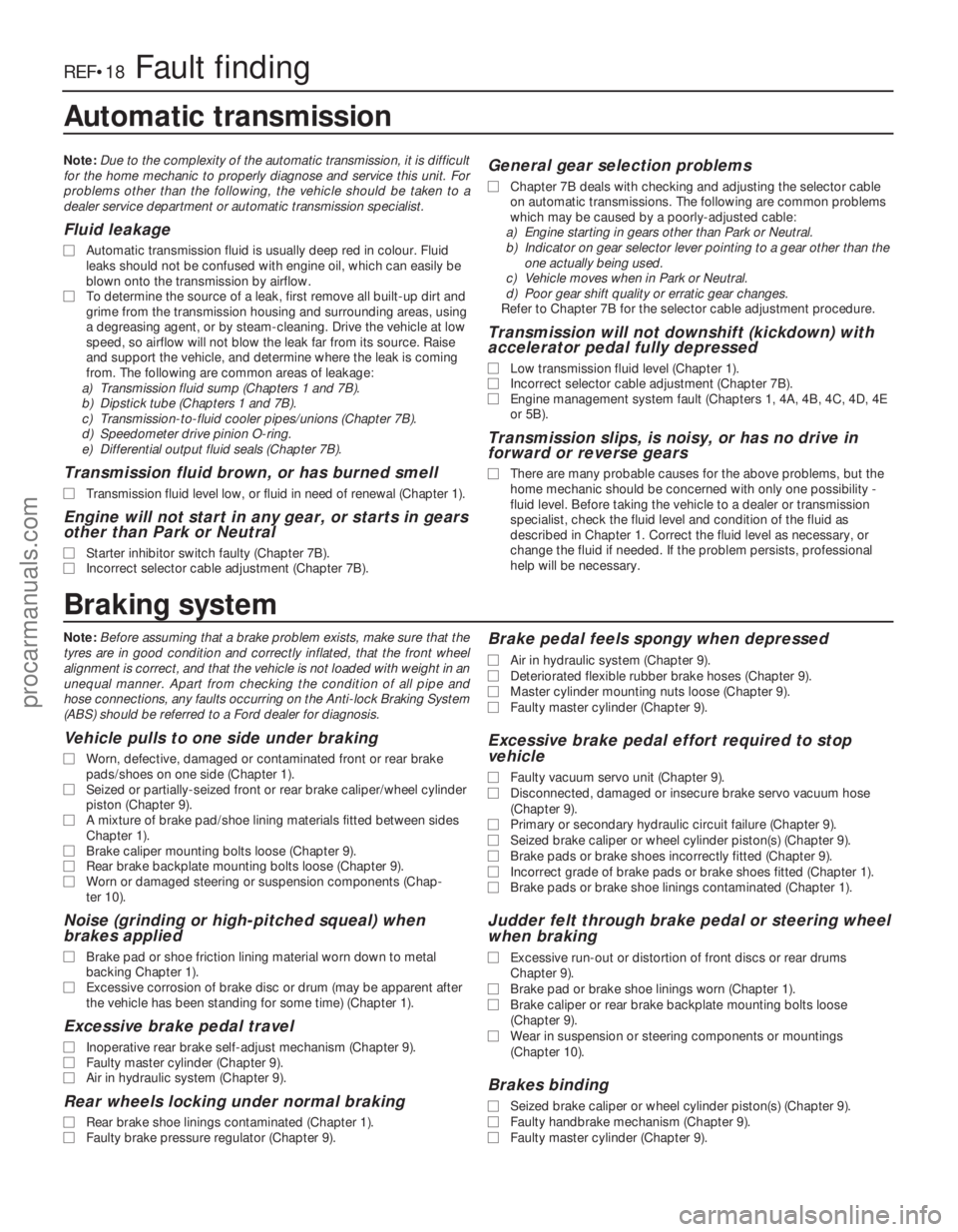
Braking system
Note:Before assuming that a brake problem exists, make sure that the
tyres are in good condition and correctly inflated, that the front wheel\
alignment is correct, and that the vehicle is not loaded with weight in \
an
unequal manner. Apart from checking the condition of all pipe and
hose connections, any faults occurring on the Anti-lock Braking System
(ABS) should be referred to a Ford dealer for diagnosis.
Vehicle pulls to one side under braking
m m Worn, defective, damaged or contaminated front or rear brake
pads/shoes on one side (Chapter 1).
m m Seized or partially-seized front or rear brake caliper/wheel cylinder
piston (Chapter 9).
m m A mixture of brake pad/shoe lining materials fitted between sides
Chapter 1).
m m Brake caliper mounting bolts loose (Chapter 9).
m
m Rear brake backplate mounting bolts loose (Chapter 9).
m
m Worn or damaged steering or suspension components (Chap-
ter 10).
Noise (grinding or high-pitched squeal) when
brakes applied
m mBrake pad or shoe friction lining material worn down to metal
backing Chapter 1).
m m Excessive corrosion of brake disc or drum (may be apparent after
the vehicle has been standing for some time) (Chapter 1).
Excessive brake pedal travel
m mInoperative rear brake self-adjust mechanism (Chapter 9).
m
m Faulty master cylinder (Chapter 9).
m
m Air in hydraulic system (Chapter 9).
Rear wheels locking under normal braking
m
mRear brake shoe linings contaminated (Chapter 1).
m
m Faulty brake pressure regulator (Chapter 9).
Brake pedal feels spongy when depressed
m
mAir in hydraulic system (Chapter 9).
m
m Deteriorated flexible rubber brake hoses (Chapter 9).
m
m Master cylinder mounting nuts loose (Chapter 9).
m
m Faulty master cylinder (Chapter 9).
Excessive brake pedal effort required to stop
vehicle
m mFaulty vacuum servo unit (Chapter 9).
m
m Disconnected, damaged or insecure brake servo vacuum hose
(Chapter 9).
m m Primary or secondary hydraulic circuit failure (Chapter 9).
m
m Seized brake caliper or wheel cylinder piston(s) (Chapter 9).
m
m Brake pads or brake shoes incorrectly fitted (Chapter 9).
m
m Incorrect grade of brake pads or brake shoes fitted (Chapter 1).
m
m Brake pads or brake shoe linings contaminated (Chapter 1).
Judder felt through brake pedal or steering wheel
when braking
m mExcessive run-out or distortion of front discs or rear drums
Chapter 9).
m m Brake pad or brake shoe linings worn (Chapter 1).
m
m Brake caliper or rear brake backplate mounting bolts loose
(Chapter 9).
m m Wear in suspension or steering components or mountings
(Chapter 10).
Brakes binding
m mSeized brake caliper or wheel cylinder piston(s) (Chapter 9).
m
m Faulty handbrake mechanism (Chapter 9).
m
m Faulty master cylinder (Chapter 9).
Automatic transmission
Note: Due to the complexity of the automatic transmission, it is difficult
for the home mechanic to properly diagnose and service this unit. For
problems other than the following, the vehicle should be taken to a
dealer service department or automatic transmission specialist.
Fluid leakage
m m Automatic transmission fluid is usually deep red in colour. Fluid
leaks should not be confused with engine oil, which can easily be
blown onto the transmission by airflow.
m m To determine the source of a leak, first remove all built-up dirt and
grime from the transmission housing and surrounding areas, using
a degreasing agent, or by steam-cleaning. Drive the vehicle at low
speed, so airflow will not blow the leak far from its source. Raise
and support the vehicle, and determine where the leak is coming
from. The following are common areas of leakage:
a) Transmission fluid sump (Chapters 1 and 7B).
b) Dipstick tube (Chapters 1 and 7B).
c) Transmission-to-fluid cooler pipes/unions (Chapter 7B).
d) Speedometer drive pinion O-ring.
e) Differential output fluid seals (Chapter 7B).
Transmission fluid brown, or has burned smell
m m Transmission fluid level low, or fluid in need of renewal (Chapter 1).\
Engine will not start in any gear, or starts in gears
other than Park or Neutral
m mStarter inhibitor switch faulty (Chapter 7B).
m
m Incorrect selector cable adjustment (Chapter 7B).
General gear selection problems
m
mChapter 7B deals with checking and adjusting the selector cable
on automatic transmissions. The following are common problems
which may be caused by a poorly-adjusted cable:
a) Engine starting in gears other than Park or Neutral.
b) Indicator on gear selector lever pointing to a gear other than the
one actually being used.
c) Vehicle moves when in Park or Neutral.
d) Poor gear shift quality or erratic gear changes.
Refer to Chapter 7B for the selector cable adjustment procedure.
Transmission will not downshift (kickdown) with
accelerator pedal fully depressed
m m Low transmission fluid level (Chapter 1).
m
m Incorrect selector cable adjustment (Chapter 7B).
m
m Engine management system fault (Chapters 1, 4A, 4B, 4C, 4D, 4E
or 5B).
Transmission slips, is noisy, or has no drive in
forward or reverse gears
m mThere are many probable causes for the above problems, but the
home mechanic should be concerned with only one possibility -
fluid level. Before taking the vehicle to a dealer or transmission
specialist, check the fluid level and condition of the fluid as
described in Chapter 1. Correct the fluid level as necessary, or
change the fluid if needed. If the problem persists, professional
help will be necessary.
procarmanuals.com
http://vnx.su
Page 291 of 296
1595 Ford Fiesta Remake
Glossary of technical termsREF•25
REF
JJump startStarting the engine of a vehicle
with a discharged or weak battery by
attaching jump leads from the weak battery to
a charged or helper battery.
LLoad Sensing Proportioning Valve (LSPV) A
brake hydraulic system control valve that
works like a proportioning valve, but also
takes into consideration the amount of weight
carried by the rear axle.
Locknut A nut used to lock an adjustment
nut, or other threaded component, in place.
For example, a locknut is employed to keep
the adjusting nut on the rocker arm in
position.
Lockwasher A form of washer designed to
pr event an attaching nut from working loose.
MMacPherson strut A type of front
suspension system devised by Earle
MacPherson at Ford of England. In its original
form, a simple lateral link with the anti-roll bar
cr eates the lower control arm. A long strut - an
integral coil spring and shock absorber - is
mounted between the body and the steering
knuckle. Many modern so-called MacPherson
strut systems use a conventional lower A-arm
and don’t rely on the anti-roll bar for location. Multimeter An electrical test instrument with
the capability to measure voltage, current and
resistance.
NNOx Oxides of Nitrogen. A common toxic
pollutant emitted by petrol and diesel engines
at higher temperatures.
OOhm The unit of electrical resistance. One
volt applied to a resistance of one ohm will
pr oduce a current of one amp.
Ohmmeter An instrument for measuring
electrical resistance.
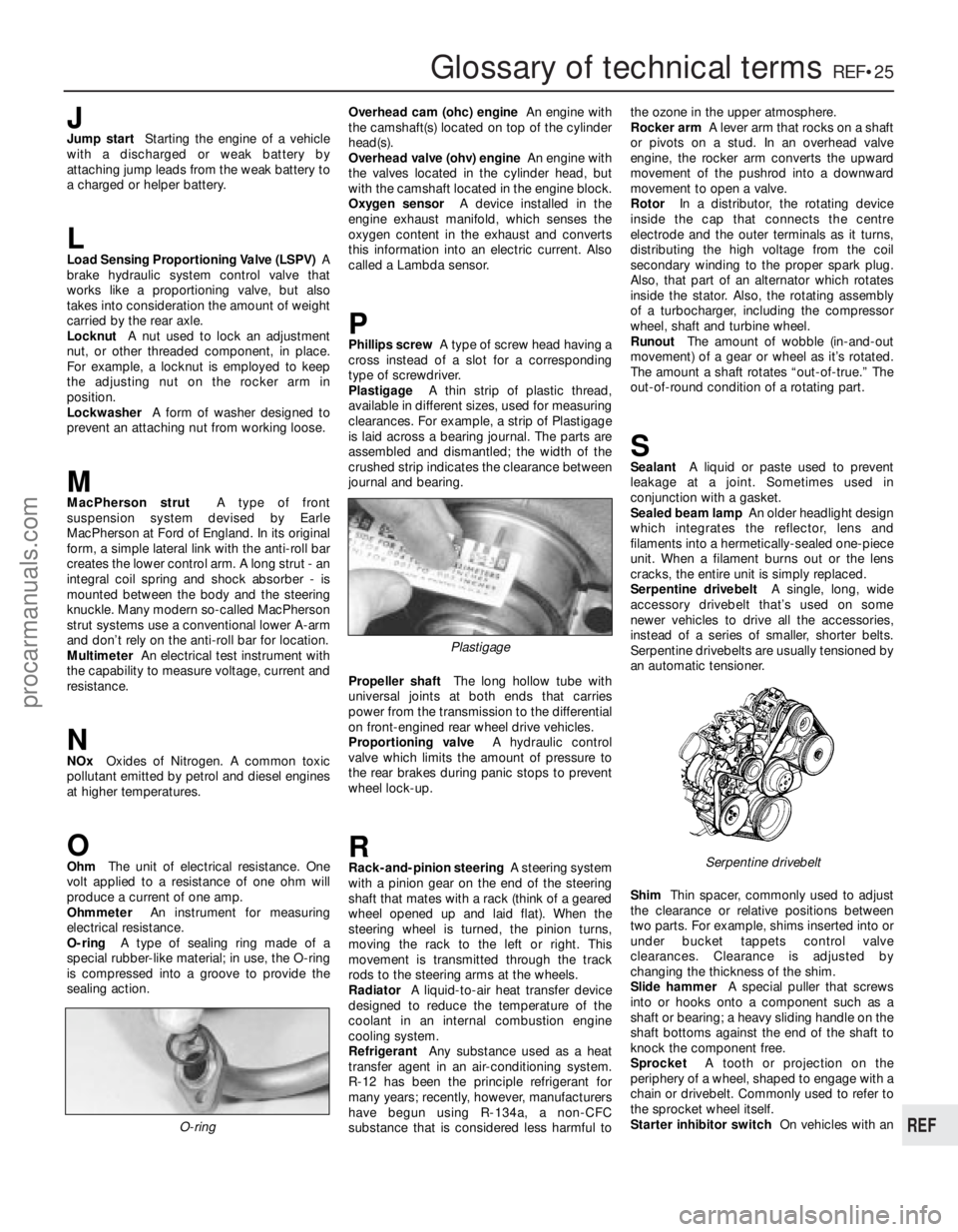
O-ring A type of sealing ring made of a
special rubber-like material; in use, the O-ring
is compressed into a groove to provide the
sealing action. Overhead cam (ohc) engine
An engine with
the camshaft(s) located on top of the cylinder
head(s).
Overhead valve (ohv) engine An engine with
the valves located in the cylinder head, but
with the camshaft located in the engine block.
Oxygen sensor A device installed in the
engine exhaust manifold, which senses the
oxygen content in the exhaust and converts
this information into an electric current. Also
called a Lambda sensor.
PPhillips screw A type of screw head having a
cr oss instead of a slot for a corresponding
type of screwdriver.
Plastigage A thin strip of plastic thread,
available in different sizes, used for measuring clearances. For example, a strip of Plastigage
is laid across a bearing journal. The parts areassembled and dismantled; the width of the
crushed strip indicates the clearance between
jour nal and bearing.
Pr opeller shaft The long hollow tube with
universal joints at both ends that carries
power from the transmission to the differential on front-engined rear wheel drive vehicles.
Pr oportioning valve A hydraulic control
valve which limits the amount of pressure to
the rear brakes during panic stops to prevent
wheel lock-up.
RRack-and-pinion steering A steering system
with a pinion gear on the end of the steering
shaft that mates with a rack (think of a geared
wheel opened up and laid flat). When the
steering wheel is turned, the pinion turns,
moving the rack to the left or right. This
movement is transmitted through the track
r ods to the steering arms at the wheels.
Radiator A liquid-to-air heat transfer device
designed to reduce the temperature of the
coolant in an internal combustion engine
cooling system.
Refrigerant Any substance used as a heat
transfer agent in an air-conditioning system.
R-12 has been the principle refrigerant for
many years; recently, however, manufacturers
have begun using R-134a, a non-CFC
substance that is considered less harmful to the ozone in the upper atmosphere.
Rocker arm
A lever arm that rocks on a shaft
or pivots on a stud. In an overhead valve
engine, the rocker arm converts the upward
movement of the pushrod into a downward
movement to open a valve.
Rotor In a distributor, the rotating device
inside the cap that connects the centre
electr ode and the outer terminals as it turns,
distributing the high voltage from the coil
secondary winding to the proper spark plug.
Also, that part of an alternator which rotates
inside the stator. Also, the rotating assembly
of a turbocharger, including the compressor
wheel, shaft and turbine wheel.
Runout The amount of wobble (in-and-out
movement) of a gear or wheel as it’ s rotated.
The amount a shaft rotates “out-of-true.” The
out-of-r ound condition of a rotating part.
SSealant A liquid or paste used to prevent
leakage at a joint. Sometimes used in
conjunction with a gasket.
Sealed beam lamp An older headlight design
which integrates the reflector, lens and
filaments into a hermetically-sealed one-piece
unit. When a filament burns out or the lens
cracks, the entire unit is simply replaced.
Serpentine drivebelt A single, long, wide
accessory drivebelt that’s used on some
newer vehicles to drive all the accessories,
instead of a series of smaller, shorter belts.
Serpentine drivebelts are usually tensioned by
an automatic tensioner.
Shim Thin spacer, commonly used to adjust
the clearance or relative positions between
two parts. For example, shims inserted into or
under bucket tappets control valve
clearances. Clearance is adjusted by
changing the thickness of the shim.
Slide hammer A special puller that screws
into or hooks onto a component such as a
shaft or bearing; a heavy sliding handle on the
shaft bottoms against the end of the shaft to
knock the component free.
Sprocket A tooth or projection on the
periphery of a wheel, shaped to engage with a
chain or drivebelt. Commonly used to refer to
the sprocket wheel itself.
Starter inhibitor switch On vehicles with an
O-ring
Serpentine drivebelt
Plastigage
procarmanuals.com
http://vnx.su
Page 292 of 296

1595 Ford Fiesta Remake
REF•26Glossary of technical terms
automatic transmission, a switch that
prevents starting if the vehicle is not in Neutral
or Park.
Strut See MacPherson strut.
TTappet A cylindrical component which
transmits motion from the cam to the valve
stem, either directly or via a pushrod and
r ocker arm. Also called a cam follower.
Thermostat A heat-controlled valve that
r egulates the flow of coolant between the
cylinder block and the radiator, so maintaining
optimum engine operating temperature. A
thermostat is also used in some air cleaners in
which the temperature is regulated.
Thrust bearing The bearing in the clutch
assembly that is moved in to the release levers
by clutch pedal action to disengage the
clutch. Also referred to as a release bearing.
Timing belt A toothed belt which drives the
camshaft. Serious engine damage may result
if it breaks in service.
Timing chain A chain which drives the
camshaft.
Toe-in The amount the front wheels are
closer together at the front than at the rear. On
r ear wheel drive vehicles, a slight amount of
toe-in is usually specified to keep the front
wheels running parallel on the road by
of fsetting other forces that tend to spread the
wheels apart.
Toe-out The amount the front wheels are
closer together at the rear than at the front. On fr
ont wheel drive vehicles, a slight amount of
toe-out is usually specified.
Tools For full information on choosing and
using tools, refer to the Haynes Automotive
T ools Manual.
Tracer A stripe of a second colour applied to
a wire insulator to distinguish that wire fr om
another one with the same colour insulator.
Tune-up A process of accurate and careful
adjustments and parts replacement to obtain
the best possible engine performance.
Turbocharger A centrifugal device, driven by
exhaust gases, that pressurises the intake air.
Normally used to increase the power output
fr om a given engine displacement, but can
also be used primarily to reduce exhaust
emissions (as on VW’s “Umwelt” Diesel
engine).
UUniversal joint or U-joint A double-pivoted
connection for transmitting power from a
driving to a driven shaft through an angle. A U-
joint consists of two Y-shaped yokes and a
cr oss-shaped member called the spider.
VValve A device through which the flow of
liquid, gas, vacuum, or loose material in bulk
may be started, stopped, or regulated by a
movable part that opens, shuts, or partially obstructs one or more ports or passageways.
A valve is also the movable part of such a
device.
V
alve clearance The clearance between the
valve tip (the end of the valve stem) and the
r ocker arm or tappet. The valve clearance is
measur ed when the valve is closed.
V er nier caliper A precision measuring
instrument that measures inside and outside
dimensions. Not quite as accurate as a
micrometer , but more convenient.
Viscosity The thickness of a liquid or its
r esistance to flow.
Volt A unit for expressing electrical “pressure”
in a circuit. One volt that will produce a current
of one ampere through a resistance of one
ohm.
WWelding Various processes used to join metal
items by heating the areas to be joined to a
molten state and fusing them together. For
mor e information refer to the Haynes
Automotive Welding Manual.
Wiring diagram A drawing portraying the
components and wires in a vehicle’s electrical system, using standardised symbols. For
mor e information refer to the Haynes
Automotive Electrical and Electronic Systems
Manual.
procarmanuals.com
http://vnx.su
Page 295 of 296
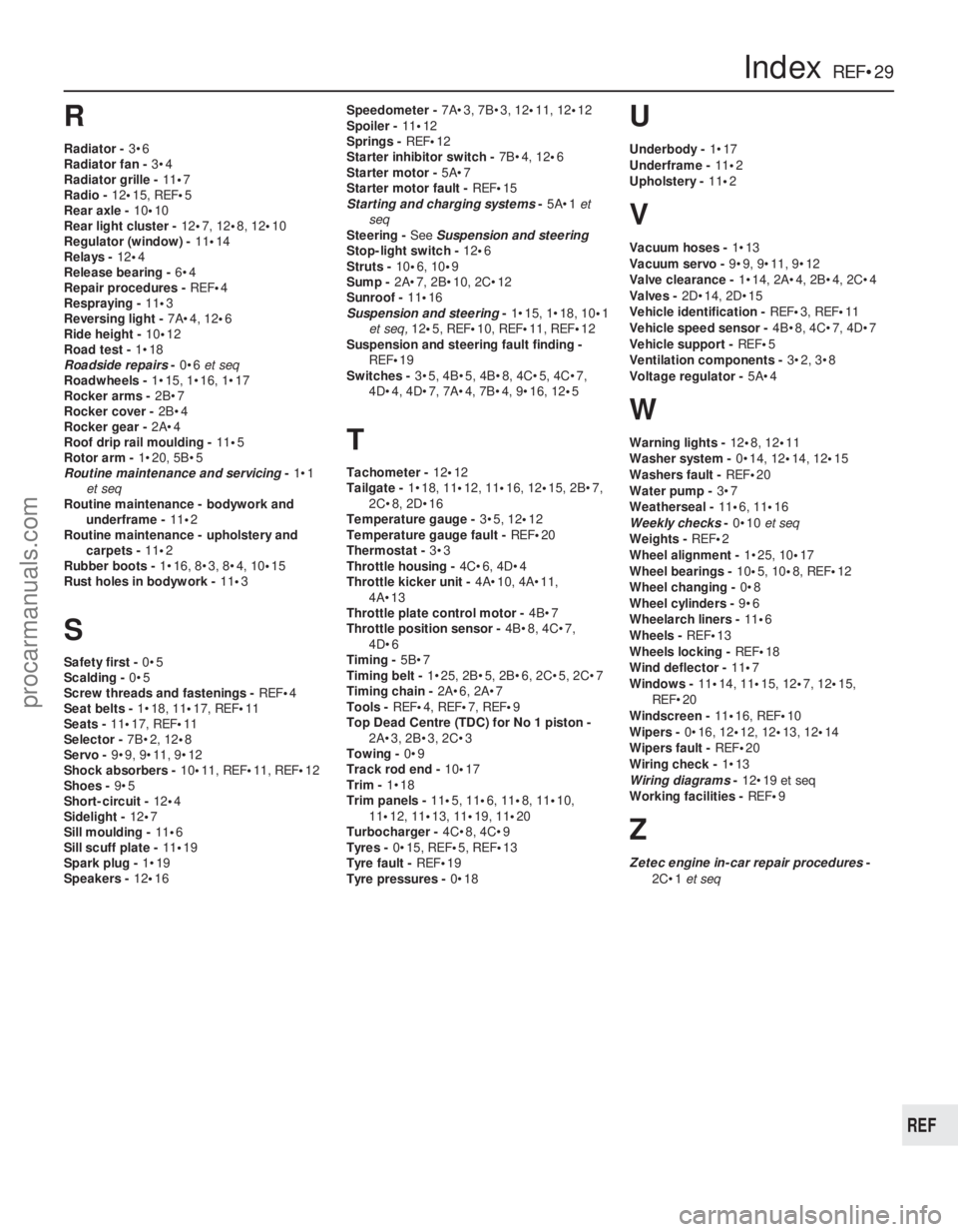
R
Radiator -3•6
Radiator fan - 3•4
Radiator grille - 11•7
Radio - 12•15, REF •5
Rear axle - 10•10
Rear light cluster - 12•7, 12•8, 12 •10
Regulator (window) - 11•14
Relays - 12•4
Release bearing - 6•4
Repair procedures - REF•4
Respraying - 11•3
Reversing light - 7A•4, 12•6
Ride height - 10•12
Road test - 1•18
Roadside repairs -0•6 et seq
Roadwheels - 1•15, 1•16, 1•17
Rocker arms - 2B•7
Rocker cover - 2B•4
Rocker gear - 2A•4
Roof drip rail moulding - 11•5
Rotor arm - 1•20, 5B•5
Routine maintenance and servicing -1•1
et seq
Routine maintenance - bodywork and
underframe - 11•2
Routine maintenance - upholstery and carpets - 11•2
Rubber boots - 1•16, 8•3, 8•4, 10 •15
Rust holes in bodywork - 11•3
S
Safety first - 0•5
Scalding - 0•5
Screw threads and fastenings - REF•4
Seat belts - 1•18, 11•17, REF•11
Seats - 11•17, REF •11
Selector - 7B•2, 12•8
Servo - 9•9, 9•11, 9•12
Shock absorbers - 10•11, REF •11, REF•12
Shoes - 9•5
Short-circuit - 12•4
Sidelight - 12•7
Sill moulding - 11•6
Sill scuff plate - 11•19
Spark plug - 1•19
Speakers - 12•16 Speedometer -
7A•3, 7B•3, 12•11, 12•12
Spoiler - 11•12
Springs - REF•12
Starter inhibitor switch - 7B•4, 12•6
Starter motor - 5A•7
Starter motor fault - REF•15
Starting and charging systems -5A•1 et
seq
Steering - See Suspension and steering
Stop-light switch - 12•6
Struts - 10•6, 10• 9
Sump - 2A•7, 2B•10, 2C•12
Sunroof - 11•16
Suspension and steering -1•15, 1•18, 10 •1
et seq, 12•5, REF •10, REF •11, REF• 12
Suspension and steering fault finding -
REF •19
Switches - 3•5, 4B•5, 4B•8, 4C•5, 4C•7,
4D•4, 4D•7, 7A•4, 7B•4, 9•16, 12 •5
T
Tachometer - 12•12
Tailgate - 1•18, 11•12, 11•16, 12•15, 2B•7,
2C•8, 2D•16
Temperature gauge - 3•5, 12•12
Temperature gauge fault - REF•20
Thermostat - 3•3
Throttle housing - 4C•6, 4D•4
Throttle kicker unit - 4A•10, 4A•11,
4A•13
Throttle plate control motor - 4B•7
Throttle position sensor - 4B•8, 4C•7,
4D•6
Timing - 5B•7
Timing belt - 1•25, 2B•5, 2B•6, 2C•5, 2C•7
Timing chain - 2A•6, 2A•7
Tools - REF•4, REF•7, REF•9
Top Dead Centre (TDC) for No 1 piston - 2A•3, 2B•3, 2C•3
Towing - 0•9
Track rod end - 10•17
Trim - 1•18
Trim panels - 11•5, 11 •6, 11•8, 11 •10,
11 •12, 11•13, 11•19, 11•20
Turbocharger - 4C•8, 4C•9
Tyres - 0•15, REF•5, REF •13
Tyre fault - REF•19
Tyre pressures - 0•18
U
Underbody -1•17
Underframe - 11•2
Upholstery - 11•2
V
Vacuum hoses - 1•13
Vacuum servo - 9•9, 9•11, 9•12
Valve clearance - 1•14, 2A•4, 2B•4, 2C•4
Valves - 2D•14, 2D•15
Vehicle identification - REF•3, REF •11
Vehicle speed sensor - 4B•8, 4C•7, 4D•7
Vehicle support - REF•5
Ventilation components - 3•2, 3•8
Voltage regulator - 5A•4
W
Warning lights - 12•8, 12•11
Washer system - 0•14, 12•14, 12•15
Washers fault - REF•20
Water pump - 3•7
Weatherseal - 11•6, 11•16
Weekly checks -0•10 et seq
Weights - REF•2
Wheel alignment - 1•25, 10•17
Wheel bearings - 10•5, 10 •8, REF •12
Wheel changing - 0•8
Wheel cylinders - 9•6
Wheelarch liners - 11•6
Wheels - REF•13
Wheels locking - REF•18
Wind deflector - 11•7
Windows - 11•14, 11•15, 12 •7, 12•15,
REF•20
Windscreen - 11•16, REF •10
Wipers - 0•16, 12• 12, 12•13, 12•14
Wipers fault - REF•20
Wiring check - 1•13
Wiring diagrams - 12•19 et seq
Working facilities - REF•9
Z
Zetec engine in-car repair procedures -
2C•1 et seq
IndexREF•29
REF
1595 Ford Fiesta Remakeprocarmanuals.com
http://vnx.su