1989 FORD FIESTA recommended oil
[x] Cancel search: recommended oilPage 91 of 296
necessary for reassembly of the engine are at
hand. In addition to all normal tools and
materials, jointing and thread locking
compound will be needed during engine
reassembly. For general-purpose applications,
it is recommended that Loctite 275 setting
sealer or Hylomar PL32M non-setting sealer
be used for joints where required, and
Loctite 270 for stud and bolt thread-locking.
For specific applications on Zetec engines,
Hylosil 102 for the cylinder block/crankcase-
to-sump/oil pump/oil seal carrier joints, and
Loctite 518 for the camshaft right-hand
bearing caps should be used. These are
recommended by, and obtained from, Ford
dealers. In all other cases, provided the
relevant mating surfaces are clean and flat,
new gaskets will be sufficient to ensure joints
are oil-tight. Do notuse any kind of silicone-
based sealant on any part of the fuel system or
inlet manifold, and neveruse exhaust sealants
upstream of the catalytic converter.
2 In order to save time and avoid problems,
engine reassembly can be carried out in the
following order (as applicable).
a) Engine ventilation cap (CVH and PTE engines).
b) Tappets and camshaft (HCS engines).
c) Crankshaft and main bearings.
d) Pistons and connecting rods.
e) Oil pump.
f) Sump.
g) Flywheel/driveplate.
h) Cylinder head.
i) Timing sprockets and chain/belt.
j) Engine external components.
3 Ensure that everything is clean prior to
reassembly. As mentioned previously, dirt and
metal particles can quickly destroy bearings
and result in major engine damage. Use clean
engine oil to lubricate during reassembly.
16 Piston rings - refitting
2
1Before installing new piston rings, check
the end gaps. Lay out each piston set with a
piston/connecting rod assembly, and keep them together as a matched set from now on.
2
Insert the top compression ring into the first
cylinder, and square it up with the cylinder
walls by pushing it in with the top of the
piston. The ring should be near the bottom of
the cylinder, at the lower limit of ring travel.
3 To measure the end gap, slip feeler gauges
between the ends of the ring, until a gauge
equal to the gap width is found. The feeler
gauge should slide between the ring ends
with a slight amount of drag. Compare the
measurement to the value given in the
Specifications in this Chapter; if the gap is
larger or smaller than specified, double-check to make sure you have the correct rings
before proceeding. If you are assessing the
condition of used rings, have the cylinder
bores checked and measured by a Ford
dealer or similar engine reconditioning
specialist, so that you can be sure of exactly
which component is worn, and seek advice as
to the best course of action to take.
4 If the end gap is still too small, it must be
opened up by careful filing of the ring ends
using a fine file. If it is too large, this is not as
serious, unless the specified limit is exceeded,
in which case very careful checking is
required of the dimensions of all components,
as well as of the new parts.
5 Repeat the procedure for each ring that will
be installed in the first cylinder, and for each
ring in the remaining cylinders. Remember to
keep rings, pistons and cylinders matched up.
6 Refit the piston rings as follows. Where the
original rings are being refitted, use the marks
or notes made on removal, to ensure that
each ring is refitted to its original groove and
the same way up. New rings generally have
their top surfaces identified by markings
(often an indication of size, such as “STD”, or
the word “TOP”) - the rings must be fitted with
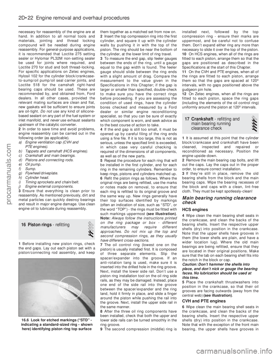
such markings uppermost (see illustration) .
Note: Always follow the instructions printed
on the ring package or box - different
manufacturers may require different
approaches. Do not mix up the top and
second compression rings, as they usually
have different cross-sections.
7 The oil control ring (lowest one on the
piston) is usually installed first. It is composed
of three separate elements. Slip the
spacer/expander into the groove. If an
anti- rotation tang is used, make sure it is
inserted into the drilled hole in the ring groove.
Next, install the lower side rail. Don’t use a
piston ring installation tool on the oil ring side
rails, as they may be damaged. Instead, place
one end of the side rail into the groove
between the spacer/expander and the ring
land, hold it firmly in place, and slide a finger
around the piston while pushing the rail into
the groove. Next, install the upper side rail in
the same manner.
8 After the three oil ring components have
been installed, check that both the upper and
lower side rails can be turned smoothly in the
ring groove.
9 The second compression (middle) ring is installed next, followed by the top
compression ring - ensure their marks are
uppermost, and be careful not to confuse
them. Don’t expand either ring any more than
necessary to slide it over the top of the piston.
10
On HCS engines, when all of the rings are
fitted to each piston, arrange them so that the
gaps are positioned as described in the
Specifications at the start of this Chapter.
11 On the CVH and PTE engines, when all of
the rings are fitted to each piston, arrange
them so that the gaps are spaced at 120º
intervals, with no gaps positioned above the
gudgeon pin hole.
12 On Zetec engines, when all the rings are
fitted to each piston, space the ring gaps
(including the elements of the oil control ring)
uniformly around the piston at 120º intervals.
17 Crankshaft - refitting and
main bearing running
clearance check
4
1 It is assumed at this point that the cylinder
block/crankcase and crankshaft have been
cleaned, inspected and repaired or
reconditioned as necessary. Position the
engine upside-down.
2 Remove the main bearing cap bolts, and lift
out the caps. Lay the caps out in the proper
order, to ensure correct installation.
3 If they’re still in place, remove the old
bearing shells from the block and the main
bearing caps. Wipe the bearing recesses of
the block and caps with a clean, lint-free
cloth. They must be kept spotlessly-clean!
Main bearing running clearance
check
HCS engines
4 Wipe clean the main bearing shell seats in
the crankcase, and clean the backs of the
bearing shells. Insert the respective upper
shells (dry) into position in the crankcase.
Note that the upper shells have grooves in
them (the lower shells are plain, and have a
wider location lug). Where the old main
bearings are being refitted, ensure that they
are located in their original positions. Make
sure that the tab on each bearing shell fits into
the notch in the block or cap.
Caution: Don’t hammer the shells into
place, and don’t nick or gouge the bearing
faces. No lubrication should be used at
this time.
5 Place the crankshaft thrustwashers into
position in the crankcase, so that their oil
grooves are facing outwards (away from the
central web) (see illustration) .
CVH and PTE engines
6Wipe clean the main bearing shell seats in
the crankcase, and clean the backs of the
bearing shells. Insert the respective upper
shells (dry) into position in the crankcase.
Note that with the exception of the front main
bearing, the upper shells have grooves in
2D•22 Engine removal and overhaul procedures
16.6 Look for etched markings (“STD” -
indicating a standard-sized ring - shown
here) identifying piston ring top surface
1595Ford Fiesta Remakeprocarmanuals.com
http://vnx.su
Page 94 of 296
Plastigauge to the scale printed on the
Plastigauge envelope, to obtain the running
clearance (see illustration 17.15) . Compare it
to the Specifications, to make sure the
clearance is correct.
14 If the clearance is not as specified, seek
the advice of a Ford dealer or similar engine
reconditioning specialist - if the crankshaft
journals are in good condition it may be
possible simply to renew the shells to achieve
the correct clearance. If this is not possible,
the crankshaft must be reground by a
specialist, who can also supply the necessary
undersized shells. First though, make sure
that no dirt or oil was trapped between the
bearing shells and the connecting rod or cap
when the clearance was measured. Also,
recheck the crankpin diameter. If the
Plastigauge was wider at one end than the
other, the crankpin journal may be tapered.
15 Carefully scrape all traces of the
Plastigauge material off the journal and the
bearing surface. Be very careful not to scratch
the bearing - use your fingernail or the edge of a credit card.
Final piston/connecting rod
refitting
16 Make sure the bearing surfaces are
perfectly clean, then apply a uniform layer of
clean molybdenum disulphide-based grease,
engine assembly lubricant, or clean engine oil,
to both of them. You’ll have to push the piston
into the cylinder to expose the bearing surface
of the shell in the connecting rod.
17 Slide the connecting rod back into place
on the crankpin (big-end) journal, refit the big-
end bearing cap, and then tighten the bolts as
described above.
18 Repeat the entire procedure for the
remaining piston/connecting rod assemblies.
19 The important points to remember are:
a) Keep the backs of the bearing shells and the recesses of the connecting rods and
caps perfectly clean when assembling
them.
b) Make sure you have the correct
piston/rod assembly for each cylinder -
use the etched cylinder numbers to
identify the front-facing side of both the
rod and its cap.
c) The arrow on the piston crown must face the timing belt/chain end of the engine.
d) Lubricate the cylinder bores with clean
engine oil.
e) Lubricate the bearing surfaces when refitting the big-end bearing caps after the
running clearance has been checked. 20
After all the piston/connecting rod
assemblies have been properly installed,
rotate the crankshaft a number of times by
hand, to check for any obvious binding.
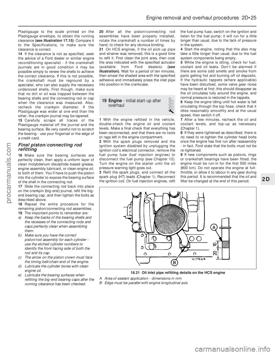
21 On HCS engines, if the oil pick-up pipe
and strainer was removed, this is a good time
to refit it. First clean the joint area, then coat
the area indicated with the specified activator
(available from Ford dealers) (see
illustration) . Wait for a period of ten minutes,
then smear the shaded area with the specified
adhesive and immediately press the inlet pipe
into position in the crankcase.
19 Engine - initial start-up after
overhaul
1
1 With the engine refitted in the vehicle,
double-check the engine oil and coolant
levels. Make a final check that everything has
been reconnected, and that there are no tools
or rags left in the engine compartment.
2 With the spark plugs removed and the
ignition system disabled by unplugging the
ignition coil’s electrical connector, remove the
fuel pump fuse (fuel injection engines) to
disconnect the fuel pump (see Chapter 12).
Turn the engine on the starter until the oil
pressure warning light goes out.
3 Refit the spark plugs, and connect all the
spark plug (HT) leads (Chapter 1). Reconnect
the ignition coil. On fuel injection engines, refit the fuel pump fuse, switch on the ignition and
listen for the fuel pump; it will run for a little
longer than usual, due to the lack of pressure
in the system.
4
Start the engine, noting that this also may
take a little longer than usual, due to the fuel
system components being empty.
5 While the engine is idling, check for fuel,
coolant and oil leaks. Don’t be alarmed if
there are some odd smells and smoke from
parts getting hot and burning off oil deposits.
If the hydraulic tappets (where applicable)
have been disturbed, some valve gear noise
may be heard at first; this should disappear as
the oil circulates fully around the engine, and
normal pressure is restored in the tappets.
6 Keep the engine idling until hot water is felt
circulating through the top hose, check that it
idles reasonably smoothly and at the usual
speed, then switch it off.
7 After a few minutes, recheck the oil and
coolant levels, and top-up as necessary
(Chapter 1).
8 If they were tightened as described, there is
no need to re-tighten the cylinder head bolts
once the engine has first run after reassembly
- in fact, Ford state that the bolts must notbe
re-tightened.
9 If new components such as pistons, rings
or crankshaft bearings have been fitted, the
engine must be run-in for the first 500 miles
(800 km). Do not operate the engine at full-
throttle, or allow it to labour in any gear during
this period. It is recommended that the oil and
filter be changed at the end of this period.
Engine removal and overhaul procedures 2D•25
18.21 Oil inlet pipe refitting details on the HCS engine
A Area of sealant application - dimensions in mm
B Edge must be parallel with engine longitudinal axis
2D
1595Ford Fiesta Remakeprocarmanuals.com
http://vnx.su
Page 97 of 296

Torque wrench settingsNmlbf ft
Thermostat housing to cylinder head: HCS engines . . . . . . . . . . . . . . . . . . . . . . . . . . . . . . . . . . . .\
. . . . . . . . 17 to 21 13 to 16
CVH engines . . . . . . . . . . . . . . . . . . . . . . . . . . . . . . . . . . . .\
. . . . . . . . 9 to 12 7 to 9
PTE engines . . . . . . . . . . . . . . . . . . . . . . . . . . . . . . . . . . . .\
. . . . . . . . 9 7
Zetec engines . . . . . . . . . . . . . . . . . . . . . . . . . . . . . . . . . . . .\
. . . . . . . 17 to 21 13 to 16
Water outlet to thermostat housing (Zetec engines) . . . . . . . . . . . . . . . 9 to 12 7 to 9
Water pump pulley . . . . . . . . . . . . . . . . . . . . . . . . . . . . . . . . . . . .\
. . . . . 107.5
Water pump retaining bolts: HCS, CVH and PTE engines . . . . . . . . . . . . . . . . . . . . . . . . . . . . . . . . 8 6
Zetec engines . . . . . . . . . . . . . . . . . . . . . . . . . . . . . . . . . . . .\
. . . . . . . 1813
Coolant temperature gauge sender . . . . . . . . . . . . . . . . . . . . . . . . . . . . 6 4
Coolant temperature sensor: HCS engines . . . . . . . . . . . . . . . . . . . . . . . . . . . . . . . . . . . .\
. . . . . . . . 2317
CVH engines: 1.4 litre models . . . . . . . . . . . . . . . . . . . . . . . . . . . . . . . . . . . .\
. . . . 1914
1.6 litre models . . . . . . . . . . . . . . . . . . . . . . . . . . . . . . . . . . . .\
. . . . 1511
PTE engines . . . . . . . . . . . . . . . . . . . . . . . . . . . . . . . . . . . .\
. . . . . . . . 1511
Zetec engines . . . . . . . . . . . . . . . . . . . . . . . . . . . . . . . . . . . .\
. . . . . . . 1511
Radiator mounting bolts . . . . . . . . . . . . . . . . . . . . . . . . . . . . . . . . . . . .\
. 20 to 27 15 to 20
Radiator cooling fan shroud retaining bolt . . . . . . . . . . . . . . . . . . . . . . . 3 to 5 2 to 4
Radiator cooling fan motor to shroud nuts . . . . . . . . . . . . . . . . . . . . . . . 9 to 12 7 to 9
Automatic transmission fluid cooling pipe connections to radiator . . . . 17 to 21 13 to 16
3•2 Cooling, heating and ventilation systems
1595Ford Fiesta Remake
1 General information and
precautions
Engine cooling system
The cooling system is of the pressurised
type consisting of a belt-driven pump,
aluminium crossflow radiator, expansion tank,
electric cooling fan and a thermostat. The
system functions as follows. Cold coolant in
the bottom of the radiator passes through the
bottom hose to the water pump, where it is
pumped around the cylinder block and head
passages. After cooling the cylinder bores,
combustion surfaces and valve seats, the
coolant reaches the underside of the
thermostat, which is initially closed. The
coolant passes through the heater and
inlet manifold and is returned to the water
pump. When the engine is cold, the coolant
circulates through the cylinder block, cylinder
head, heater and inlet manifold. When the
coolant reaches a predetermined tempera-
ture, the thermostat opens, and the coolant
then passes through the top hose to
the radiator. As the coolant circulates
through the radiator, it is cooled by the inrush
of air when the car is in forward motion.
Airflow is supplemented by the action of the
electric cooling fan when necessary. Upon
reaching the bottom of the radiator, the
coolant is now cooled, and the cycle is
repeated. When the engine is at normal operating
temperature, the coolant expands, and some
of it is displaced into the expansion tank. This
coolant collects in the tank, and is returned to
the radiator when the system cools.
The electric cooling fan, mounted behind
the radiator, is controlled by a thermostatic switch. At a predetermined coolant
temperature, the switch contacts close, thus
actuating the fan.
Heating/ventilation system
The heating system consists of a blower fan
and heater matrix (radiator) located in the
heater unit, with hoses connecting the heater
matrix to the engine cooling system. Hot
engine coolant is circulated through the
heater matrix. Air is forced through the matrix
by the three-speed fan, dispersing the heat
into the vehicle interior. Fresh air enters the
vehicle through the grille slats between the
windscreen and the rear edge of the bonnet,
and passes through to the heater casing.
Depending on the position of the heater slide
controls, which actuate cable-controlled flap
valves within the heater casing, the air is
distributed, either heated or unheated, via the
ducting to outlet vents. The main outlet vents
in the facia are adjustable. The airflow passes
through the passenger compartment to exit at
the rear of the vehicle.
Precautions
Warning: DO NOT attempt to
remove the expansion tank filler
cap, or to disturb any part of the
cooling system, while it or the
engine is hot, as there is a very great risk
of scalding. If the expansion tank filler cap
must be removed before the engine and
radiator have fully cooled down (even
though this is not recommended) the
pressure in the cooling system must first
be released. Cover the cap with a thick
layer of cloth, to avoid scalding, and slowly
unscrew the filler cap until a hissing sound
can be heard. When the hissing has
stopped, showing that pressure is
released, slowly unscrew the filler cap
further until it can be removed; if more
hissing sounds are heard, wait until they have stopped before unscrewing the cap
completely. At all times, keep well away
from the filler opening.
Warning: Do not allow antifreeze
to come in contact with your
skin, or with the painted
surfaces of the vehicle. Rinse off
spills immediately with plenty of water.
Never leave antifreeze lying around in an
open container, or in a puddle in the
driveway or on the garage floor. Children
and pets are attracted by its sweet smell,
but antifreeze can be fatal if ingested. Warning: If the engine is hot, the
electric cooling fan may start
rotating even if the engine is not
running, so be careful to keep
hands, hair and loose clothing well clear
when working in the engine compartment.
2 Antifreeze -
general information
Note: Refer to the warnings given in Section 1
of this Chapter before proceeding. The cooling system should be filled with a
water/ethylene glycol-based antifreeze
solution, of a strength which will prevent
freezing down to at least -25ºC, or lower if the
local climate requires it. Antifreeze also
provides protection against corrosion, and
increases the coolant boiling point. The cooling system should be maintained
according to the schedule described in
Chapter 1. If antifreeze is used that is not to
Ford’s specification, old or contaminated
coolant mixtures are likely to cause damage,
and encourage the formation of corrosion and
scale in the system. Use distilled water with the
antifreeze, if available - if not, be sure to use
only soft water. Clean rainwater is suitable.
procarmanuals.com
http://vnx.su
Page 108 of 296
1 General information andprecautions
General information
The fuel system on all models with
carburettor induction comprises a rear-
mounted fuel tank, a mechanical diaphragm
fuel pump, a carburettor and an air cleaner. The fuel tank is mounted at the rear, under
the floorpan behind the rear seats. The tank
has a “ventilation-to-atmosphere system”
through a combined roll-over/anti-trickle fill
valve assembly, located in the left-hand rear
wheel arch. A filler neck sensing pipe, integral
with the fuel tank filler pipe, will shut off the
petrol pump filler gun when the predetermined
maximum level of fuel is reached in the tank,
so preventing spillage and wastage. A
conventional fuel level sender unit is mounted
in the top face of the fuel tank. One of two fuel pump types will be fitted,
depending on the engine type. On HCS
engines, the fuel pump is operated by a
pivoting rocker arm; one end rests on an
eccentric lobe on the engine camshaft, and
the other end is attached to the fuel pump
diaphragm. The pump fitted to the CVH
engine is operated by a separate pushrod,
one end rests on an eccentric lobe on the
engine camshaft, and the other rests on the
pump actuating rod which operates the
diaphragm. Both types of mechanical pump
incorporate a nylon mesh filter, and are of
sealed type (they cannot be serviced or
overhauled). Four different types of Weber carburettor
are featured in the range, further details being
given in later Sections of this Chapter. The air cleaner incorporates a “waxstat”
controlled air inlet, supplying either hot air
from a shroud mounted around the exhaust
manifold, or cool air from a duct in the front of
the vehicle.
Precautions
Warning: Petrol is extremely
flammable - great care must be
taken when working on any part of the fuel system. Do not smoke or allow
any naked flames or uncovered light bulbs
near the work area. Note that gas powered
domestic appliances with pilot flames,
such as heaters, boilers and tumble
dryers, also present a fire hazard - bear
this in mind if you are working in an area
where such appliances are present.
Always keep a suitable fire extinguisher
close to the work area and familiarise
yourself with its operation before starting
work. Wear eye protection when working
on fuel systems and wash off any fuel spilt
on bare skin immediately with soap and
water. Note that fuel vapour is just as
dangerous as liquid fuel; a vessel that has
just been emptied of liquid fuel will still
contain vapour and can be potentially
explosive. Petrol is a highly dangerous and
volatile liquid, and the precautions
necessary when handling it cannot be
overstressed.
Many of the operations described in this
Chapter involve the disconnection of fuel
lines, which may cause an amount of fuel
spillage. Before commencing work, refer
to the above Warning and the information
in “Safety first” at the beginning of this
manual.
When working with fuel system
components, pay particular attention to
cleanliness - dirt entering the fuel system
may cause blockages which will lead to
poor running.
Certain adjustment points in the fuel system
are protected by tamperproof caps, plugs or
seals. In some territories, it is an offence to
drive a vehicle with broken or missing
tamperproof seals. Before disturbing a
tamperproof seal, first check that no local or
national laws will be broken by doing so, and
fit a new tamperproof seal after adjustment is
complete, where required by law. Do not
break tamperproof seals on any vehicle whilst
it is still under warranty. Carburettors are delicate instruments, and
care must be taken not to disturb any
components unnecessarily. Before attempting
work on a carburettor, ensure that the relevant
spares are available; it should be noted that a complete strip down of a carburettor is
unlikely to cure a fault which is not
immediately obvious, without introducing new
problems. If persistent problems occur, it is
recommended that the services of a Ford
dealer or a carburettor specialist are sought.
Most dealers will be able to provide
carburettor rejetting and servicing facilities.
Where necessary, it may be possible to
purchase a reconditioned carburettor.
2 Air cleaner
-
removal and refitting
1
Note: Air cleaner element renewal and air
cleaner temperature control system checks
are described in Chapter 1.
Removal
1 Disconnect the battery negative (earth) lead
(refer to Chapter 5A, Section 1).
2 On CVH engine models, pull free and
release the accelerator cable from the locating
clip on the side of the air cleaner.
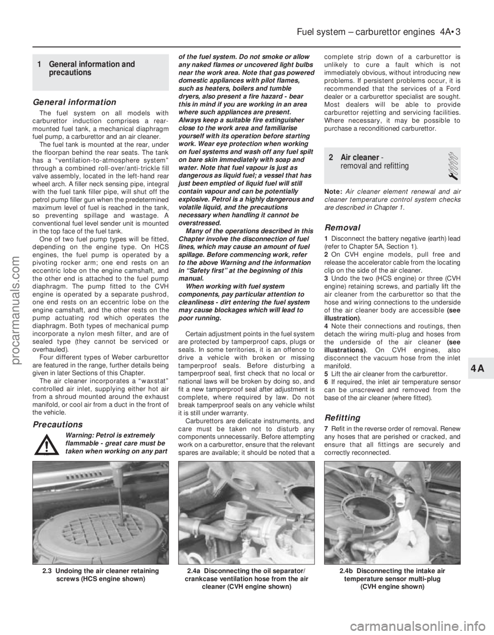
3 Undo the two (HCS engine) or three (CVH
engine) retaining screws, and partially lift the
air cleaner from the carburettor so that the
hose and wiring connections to the underside
of the air cleaner body are accessible (see
illustration) .
4 Note their connections and routings, then
detach the wiring multi-plug and hoses from
the underside of the air cleaner (see
illustrations) . On CVH engines, also
disconnect the vacuum hose from the inlet
manifold.
5 Lift the air cleaner from the carburettor.
6 If required, the inlet air temperature sensor
can be unscrewed and removed from the
base of the air cleaner (where fitted).
Refitting
7 Refit in the reverse order of removal. Renew
any hoses that are perished or cracked, and
ensure that all fittings are securely and
correctly reconnected.
Fuel system – carburettor engines 4A•3
2.4b Disconnecting the intake air temperature sensor multi-plug
(CVH engine shown)2.4a Disconnecting the oil separator/
crankcase ventilation hose from the air
cleaner (CVH engine shown)2.3 Undoing the air cleaner retainingscrews (HCS engine shown)
4A
1595Ford Fiesta Remakeprocarmanuals.com
http://vnx.su
Page 121 of 296
tachometer and an exhaust gas analyser (CO
meter) will be required.
1Check that the idle speed and mixture
settings are as specified (as described in
Chapter 1). These must be correct before
checking/adjusting the fast-idle speed.
2 Switch the engine off, then remove the air
cleaner as described in Section 2.
3 With the engine at its normal operating
temperature and a tachometer connected in
accordance with its manufacturer’s
instructions, hold the throttle linkage partly
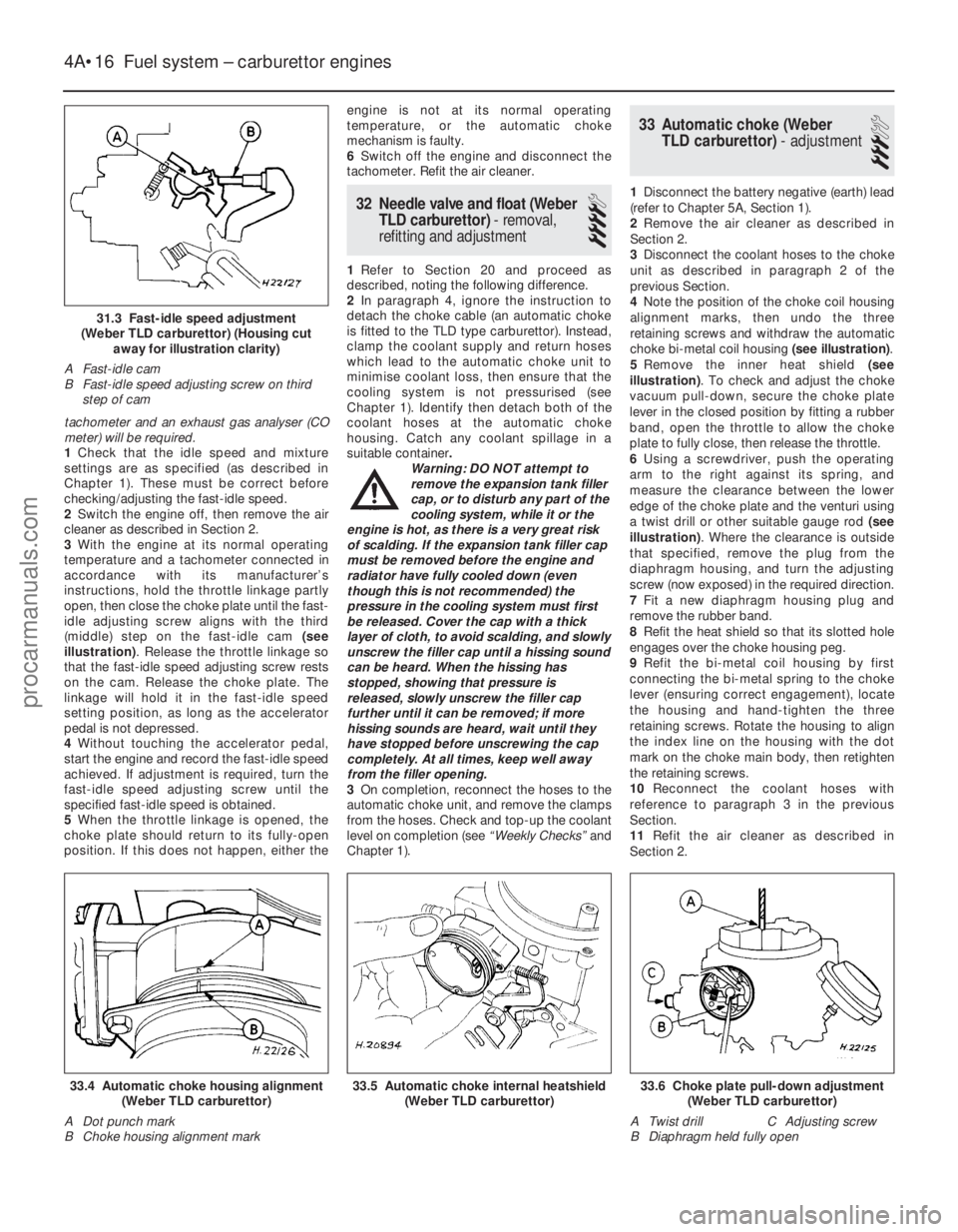
open, then close the choke plate until the fast-
idle adjusting screw aligns with the third
(middle) step on the fast-idle cam (see
illustration) . Release the throttle linkage so
that the fast-idle speed adjusting screw rests
on the cam. Release the choke plate. The
linkage will hold it in the fast-idle speed
setting position, as long as the accelerator
pedal is not depressed.
4 Without touching the accelerator pedal,
start the engine and record the fast-idle speed
achieved. If adjustment is required, turn the
fast-idle speed adjusting screw until the
specified fast-idle speed is obtained.
5 When the throttle linkage is opened, the
choke plate should return to its fully-open
position. If this does not happen, either the engine is not at its normal operating
temperature, or the automatic choke
mechanism is faulty.
6
Switch off the engine and disconnect the
tachometer. Refit the air cleaner.
32 Needle valve and float (Weber
TLD carburettor) - removal,
refitting and adjustment
4
1 Refer to Section 20 and proceed as
described, noting the following difference.
2 In paragraph 4, ignore the instruction to
detach the choke cable (an automatic choke
is fitted to the TLD type carburettor). Instead,
clamp the coolant supply and return hoses
which lead to the automatic choke unit to
minimise coolant loss, then ensure that the
cooling system is not pressurised (see
Chapter 1). Identify then detach both of the
coolant hoses at the automatic choke
housing. Catch any coolant spillage in a
suitable container .
Warning: DO NOT attempt to
remove the expansion tank filler
cap, or to disturb any part of the
cooling system, while it or the
engine is hot, as there is a very great risk
of scalding. If the expansion tank filler cap
must be removed before the engine and
radiator have fully cooled down (even
though this is not recommended) the
pressure in the cooling system must first
be released. Cover the cap with a thick
layer of cloth, to avoid scalding, and slowly
unscrew the filler cap until a hissing sound
can be heard. When the hissing has
stopped, showing that pressure is
released, slowly unscrew the filler cap
further until it can be removed; if more
hissing sounds are heard, wait until they
have stopped before unscrewing the cap
completely. At all times, keep well away
from the filler opening.
3 On completion, reconnect the hoses to the
automatic choke unit, and remove the clamps
from the hoses. Check and top-up the coolant
level on completion (see “Weekly Checks”and
Chapter 1).
33 Automatic choke (Weber TLD carburettor) - adjustment
3
1Disconnect the battery negative (earth) lead
(refer to Chapter 5A, Section 1).
2 Remove the air cleaner as described in
Section 2.
3 Disconnect the coolant hoses to the choke
unit as described in paragraph 2 of the
previous Section.
4 Note the position of the choke coil housing
alignment marks, then undo the three
retaining screws and withdraw the automatic
choke bi-metal coil housing (see illustration).
5 Remove the inner heat shield (see
illustration) . To check and adjust the choke
vacuum pull-down, secure the choke plate
lever in the closed position by fitting a rubber
band, open the throttle to allow the choke
plate to fully close, then release the throttle.
6 Using a screwdriver, push the operating
arm to the right against its spring, and
measure the clearance between the lower
edge of the choke plate and the venturi using
a twist drill or other suitable gauge rod (see
illustration) . Where the clearance is outside
that specified, remove the plug from the
diaphragm housing, and turn the adjusting
screw (now exposed) in the required direction.
7 Fit a new diaphragm housing plug and
remove the rubber band.
8 Refit the heat shield so that its slotted hole
engages over the choke housing peg.
9 Refit the bi-metal coil housing by first
connecting the bi-metal spring to the choke
lever (ensuring correct engagement), locate
the housing and hand-tighten the three
retaining screws. Rotate the housing to align
the index line on the housing with the dot
mark on the choke main body, then retighten
the retaining screws.
10 Reconnect the coolant hoses with
reference to paragraph 3 in the previous
Section.
11 Refit the air cleaner as described in
Section 2.
4A•16 Fuel system – carburettor engines
33.6 Choke plate pull-down adjustment (Weber TLD carburettor)
A Twist drill C Adjusting screw
B Diaphragm held fully open33.5 Automatic choke internal heatshield (Weber TLD carburettor)33.4 Automatic choke housing alignment(Weber TLD carburettor)
A Dot punch mark
B Choke housing alignment mark
1595Ford Fiesta Remake
31.3 Fast-idle speed adjustment
(Weber TLD carburettor) (Housing cut away for illustration clarity)
A Fast-idle cam
B Fast-idle speed adjusting screw on third step of cam
procarmanuals.com
http://vnx.su
Page 122 of 296
34 Automatic choke (WeberTLD carburettor) - removal,
inspection and refitting
4
Note: Refer to the warning note in Section 1
before proceeding. A new carburettor upper
body gasket will be required when
reassembling. On completion, a tachometer
will be required to check the fast-idle speed
adjustment.
Removal
1 Disconnect the battery negative (earth) lead
(refer to Chapter 5A, Section 1).
2 Remove the air cleaner as described in
Section 2.
3 To prevent excess coolant loss, clamp the
coolant supply and return hoses to the
automatic choke unit, and ensure that the
cooling system is not pressurised (see
Chapter 1). Identify then detach both of the
coolant hoses at the automatic choke
housing. Catch any coolant spillage in a
suitable container.
Warning: DO NOT attempt to
remove the expansion tank filler
cap, or to disturb any part of the
cooling system, while it or the
engine is hot, as there is a very great risk
of scalding. If the expansion tank filler cap
must be removed before the engine and
radiator have fully cooled down (even
though this is not recommended) the
pressure in the cooling system must first
be released. Cover the cap with a thick
layer of cloth, to avoid scalding, and slowly
unscrew the filler cap until a hissing sound
can be heard. When the hissing has
stopped, showing that pressure is
released, slowly unscrew the filler cap
further until it can be removed; if more
hissing sounds are heard, wait until they
have stopped before unscrewing the cap
completely. At all times, keep well away
from the filler opening.
4 Detach the fuel pipe and the anti-dieseling
solenoid wiring connector. Any crimped type
hose clips must be replaced with a screw
clamp type clips during reassembly.
5 Unscrew and remove the retaining screws (two conventional, and four Torx type), then lift
the carburettor upper body clear and remove it.
6
Note the position of the choke housing
alignment marks, then undo the three retaining
screws and remove the choke bi-metal coil
unit. Remove the internal heat shield.
7 To remove the automatic choke unit, undo
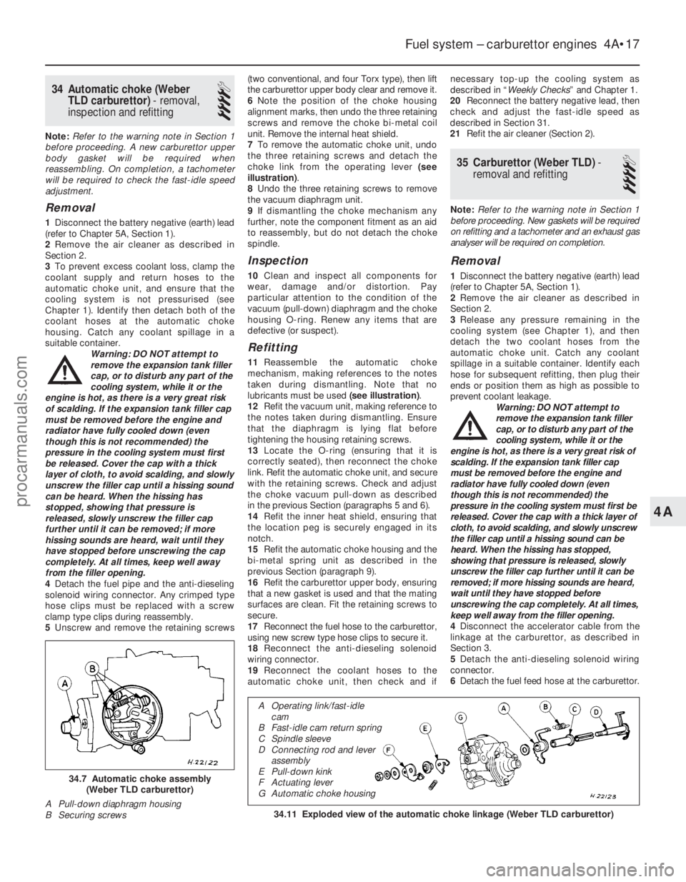
the three retaining screws and detach the
choke link from the operating lever (see
illustration) .
8 Undo the three retaining screws to remove
the vacuum diaphragm unit.
9 If dismantling the choke mechanism any
further, note the component fitment as an aid
to reassembly, but do not detach the choke
spindle.
Inspection
10 Clean and inspect all components for
wear, damage and/or distortion. Pay
particular attention to the condition of the
vacuum (pull-down) diaphragm and the choke
housing O-ring. Renew any items that are
defective (or suspect).
Refitting
11 Reassemble the automatic choke
mechanism, making references to the notes
taken during dismantling. Note that no
lubricants must be used (see illustration).
12 Refit the vacuum unit, making reference to
the notes taken during dismantling. Ensure
that the diaphragm is lying flat before
tightening the housing retaining screws.
13 Locate the O-ring (ensuring that it is
correctly seated), then reconnect the choke
link. Refit the automatic choke unit, and secure
with the retaining screws. Check and adjust
the choke vacuum pull-down as described
in the previous Section (paragraphs 5 and 6).
14 Refit the inner heat shield, ensuring that
the location peg is securely engaged in its
notch.
15 Refit the automatic choke housing and the
bi-metal spring unit as described in the
previous Section (paragraph 9).
16 Refit the carburettor upper body, ensuring
that a new gasket is used and that the mating
surfaces are clean. Fit the retaining screws to
secure.
17 Reconnect the fuel hose to the carburettor,
using new screw type hose clips to secure it.
18 Reconnect the anti-dieseling solenoid
wiring connector.
19 Reconnect the coolant hoses to the
automatic choke unit, then check and if necessary top-up the cooling system as
described in “
Weekly Checks ” and Chapter 1.
20 Reconnect the battery negative lead, then
check and adjust the fast-idle speed as
described in Section 31.
21 Refit the air cleaner (Section 2).
35 Carburettor (Weber TLD) -
removal and refitting
4
Note: Refer to the warning note in Section 1
before proceeding. New gaskets will be required
on refitting and a tachometer and an exhaust gas
analyser will be required on completion.
Removal
1 Disconnect the battery negative (earth) lead
(refer to Chapter 5A, Section 1).
2 Remove the air cleaner as described in
Section 2.
3 Release any pressure remaining in the
cooling system (see Chapter 1), and then
detach the two coolant hoses from the
automatic choke unit. Catch any coolant
spillage in a suitable container. Identify each
hose for subsequent refitting, then plug their
ends or position them as high as possible to
prevent coolant leakage. Warning: DO NOT attempt to
remove the expansion tank filler
cap, or to disturb any part of the
cooling system, while it or the
engine is hot, as there is a very great risk of
scalding. If the expansion tank filler cap
must be removed before the engine and
radiator have fully cooled down (even
though this is not recommended) the
pressure in the cooling system must first be
released. Cover the cap with a thick layer of
cloth, to avoid scalding, and slowly unscrew
the filler cap until a hissing sound can be
heard. When the hissing has stopped,
showing that pressure is released, slowly
unscrew the filler cap further until it can be
removed; if more hissing sounds are heard,
wait until they have stopped before
unscrewing the cap completely. At all times,
keep well away from the filler opening.
4 Disconnect the accelerator cable from the
linkage at the carburettor, as described in
Section 3.
5 Detach the anti-dieseling solenoid wiring
connector.
6 Detach the fuel feed hose at the carburettor.
Fuel system – carburettor engines 4A•17
34.11 Exploded view of the automatic choke linkage (Weber TLD carburet\
tor)
34.7 Automatic choke assembly
(Weber TLD carburettor)
A Pull-down diaphragm housing
B Securing screws
4A
1595Ford Fiesta Remake
A Operating link/fast-idle cam
B Fast-idle cam return spring
C Spindle sleeve
D Connecting rod and lever assembly
E Pull-down kink
F Actuating lever
G Automatic choke housing
procarmanuals.com
http://vnx.su
Page 129 of 296
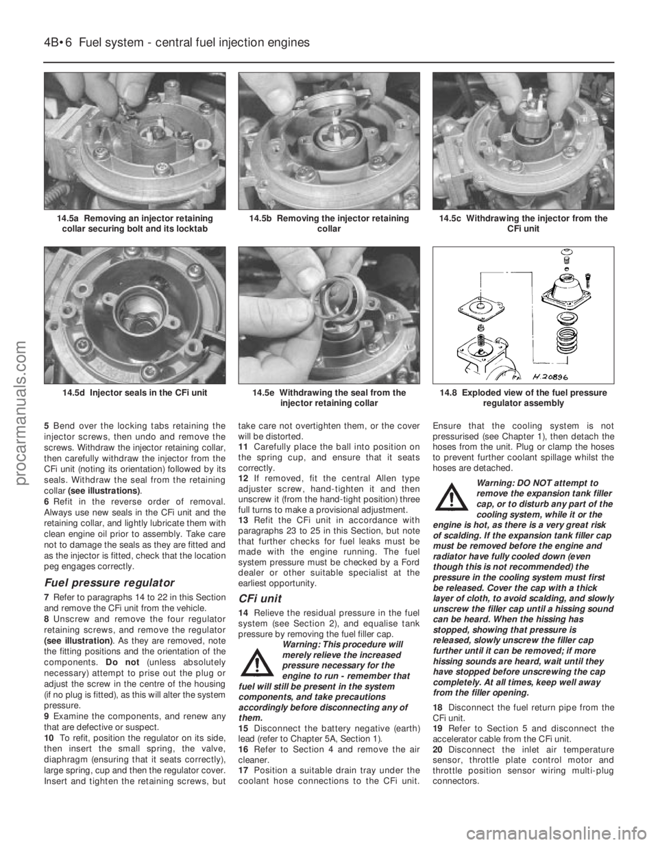
5Bend over the locking tabs retaining the
injector screws, then undo and remove the
screws. Withdraw the injector retaining collar,
then carefully withdraw the injector from the
CFi unit (noting its orientation) followed by its
seals. Withdraw the seal from the retaining
collar (see illustrations) .
6 Refit in the reverse order of removal.
Always use new seals in the CFi unit and the
retaining collar, and lightly lubricate them with
clean engine oil prior to assembly. Take care
not to damage the seals as they are fitted and
as the injector is fitted, check that the location
peg engages correctly.
Fuel pressure regulator
7 Refer to paragraphs 14 to 22 in this Section
and remove the CFi unit from the vehicle.
8 Unscrew and remove the four regulator
retaining screws, and remove the regulator
(see illustration) . As they are removed, note
the fitting positions and the orientation of the
components. Do not(unless absolutely
necessary) attempt to prise out the plug or
adjust the screw in the centre of the housing
(if no plug is fitted), as this will alter the system
pressure.
9 Examine the components, and renew any
that are defective or suspect.
10 To refit, position the regulator on its side,
then insert the small spring, the valve,
diaphragm (ensuring that it seats correctly),
large spring, cup and then the regulator cover.
Insert and tighten the retaining screws, but take care not overtighten them, or the cover
will be distorted.
11
Carefully place the ball into position on
the spring cup, and ensure that it seats
correctly.
12 If removed, fit the central Allen type
adjuster screw, hand-tighten it and then
unscrew it (from the hand-tight position) three
full turns to make a provisional adjustment.
13 Refit the CFi unit in accordance with
paragraphs 23 to 25 in this Section, but note
that further checks for fuel leaks must be
made with the engine running. The fuel
system pressure must be checked by a Ford
dealer or other suitable specialist at the
earliest opportunity.CFi unit
14 Relieve the residual pressure in the fuel
system (see Section 2), and equalise tank
pressure by removing the fuel filler cap. Warning: This procedure will
merely relieve the increased
pressure necessary for the
engine to run - remember that
fuel will still be present in the system
components, and take precautions
accordingly before disconnecting any of
them.
15 Disconnect the battery negative (earth)
lead (refer to Chapter 5A, Section 1).
16 Refer to Section 4 and remove the air
cleaner.
17 Position a suitable drain tray under the
coolant hose connections to the CFi unit. Ensure that the cooling system is not
pressurised (see Chapter 1), then detach the
hoses from the unit. Plug or clamp the hoses
to prevent further coolant spillage whilst the
hoses are detached.
Warning: DO NOT attempt to
remove the expansion tank filler
cap, or to disturb any part of the
cooling system, while it or the
engine is hot, as there is a very great risk
of scalding. If the expansion tank filler cap
must be removed before the engine and
radiator have fully cooled down (even
though this is not recommended) the
pressure in the cooling system must first
be released. Cover the cap with a thick
layer of cloth, to avoid scalding, and slowly
unscrew the filler cap until a hissing sound
can be heard. When the hissing has
stopped, showing that pressure is
released, slowly unscrew the filler cap
further until it can be removed; if more
hissing sounds are heard, wait until they
have stopped before unscrewing the cap
completely. At all times, keep well away
from the filler opening.
18 Disconnect the fuel return pipe from the
CFi unit.
19 Refer to Section 5 and disconnect the
accelerator cable from the CFi unit.
20 Disconnect the inlet air temperature
sensor, throttle plate control motor and
throttle position sensor wiring multi-plug
connectors.
4B•6 Fuel system - central fuel injection engines
14.8 Exploded view of the fuel pressure
regulator assembly14.5e Withdrawing the seal from theinjector retaining collar14.5d Injector seals in the CFi unit
14.5c Withdrawing the injector from the CFi unit14.5b Removing the injector retainingcollar14.5a Removing an injector retainingcollar securing bolt and its locktab
1595Ford Fiesta Remakeprocarmanuals.com
http://vnx.su
Page 141 of 296
15 Inlet manifold-
removal and refitting
4
Note: Refer to the warning note in Section 1
before proceeding.
Removal
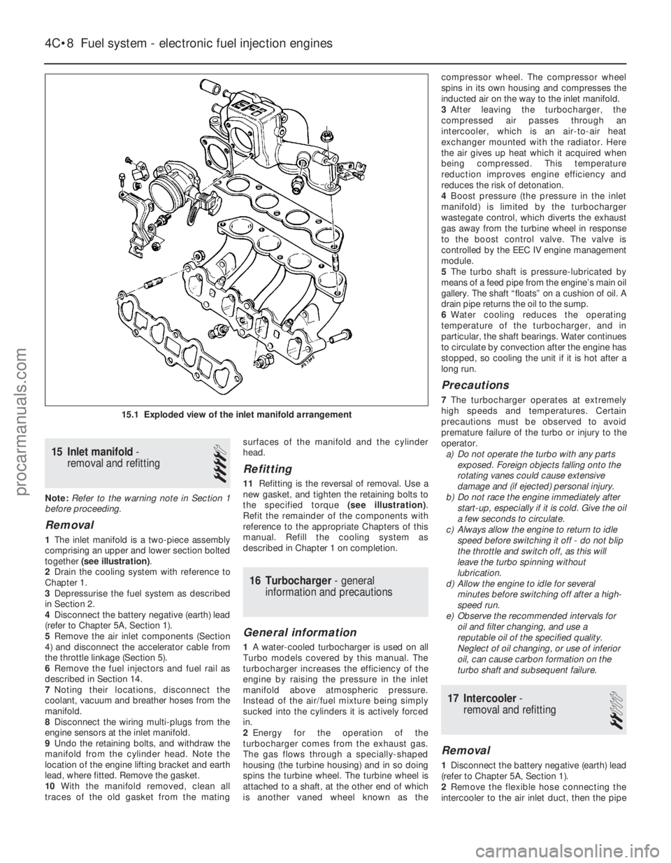
1 The inlet manifold is a two-piece assembly
comprising an upper and lower section bolted
together (see illustration) .
2 Drain the cooling system with reference to
Chapter 1.
3 Depressurise the fuel system as described
in Section 2.
4 Disconnect the battery negative (earth) lead
(refer to Chapter 5A, Section 1).
5 Remove the air inlet components (Section
4) and disconnect the accelerator cable from
the throttle linkage (Section 5).
6 Remove the fuel injectors and fuel rail as
described in Section 14.
7 Noting their locations, disconnect the
coolant, vacuum and breather hoses from the
manifold.
8 Disconnect the wiring multi-plugs from the
engine sensors at the inlet manifold.
9 Undo the retaining bolts, and withdraw the
manifold from the cylinder head. Note the
location of the engine lifting bracket and earth
lead, where fitted. Remove the gasket.
10 With the manifold removed, clean all
traces of the old gasket from the mating surfaces of the manifold and the cylinder
head.
Refitting
11
Refitting is the reversal of removal. Use a
new gasket, and tighten the retaining bolts to
the specified torque (see illustration).
Refit the remainder of the components with
reference to the appropriate Chapters of this
manual. Refill the cooling system as
described in Chapter 1 on completion.
16 Turbocharger - general
information and precautions
General information
1 A water-cooled turbocharger is used on all
Turbo models covered by this manual. The
turbocharger increases the efficiency of the
engine by raising the pressure in the inlet
manifold above atmospheric pressure.
Instead of the air/fuel mixture being simply
sucked into the cylinders it is actively forced
in.
2 Energy for the operation of the
turbocharger comes from the exhaust gas.
The gas flows through a specially-shaped
housing (the turbine housing) and in so doing
spins the turbine wheel. The turbine wheel is
attached to a shaft, at the other end of which
is another vaned wheel known as the compressor wheel. The compressor wheel
spins in its own housing and compresses the
inducted air on the way to the inlet manifold.
3
After leaving the turbocharger, the
compressed air passes through an
intercooler, which is an air-to-air heat
exchanger mounted with the radiator. Here
the air gives up heat which it acquired when
being compressed. This temperature
reduction improves engine efficiency and
reduces the risk of detonation.
4 Boost pressure (the pressure in the inlet
manifold) is limited by the turbocharger
wastegate control, which diverts the exhaust
gas away from the turbine wheel in response
to the boost control valve. The valve is
controlled by the EEC IV engine management
module.
5 The turbo shaft is pressure-lubricated by
means of a feed pipe from the engine’s main oil
gallery. The shaft “floats” on a cushion of oil. A
drain pipe returns the oil to the sump.
6 Water cooling reduces the operating
temperature of the turbocharger, and in
particular, the shaft bearings. Water continues
to circulate by convection after the engine has
stopped, so cooling the unit if it is hot after a
long run.
Precautions
7 The turbocharger operates at extremely
high speeds and temperatures. Certain
precautions must be observed to avoid
premature failure of the turbo or injury to the
operator. a) Do not operate the turbo with any parts
exposed. Foreign objects falling onto the
rotating vanes could cause extensive
damage and (if ejected) personal injury.
b) Do not race the engine immediately after
start-up, especially if it is cold. Give the oil
a few seconds to circulate.
c) Always allow the engine to return to idle
speed before switching it off - do not blip
the throttle and switch off, as this will
leave the turbo spinning without
lubrication.
d) Allow the engine to idle for several
minutes before switching off after a high-
speed run.
e) Observe the recommended intervals for oil and filter changing, and use a
reputable oil of the specified quality.
Neglect of oil changing, or use of inferior
oil, can cause carbon formation on the
turbo shaft and subsequent failure.
17 Intercooler -
removal and refitting
2
Removal
1 Disconnect the battery negative (earth) lead
(refer to Chapter 5A, Section 1).
2 Remove the flexible hose connecting the
intercooler to the air inlet duct, then the pipe
4C•8 Fuel system - electronic fuel injection engines
15.1 Exploded view of the inlet manifold arrangement
1595Ford Fiesta Remakeprocarmanuals.com
http://vnx.su