1989 FORD FIESTA jacking
[x] Cancel search: jackingPage 57 of 296
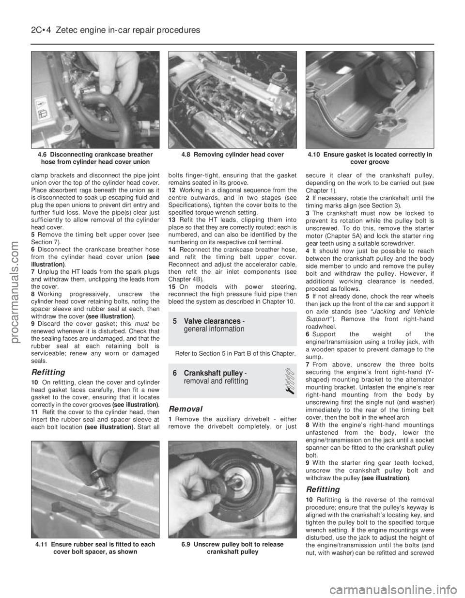
clamp brackets and disconnect the pipe joint
union over the top of the cylinder head cover.
Place absorbent rags beneath the union as it
is disconnected to soak up escaping fluid and
plug the open unions to prevent dirt entry and
further fluid loss. Move the pipe(s) clear just
sufficiently to allow removal of the cylinder
head cover.
5Remove the timing belt upper cover (see
Section 7).
6 Disconnect the crankcase breather hose
from the cylinder head cover union (see
illustration) .
7 Unplug the HT leads from the spark plugs
and withdraw them, unclipping the leads from
the cover.
8 Working progressively, unscrew the
cylinder head cover retaining bolts, noting the
spacer sleeve and rubber seal at each, then
withdraw the cover (see illustration).
9 Discard the cover gasket; this mustbe
renewed whenever it is disturbed. Check that
the sealing faces are undamaged, and that the
rubber seal at each retaining bolt is
serviceable; renew any worn or damaged
seals.
Refitting
10 On refitting, clean the cover and cylinder
head gasket faces carefully, then fit a new
gasket to the cover, ensuring that it locates
correctly in the cover grooves (see illustration).
11 Refit the cover to the cylinder head, then
insert the rubber seal and spacer sleeve at
each bolt location (see illustration). Start allbolts finger-tight, ensuring that the gasket
remains seated in its groove.
12
Working in a diagonal sequence from the
centre outwards, and in two stages (see
Specifications), tighten the cover bolts to the
specified torque wrench setting.
13 Refit the HT leads, clipping them into
place so that they are correctly routed; each is
numbered, and can also be identified by the
numbering on its respective coil terminal.
14 Reconnect the crankcase breather hose,
and refit the timing belt upper cover.
Reconnect and adjust the accelerator cable,
then refit the air inlet components (see
Chapter 4B).
15 On models with power steering,
reconnect the high pressure fluid pipe then
bleed the system as described in Chapter 10.
5 Valve clearances -
general information
Refer to Section 5 in Part B of this Chapter.
6 Crankshaft pulley -
removal and refitting
1
Removal
1 Remove the auxiliary drivebelt - either
remove the drivebelt completely, or just secure it clear of the crankshaft pulley,
depending on the work to be carried out (see
Chapter 1).
2
If necessary, rotate the crankshaft until the
timing marks align (see Section 3).
3 The crankshaft must now be locked to
prevent its rotation while the pulley bolt is
unscrewed. To do this, remove the starter
motor (Chapter 5A) and lock the starter ring
gear teeth using a suitable screwdriver.
4 It should now just be possible to reach
between the crankshaft pulley and the body
side member to undo and remove the pulley
bolt and withdraw the pulley. However, if
additional working clearance is needed,
proceed as follows.
5 If not already done, chock the rear wheels
then jack up the front of the car and support it
on axle stands (see “Jacking and Vehicle
Support” ). Remove the front right-hand
roadwheel.
6 Support the weight of the
engine/transmission using a trolley jack, with
a wooden spacer to prevent damage to the
sump.
7 From above, unscrew the three bolts
securing the engine’s front right-hand (Y-
shaped) mounting bracket to the alternator
mounting bracket. Unfasten the engine’s rear
right-hand mounting from the body by
unscrewing first the single nut (and washer)
immediately to the rear of the timing belt
cover, then the bolt in the wheel arch
8 With the engine’s right-hand mountings
unfastened from the body, lower the
engine/transmission on the jack until a socket
spanner can be fitted to the crankshaft pulley
bolt.
9 With the starter ring gear teeth locked,
unscrew the crankshaft pulley bolt and
withdraw the pulley (see illustration).
Refitting
10Refitting is the reverse of the removal
procedure; ensure that the pulley’s keyway is
aligned with the crankshaft’s locating key, and
tighten the pulley bolt to the specified torque
wrench setting. If the engine mountings were
disturbed, use the jack to adjust the height of
the engine/transmission until the bolts (and
nut, with washer) can be refitted and screwed
2C•4 Zetec engine in-car repair procedures
6.9 Unscrew pulley bolt to release
crankshaft pulley4.11 Ensure rubber seal is fitted to eachcover bolt spacer, as shown
4.10 Ensure gasket is located correctly in cover groove4.8 Removing cylinder head cover
1595Ford Fiesta Remake
4.6 Disconnecting crankcase breather
hose from cylinder head cover unionprocarmanuals.com
http://vnx.su
Page 67 of 296
7Inspect the rotors for obvious signs of wear
or damage, and renew if necessary; if either
rotor, the pump body, or its cover plate are
scored or damaged, the complete oil pump
assembly must be renewed.
8 The oil pressure relief valve can be
dismantled, if required, without disturbing the
pump. Chock the rear wheels then jack up the
front of the car and support it on axle stands
(see “Jacking and Vehicle Support” ). Remove
the front right-hand roadwheel and auxiliary
drivebelt cover (see Chapter 1) to provide
access to the valve.
9 Unscrew the threaded plug, and recover
the valve spring and plunger (see
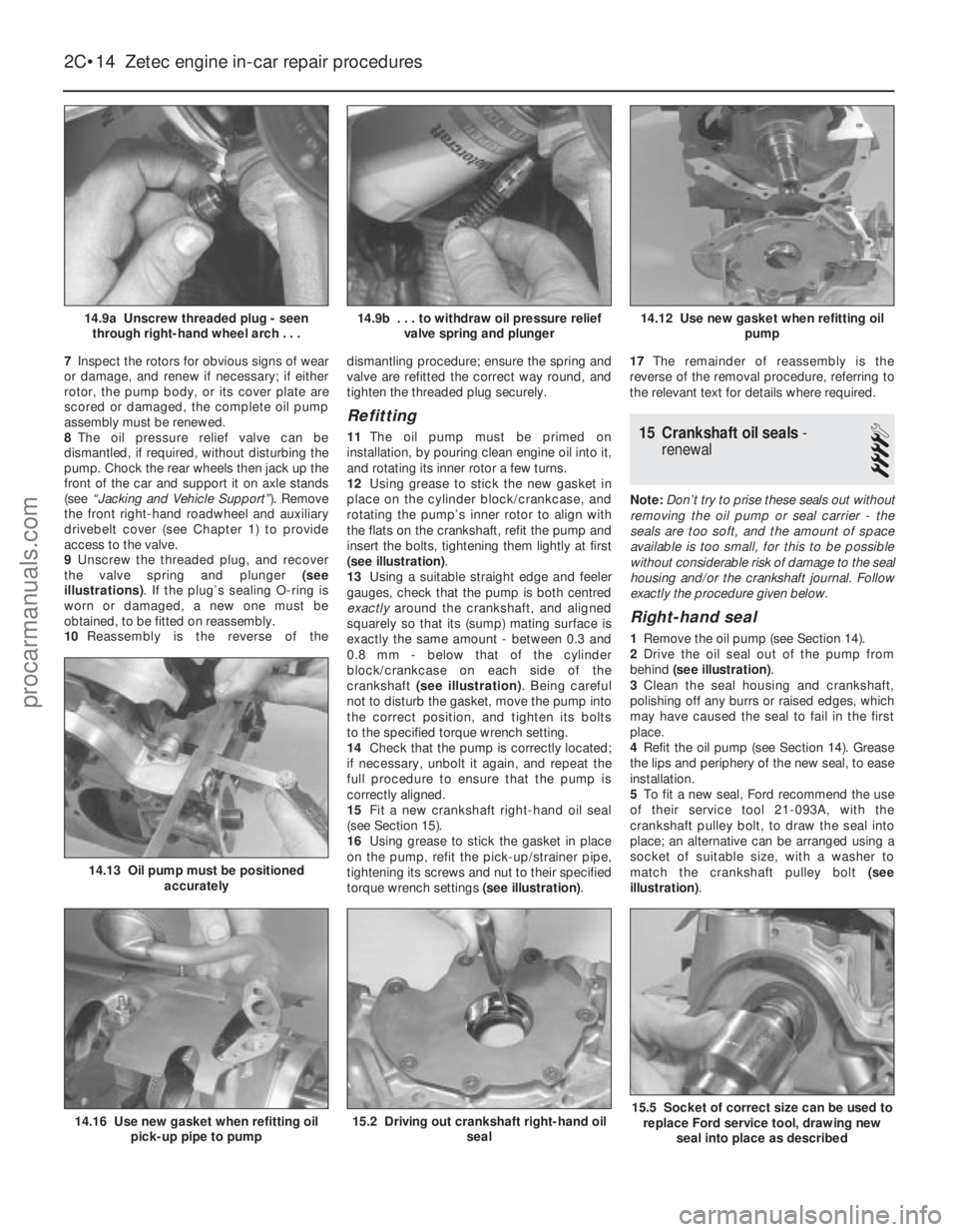
illustrations) . If the plug’s sealing O-ring is
worn or damaged, a new one must be
obtained, to be fitted on reassembly.
10 Reassembly is the reverse of the dismantling procedure; ensure the spring and
valve are refitted the correct way round, and
tighten the threaded plug securely.
Refitting
11
The oil pump must be primed on
installation, by pouring clean engine oil into it,
and rotating its inner rotor a few turns.
12 Using grease to stick the new gasket in
place on the cylinder block/crankcase, and
rotating the pump’s inner rotor to align with
the flats on the crankshaft, refit the pump and
insert the bolts, tightening them lightly at first
(see illustration) .
13 Using a suitable straight edge and feeler
gauges, check that the pump is both centred
exactly around the crankshaft, and aligned
squarely so that its (sump) mating surface is
exactly the same amount - between 0.3 and
0.8 mm - below that of the cylinder
block/crankcase on each side of the
crankshaft (see illustration) . Being careful
not to disturb the gasket, move the pump into
the correct position, and tighten its bolts
to the specified torque wrench setting.
14 Check that the pump is correctly located;
if necessary, unbolt it again, and repeat the
full procedure to ensure that the pump is
correctly aligned.
15 Fit a new crankshaft right-hand oil seal
(see Section 15).
16 Using grease to stick the gasket in place
on the pump, refit the pick-up/strainer pipe,
tightening its screws and nut to their specified
torque wrench settings (see illustration).17
The remainder of reassembly is the
reverse of the removal procedure, referring to
the relevant text for details where required.15 Crankshaft oil seals -
renewal
4
Note: Don’t try to prise these seals out without
removing the oil pump or seal carrier - the
seals are too soft, and the amount of space
available is too small, for this to be possible
without considerable risk of damage to the seal
housing and/or the crankshaft journal. Follow
exactly the procedure given below.
Right-hand seal
1 Remove the oil pump (see Section 14).
2 Drive the oil seal out of the pump from
behind (see illustration) .
3 Clean the seal housing and crankshaft,
polishing off any burrs or raised edges, which
may have caused the seal to fail in the first
place.
4 Refit the oil pump (see Section 14). Grease
the lips and periphery of the new seal, to ease
installation.
5 To fit a new seal, Ford recommend the use
of their service tool 21-093A, with the
crankshaft pulley bolt, to draw the seal into
place; an alternative can be arranged using a
socket of suitable size, with a washer to
match the crankshaft pulley bolt (see
illustration) .
2C•14Zetec engine in-car repair procedures
15.5 Socket of correct size can be used to
replace Ford service tool, drawing new
seal into place as described15.2 Driving out crankshaft right-hand oil seal14.16 Use new gasket when refitting oilpick-up pipe to pump
14.13 Oil pump must be positioned accurately
14.12 Use new gasket when refitting oil pump14.9b . . . to withdraw oil pressure reliefvalve spring and plunger14.9a Unscrew threaded plug - seenthrough right-hand wheel arch . . .
1595Ford Fiesta Remakeprocarmanuals.com
http://vnx.su
Page 68 of 296
6If such tools are not available, press the
seal squarely into place by hand; tap it in until
it is flush with the pump housing, using a soft-
faced mallet and a socket with an outside
diameter only slightly smaller than the seal’s
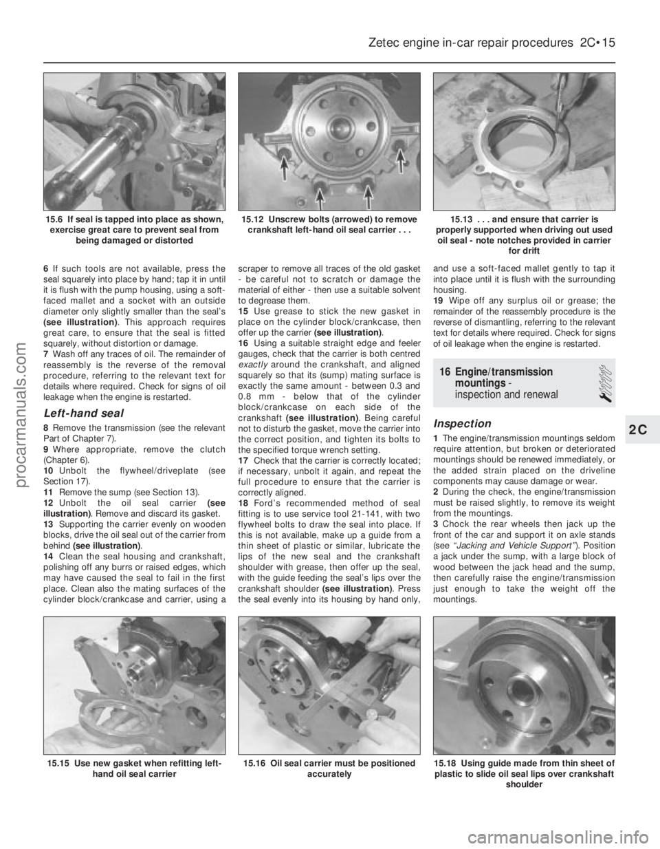
(see illustration) . This approach requires
great care, to ensure that the seal is fitted
squarely, without distortion or damage.
7 Wash off any traces of oil. The remainder of
reassembly is the reverse of the removal
procedure, referring to the relevant text for
details where required. Check for signs of oil
leakage when the engine is restarted.
Left-hand seal
8 Remove the transmission (see the relevant
Part of Chapter 7).
9 Where appropriate, remove the clutch
(Chapter 6).
10 Unbolt the flywheel/driveplate (see
Section 17).
11 Remove the sump (see Section 13).
12 Unbolt the oil seal carrier (see
illustration) . Remove and discard its gasket.
13 Supporting the carrier evenly on wooden
blocks, drive the oil seal out of the carrier from
behind (see illustration) .
14 Clean the seal housing and crankshaft,
polishing off any burrs or raised edges, which
may have caused the seal to fail in the first
place. Clean also the mating surfaces of the
cylinder block/crankcase and carrier, using a scraper to remove all traces of the old gasket
- be careful not to scratch or damage the
material of either - then use a suitable solvent
to degrease them.
15
Use grease to stick the new gasket in
place on the cylinder block/crankcase, then
offer up the carrier (see illustration).
16 Using a suitable straight edge and feeler
gauges, check that the carrier is both centred
exactly around the crankshaft, and aligned
squarely so that its (sump) mating surface is
exactly the same amount - between 0.3 and
0.8 mm - below that of the cylinder
block/crankcase on each side of the
crankshaft (see illustration) . Being careful
not to disturb the gasket, move the carrier into
the correct position, and tighten its bolts to
the specified torque wrench setting.
17 Check that the carrier is correctly located;
if necessary, unbolt it again, and repeat the
full procedure to ensure that the carrier is
correctly aligned.
18 Ford’s recommended method of seal
fitting is to use service tool 21-141, with two
flywheel bolts to draw the seal into place. If
this is not available, make up a guide from a
thin sheet of plastic or similar, lubricate the
lips of the new seal and the crankshaft
shoulder with grease, then offer up the seal,
with the guide feeding the seal’s lips over the
crankshaft shoulder (see illustration) . Press
the seal evenly into its housing by hand only, and use a soft-faced mallet gently to tap it
into place until it is flush with the surrounding
housing.
19
Wipe off any surplus oil or grease; the
remainder of the reassembly procedure is the
reverse of dismantling, referring to the relevant
text for details where required. Check for signs
of oil leakage when the engine is restarted.
16 Engine/transmission mountings -
inspection and renewal
1
Inspection
1 The engine/transmission mountings seldom
require attention, but broken or deteriorated
mountings should be renewed immediately, or
the added strain placed on the driveline
components may cause damage or wear.
2 During the check, the engine/transmission
must be raised slightly, to remove its weight
from the mountings.
3 Chock the rear wheels then jack up the
front of the car and support it on axle stands
(see “Jacking and Vehicle Support” ). Position
a jack under the sump, with a large block of
wood between the jack head and the sump,
then carefully raise the engine/transmission
just enough to take the weight off the
mountings.
Zetec engine in-car repair procedures 2C•15
15.13 . . . and ensure that carrier is
properly supported when driving out used oil seal - note notches provided in carrier for drift15.12 Unscrew bolts (arrowed) to removecrankshaft left-hand oil seal carrier . . .15.6 If seal is tapped into place as shown,exercise great care to prevent seal from being damaged or distorted
15.18 Using guide made from thin sheet ofplastic to slide oil seal lips over crankshaft
shoulder15.16 Oil seal carrier must be positionedaccurately15.15 Use new gasket when refitting left-hand oil seal carrier
2C
1595Ford Fiesta Remakeprocarmanuals.com
http://vnx.su
Page 76 of 296
3Referring to Chapter 1 for details, drain the
coolant and engine oil. Refit the drain plug to
the sump on completion.
4 Remove the bonnet as described in
Chapter 11.
5 Remove the air cleaner assembly as
described in the relevant Part of Chapter 4.
6 Release the retaining clips and detach the following coolant hoses. Allow for coolant
spillage as the hoses are detached
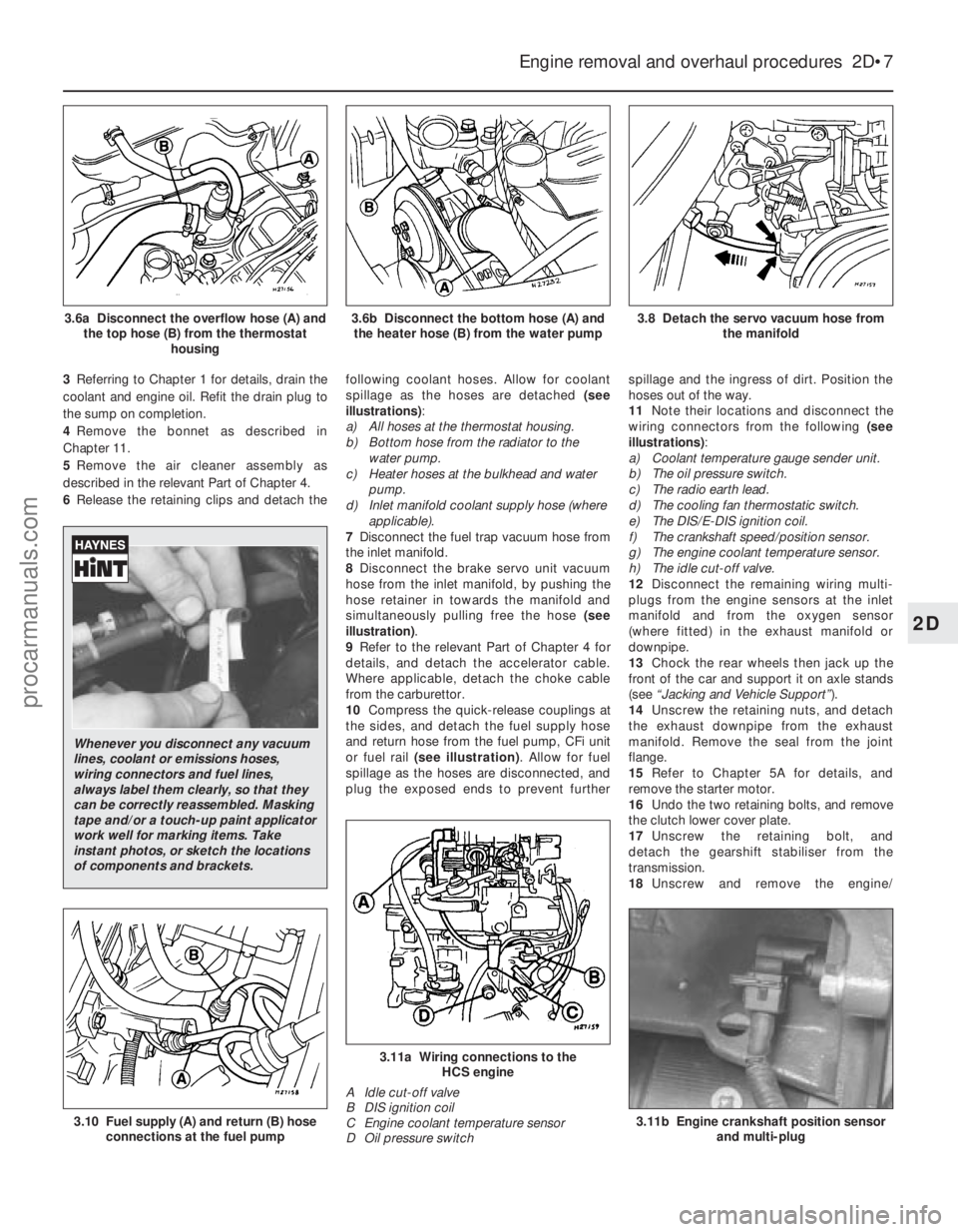
(see
illustrations) :
a) All hoses at the thermostat housing.
b) Bottom hose from the radiator to the
water pump.
c) Heater hoses at the bulkhead and water
pump.
d) Inlet manifold coolant supply hose (where
applicable).
7 Disconnect the fuel trap vacuum hose from
the inlet manifold.
8 Disconnect the brake servo unit vacuum
hose from the inlet manifold, by pushing the
hose retainer in towards the manifold and
simultaneously pulling free the hose (see
illustration) .
9 Refer to the relevant Part of Chapter 4 for
details, and detach the accelerator cable.
Where applicable, detach the choke cable
from the carburettor.
10 Compress the quick-release couplings at
the sides, and detach the fuel supply hose
and return hose from the fuel pump, CFi unit
or fuel rail (see illustration) . Allow for fuel
spillage as the hoses are disconnected, and
plug the exposed ends to prevent further spillage and the ingress of dirt. Position the
hoses out of the way.
11
Note their locations and disconnect the
wiring connectors from the following (see
illustrations) :
a) Coolant temperature gauge sender unit.
b) The oil pressure switch.
c) The radio earth lead.
d) The cooling fan thermostatic switch.
e) The DIS/E-DIS ignition coil.
f) The crankshaft speed/position sensor.
g) The engine coolant temperature sensor.
h) The idle cut-off valve.
12 Disconnect the remaining wiring multi-
plugs from the engine sensors at the inlet
manifold and from the oxygen sensor
(where fitted) in the exhaust manifold or
downpipe.
13 Chock the rear wheels then jack up the
front of the car and support it on axle stands
(see “Jacking and Vehicle Support” ).
14 Unscrew the retaining nuts, and detach
the exhaust downpipe from the exhaust
manifold. Remove the seal from the joint
flange.
15 Refer to Chapter 5A for details, and
remove the starter motor.
16 Undo the two retaining bolts, and remove
the clutch lower cover plate.
17 Unscrew the retaining bolt, and
detach the gearshift stabiliser from the
transmission.
18 Unscrew and remove the engine/
Engine removal and overhaul procedures 2D•7
3.8 Detach the servo vacuum hose from
the manifold3.6b Disconnect the bottom hose (A) andthe heater hose (B) from the water pump3.6a Disconnect the overflow hose (A) and the top hose (B) from the thermostat housing
3.11b Engine crankshaft position sensorand multi-plug
3.11a Wiring connections to the HCS engine
A Idle cut-off valve
B DIS ignition coil
C Engine coolant temperature sensor
D Oil pressure switch
3.10 Fuel supply (A) and return (B) hose connections at the fuel pump
2D
1595Ford Fiesta Remake
Whenever you disconnect any vacuum
lines, coolant or emissions hoses,
wiring connectors and fuel lines,
always label them clearly, so that they
can be correctly reassembled. Masking
tape and/or a touch-up paint applicator
work well for marking items. Take
instant photos, or sketch the locations
of components and brackets.
procarmanuals.com
http://vnx.su
Page 78 of 296
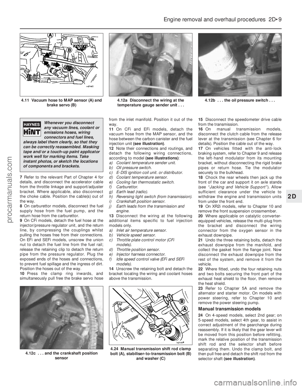
7Refer to the relevant Part of Chapter 4 for
details, and disconnect the accelerator cable
from the throttle linkage and support/adjuster
bracket. Where applicable, also disconnect
the choke cable. Position the cable(s) out of
the way.
8 On carburettor models, disconnect the fuel
supply hose from the fuel pump, and the
return hose from the carburettor.
9 On CFi models, detach the fuel hose at the
injector/pressure regulator unit, and the return
line, by compressing the couplings whilst
pulling the hoses free from their connections.
On EFi and SEFi models, unscrew the union
nut to detach the fuel line from the fuel rail;
release the retaining clip to detach the return
pipe from the pressure regulator. Plug the
exposed ends of the hoses and connections,
to prevent fuel spillage and the ingress of dirt.
Position the hoses out of the way.
10 Press the clamp ring inwards, and
simultaneously pull free the brake servo hose from the inlet manifold. Position it out of the
way.
11
On CFi and EFi models, detach the
vacuum hose from the MAP sensor, and the
hose between the carbon canister and the fuel
injection unit (see illustration) .
12 Note their connections and routings, and
detach the following wiring connections,
according to model (see illustrations):
a) Coolant temperature sender unit.
b) Oil pressure switch.
c) E-DIS ignition coil unit. or distributor.
d) Coolant temperature sensor.
e) Cooling fan thermostatic switch.
f) Carburettor.
g) Earth lead (radio).
h) Reversing light switch (from transmission).
i) Crankshaft position sensor.
j) Earth leads from the transmission and engine.
13 Disconnect the wiring at the following
additional items specific to fuel injection
models only.
a) Inlet air temperature sensor.
b) Vehicle speed sensor.
c) Throttle plate control motor (CFi models).
d) Throttle position sensor.
e) Injector harness connector.
f) Idle speed control valve (EFi and SEFi models).
14 Unscrew the retaining bolt and detach the
bracket locating the wiring and coolant hoses
above the transmission. 15
Disconnect the speedometer drive cable
from the transmission.
16 On manual transmission models,
disconnect the clutch cable from the release
lever at the transmission (see Chapter 6 for
details). Position the cable out of the way.
17 On vehicles fitted with the anti-lock
braking system, refer to Chapter 9 and release
the left-hand modulator from its mounting
bracket, without disconnecting the rigid brake
pipes or return hose. Tie the modulator
securely to the bulkhead.
18 Chock the rear wheels then jack up the
front of the car and support it on axle stands
(see “Jacking and Vehicle Support” ). Allow
sufficient clearance under the vehicle to
withdraw the engine and transmission units
from under the front end.
19 On XR2i models, refer to Chapter 10 and
remove the front suspension crossmember.
20 Where applicable on catalytic converter-
equipped vehicles, release the multi-plug from
the bracket and disconnect the wiring
connector from the oxygen sensor in the
exhaust downpipe.
21 Undo the three retaining bolts, detach the
exhaust downpipe from the manifold, and
collect the gasket from the flange joint. Now
disconnect the exhaust downpipe from the
rest of the system, and remove it from the
vehicle.
22 Where fitted, undo the four retaining nuts
and two bolts securing the front part of the
exhaust heat shield to the floor, then remove
the heat shield.
23 Refer to Chapter 5A and remove the
alternator and starter motor. On models with
power steering, refer to Chapter 10 and
remove the power steering pump.
Manual transmission models
24 On 4-speed models, select 2nd gear; on
5-speed models, select 4th gear, to assist in
correct adjustment of the gearchange during
reassembly. If it is likely that the gear lever will
be moved from this position before refitting,
mark the relative position of the transmission
shift rod and the selector shaft before
separating them. Undo the clamp bolt, and
then pull free and detach the shift rod from the
selector shaft (see illustration) .
Engine removal and overhaul procedures 2D•9
4.12b . . . the oil pressure switch . . .4.12a Disconnect the wiring at the
temperature gauge sender unit . . .4.11 Vacuum hose to MAP sensor (A) and brake servo (B)
4.24 Manual transmission shift rod clamp
bolt (A), stabiliser-to-transmission bolt (B)
and washer (C)4.12c . . . and the crankshaft position sensor
2D
1595Ford Fiesta Remake
Whenever you disconnect
any vacuum lines, coolant or
emissions hoses, wiring
connectors and fuel lines,
always label them clearly, so that they
can be correctly reassembled. Masking
tape and/or a touch-up paint applicator
work well for marking items. Take
instant photos, or sketch the locations
of components and brackets.
procarmanuals.com
http://vnx.su
Page 80 of 296
8Disconnect the accelerator cable from the
throttle linkage as described in Chapter 4D.
Secure the cable clear of the
engine/transmission.
9 Releasing its wire clip, unplug the wiring
connector from the power steering pressure
switch (where fitted), then disconnect the
earth cable from the engine lifting eye. Refit
the bolt after disconnecting the cable.
10 Marking or labelling all components as
they are disconnected, disconnect the
vacuum hoses as follows:
a) From the rear of the inlet manifold.
b) The braking system vacuum servo unit
hose - from the inlet manifold (see
Chapter 9 for details).
c) While you are there, trace the vacuum line
from the pulse-air filter housing, and
disconnect it from the pulse-air solenoid
valve.
d) Secure all these hoses so that they won’t
get damaged as the engine/transmission
is removed.
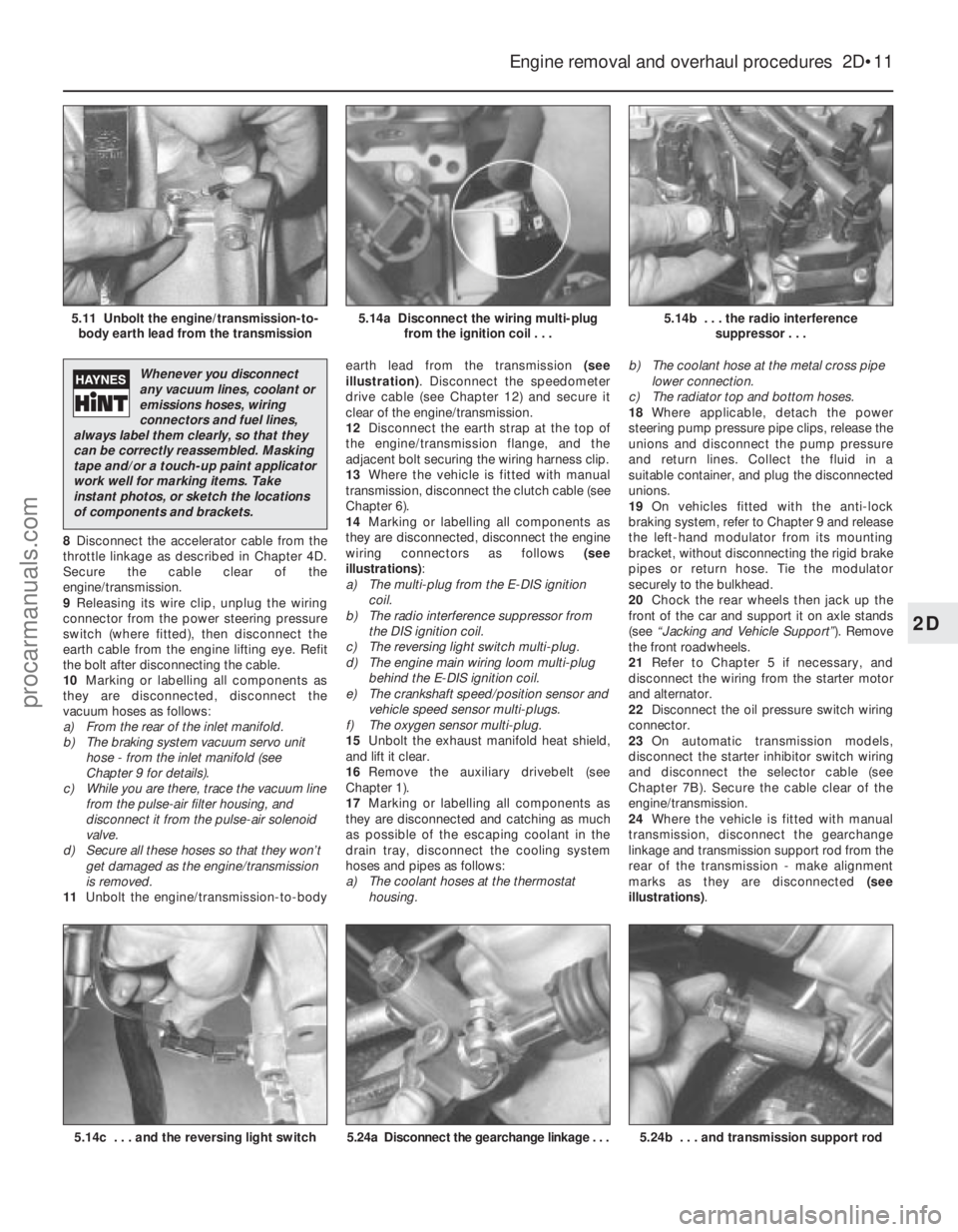
11 Unbolt the engine/transmission-to-body earth lead from the transmission
(see
illustration) . Disconnect the speedometer
drive cable (see Chapter 12) and secure it
clear of the engine/transmission.
12 Disconnect the earth strap at the top of
the engine/transmission flange, and the
adjacent bolt securing the wiring harness clip.
13 Where the vehicle is fitted with manual
transmission, disconnect the clutch cable (see
Chapter 6).
14 Marking or labelling all components as
they are disconnected, disconnect the engine
wiring connectors as follows (see
illustrations) :
a) The multi-plug from the E-DIS ignition
coil.
b) The radio interference suppressor from
the DIS ignition coil.
c) The reversing light switch multi-plug.
d) The engine main wiring loom multi-plug
behind the E-DIS ignition coil.
e) The crankshaft speed/position sensor and vehicle speed sensor multi-plugs.
f) The oxygen sensor multi-plug.
15 Unbolt the exhaust manifold heat shield,
and lift it clear.
16 Remove the auxiliary drivebelt (see
Chapter 1).
17 Marking or labelling all components as
they are disconnected and catching as much
as possible of the escaping coolant in the
drain tray, disconnect the cooling system
hoses and pipes as follows:
a) The coolant hoses at the thermostat housing. b)
The coolant hose at the metal cross pipe
lower connection.
c) The radiator top and bottom hoses.
18 Where applicable, detach the power
steering pump pressure pipe clips, release the
unions and disconnect the pump pressure
and return lines. Collect the fluid in a
suitable container, and plug the disconnected
unions.
19 On vehicles fitted with the anti-lock
braking system, refer to Chapter 9 and release
the left-hand modulator from its mounting
bracket, without disconnecting the rigid brake
pipes or return hose. Tie the modulator
securely to the bulkhead.
20 Chock the rear wheels then jack up the
front of the car and support it on axle stands
(see “Jacking and Vehicle Support” ). Remove
the front roadwheels.
21 Refer to Chapter 5 if necessary, and
disconnect the wiring from the starter motor
and alternator.
22 Disconnect the oil pressure switch wiring
connector.
23 On automatic transmission models,
disconnect the starter inhibitor switch wiring
and disconnect the selector cable (see
Chapter 7B). Secure the cable clear of the
engine/transmission.
24 Where the vehicle is fitted with manual
transmission, disconnect the gearchange
linkage and transmission support rod from the
rear of the transmission - make alignment
marks as they are disconnected (see
illustrations) .
Engine removal and overhaul procedures 2D•11
5.14b . . . the radio interference
suppressor . . .5.14a Disconnect the wiring multi-plugfrom the ignition coil . . .5.11 Unbolt the engine/transmission-to-body earth lead from the transmission
5.24b . . . and transmission support rod5.24a Disconnect the gearchange linkage . . .5.14c . . . and the reversing light switch
2D
1595Ford Fiesta Remake
Whenever you disconnect
any vacuum lines, coolant or
emissions hoses, wiring
connectors and fuel lines,
always label them clearly, so that they
can be correctly reassembled. Masking
tape and/or a touch-up paint applicator
work well for marking items. Take
instant photos, or sketch the locations
of components and brackets.
procarmanuals.com
http://vnx.su
Page 110 of 296
position at the carburettor, then secure the
outer cable with its retaining clip.
Adjustment
12To check that the choke cable is correctly
adjusted, the control knob must be pulled out
to the full-on position and the choke lever
must be in contact with its stop. Adjust as
required if necessary.
13 Press the choke knob fully in (to the off
position), then check that the choke linkage at
the carburettor has fully returned to its off
position and the choke valve plate in the
carburettor is at a right angle (90º) to the
venturi.
14 Refit the air cleaner.
15 Reconnect the battery, turn the ignition
on, operate the choke and check that the
choke warning light operates correctly.
7 Fuel pump -
testing, removal and refitting
2
Note: Refer to the warning note in Section 1
before proceeding.
Testing
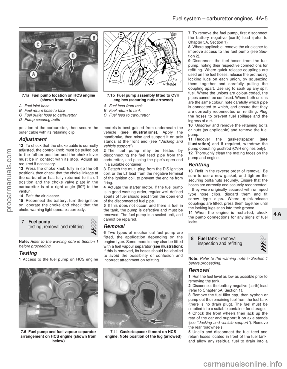
1 Access to the fuel pump on HCS engine models is best gained from underneath the
vehicle
(see illustrations) . Apply the
handbrake, then raise and support it on axle
stands at the front end (see “Jacking and
vehicle support” ).
2 The fuel pump may be tested by
disconnecting the fuel feed pipe from the
carburettor, and placing the pipe’s open end
in a suitable container.
3 Detach the multi-plug from the DIS ignition
coil, or the LT lead from the negative terminal
of the ignition coil, to prevent the engine from
firing.
4 Actuate the starter motor. If the fuel pump
is in good working order, regular well-defined
spurts of fuel should eject from the open end
of the disconnected fuel pipe.
5 If this does not occur, and there is fuel in
the tank, the pump is defective and must be
renewed. The fuel pump is a sealed unit, and
cannot be repaired.
Removal
6 Two types of mechanical fuel pump are
fitted, the application depending on the
engine type. Some models may also be fitted
with a fuel vapour separator (see illustration) ;
if this is removed, its hoses should be labelled
to avoid the possibility of confusion and
incorrect attachment on refitting. 7
To remove the fuel pump, first disconnect
the battery negative (earth) lead (refer to
Chapter 5A, Section 1).
8 Where applicable, remove the air cleaner to
improve access to the fuel pump (see Sec-
tion 2).
9 Disconnect the fuel hoses from the fuel
pump, noting their respective connections for
refitting. Where quick-release couplings are
used on the fuel hoses, release the protruding
locking lugs on each union, by squeezing
them together and carefully pulling the
coupling apart. Use rag to soak up any spilt
fuel. Where the unions are colour-coded, the
pipes cannot be confused. Where both unions
are the same colour, note carefully which pipe
is connected to which, and ensure that they
are correctly reconnected on refitting. Plug
the hoses to prevent fuel spillage and the
ingress of dirt.
10 Unscrew and remove the retaining bolts
or nuts (as applicable) and remove the fuel
pump.
11 Recover the gasket/spacer (see
illustration) and if required, withdraw the
pump operating pushrod (CVH engines only).
12 Thoroughly clean the mating faces on the
pump and engine.
Refitting
13 Refit in the reverse order of removal. Be
sure to use a new gasket, and tighten the
securing bolts/nuts securely. Ensure that the
hoses are correctly and securely reconnected.
If they were originally secured with crimped
type hose clips, discard them and fit
screw type clips. Where quick-release
couplings are fitted, press them together until
the locking lugs snap into their groove.
14 When the engine is restarted, check
the pump connections for any signs of fuel
leaks.
8 Fuel tank - removal,
inspection and refitting
3
Note: Refer to the warning note in Section 1
before proceeding.
Removal
1 Run the fuel level as low as possible prior to
removing the tank.
2 Disconnect the battery negative (earth) lead
(refer to Chapter 5A, Section 1).
3 Remove the fuel filler cap, then syphon or
pump out the remaining fuel from the fuel tank
(there is no drain plug). The fuel must be
emptied into a suitable container for storage.
4 Chock the front wheels then jack up the
rear of the car and support it on axle stands
(see “Jacking and vehicle support” ). Remove
the rear roadwheels.
5 Unclip and disconnect the fuel feed and
return hoses located in front of the fuel tank,
and allow any residual fuel to drain into a
Fuel system – carburettor engines 4A•5
7.6 Fuel pump and fuel vapour separator
arrangement on HCS engine (shown from
below)
7.1b Fuel pump assembly fitted to CVHengines (securing nuts arrowed)
A Fuel feed from tank
B Fuel return to tank
C Fuel feed to carburettor7.1a Fuel pump location on HCS engine (shown from below)
A Fuel inlet hose
B Fuel return hose to tank
C Fuel outlet hose to carburettor
D Pump securing bolts
7.11 Gasket/spacer fitment on HCS
engine. Note position of the lug (arrowed)
4A
1595Ford Fiesta Remakeprocarmanuals.com
http://vnx.su
Page 111 of 296
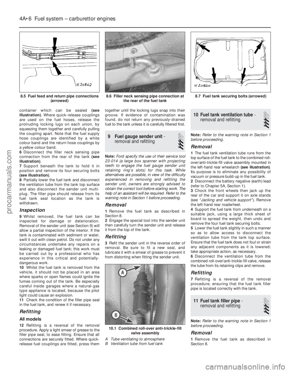
container which can be sealed (see
illustration) . Where quick-release couplings
are used on the fuel hoses, release the
protruding locking lugs on each union, by
squeezing them together and carefully pulling
the coupling apart. Note that the fuel supply
hose couplings are identified by a white
colour band and the return hose couplings by
a yellow colour band.
6 Disconnect the filler neck sensing pipe
connection from the rear of the tank (see
illustration) .
7 Support beneath the tank to hold it in
position and remove its four securing bolts
(see illustration) .
8 Partially lower the fuel tank and disconnect
the ventilation tube from the tank top surface
and also disconnect the sender unit multi-
plug. The filler pipe should release from its
fuel tank seal location as the tank is
withdrawn.
Inspection
9 Whilst removed, the fuel tank can be
inspected for damage or deterioration.
Removal of the sender unit (see Section 9) will
allow a partial inspection of the interior. If the
tank is contaminated with sediment or water,
swill it out with clean petrol. Do not under any
circumstances undertake any repairs on a
leaking or damaged fuel tank; this work must
be carried out by a professional who has
experience in this critical and potentially-
dangerous work.
10 Whilst the fuel tank is removed from the
vehicle, it should not be placed in an area
where sparks or open flames could ignite the
fumes coming out of the tank. Be especially
careful inside garages where a natural-gas
type appliance is located, because the pilot
light could cause an explosion.
11 Check the condition of the filler pipe seal
in the fuel tank, and renew it if necessary.
Refitting
All models
12 Refitting is a reversal of the removal
procedure. Apply a light smear of grease to the
filler pipe seal, to ease fitting. Ensure that all
connections are securely fitted. Where quick-
release fuel couplings are fitted, press them together until the locking lugs snap into their
groove. If evidence of contamination was
found, do not return any previously-drained
fuel to the tank unless it is carefully filtered first.
9
Fuel gauge sender unit -
removal and refitting
3
Note: Ford specify the use of their service tool
23-014 (a large box spanner with projecting
teeth to engage the fuel gauge sender unit
retaining ring’s slots) for this task. While
alternatives are possible, in view of the difficulty
experienced in removing and refitting the
sender unit, owners are strongly advised to
obtain the correct tool before starting work. The
help of an assistant will be required. Refer to the
warning note in Section 1 before proceeding.
Removal
1 Remove the fuel tank as described in
Section 8.
2 Engage the special tool into the sender unit
then carefully turn the sender unit and release
it from the top of the tank.
Refitting
3 Refit the sender unit in the reverse order of
removal. Be sure to fit a new seal, and
lubricate it with a smear of grease to prevent it
from distorting when fitting the sender unit.
10 Fuel tank ventilation tube -
removal and refitting
3
Note: Refer to the warning note in Section 1
before proceeding.
Removal
1 The fuel tank ventilation tube runs from the
top surface of the fuel tank to the combined roll-
over/anti-trickle-fill valve assembly mounted in
the left-hand rear wheelarch (see illustration).
Its purpose is to eliminate any possibility of
vacuum or pressure build-up in the fuel tank.
2 Disconnect the battery negative (earth) lead
(refer to Chapter 5A, Section 1).
3 Chock the front wheels then jack up the
rear of the car and support it on axle stands
(see “Jacking and vehicle support” ). Remove
the left-hand rear roadwheel.
4 Support the fuel tank from underneath on a
suitable jack, using a large thick sheet of
board to spread the weight, then undo and
remove the four fuel tank securing bolts.
5 Lower the fuel tank slightly in such a manner
so as to allow access to disconnect the
ventilation tube from the tank top surface.
Ensure that the fuel tank does not foul or strain
any adjacent components as it is lowered;
take appropriate action, as necessary.
6 Disconnect the ventilation tube from the
combined roll-over/anti-trickle-fill valve, release
the tube from its retaining clips and remove.
Refitting
7 Refitting is a reversal of the removal
procedure, ensuring that the fuel tank filler
pipe is located correctly with the tank.
11 Fuel tank filler pipe -
removal and refitting
3
Note: Refer to the warning note in Section 1
before proceeding.
Removal
1 Remove the fuel tank as described in
Section 8.
4A•6 Fuel system – carburettor engines
10.1 Combined roll-over anti-trickle-fill valve assembly
A Tube ventilating to atmosphere
B Ventilation tube from fuel tank
8.7 Fuel tank securing bolts (arrowed)8.6 Filler neck sensing pipe connection at the rear of the fuel tank
1595Ford Fiesta Remake
8.5 Fuel feed and return pipe connections
(arrowed)procarmanuals.com
http://vnx.su