1989 FORD FIESTA engine
[x] Cancel search: enginePage 236 of 296
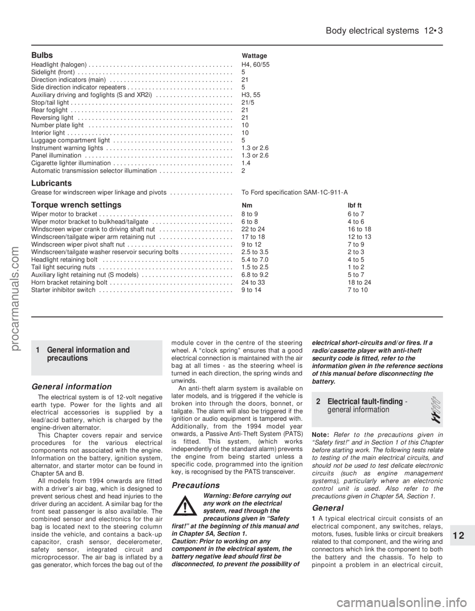
BulbsWattage
Headlight (halogen) . . . . . . . . . . . . . . . . . . . . . . . . . . . . . . . . . . . .\
. . . . . H4, 60/55
Sidelight (front) . . . . . . . . . . . . . . . . . . . . . . . . . . . . . . . . . . . .\
. . . . . . . . 5
Direction indicators (main) . . . . . . . . . . . . . . . . . . . . . . . . . . . . . . . . . . . 21
Side direction indicator repeaters . . . . . . . . . . . . . . . . . . . . . . . . . . . . . . 5
Auxiliary driving and foglights (S and XR2i) . . . . . . . . . . . . . . . . . . . . . . H3, 55
Stop/tail light . . . . . . . . . . . . . . . . . . . . . . . . . . . . . . . . . . . .\
. . . . . . . . . . 21/5
Rear foglight . . . . . . . . . . . . . . . . . . . . . . . . . . . . . . . . . . . .\
. . . . . . . . . . 21
Reversing light . . . . . . . . . . . . . . . . . . . . . . . . . . . . . . . . . . . .\
. . . . . . . . 21
Number plate light . . . . . . . . . . . . . . . . . . . . . . . . . . . . . . . . . . . .\
. . . . . 10
Interior light . . . . . . . . . . . . . . . . . . . . . . . . . . . . . . . . . . . .\
. . . . . . . . . . . 10
Luggage compartment light . . . . . . . . . . . . . . . . . . . . . . . . . . . . . . . . . . 5
Instrument warning lights . . . . . . . . . . . . . . . . . . . . . . . . . . . . . . . . . . . .\
1.3 or 2.6
Panel illumination . . . . . . . . . . . . . . . . . . . . . . . . . . . . . . . . . . . .\
. . . . . . 1.3 or 2.6
Cigarette lighter illumination . . . . . . . . . . . . . . . . . . . . . . . . . . . . . . . . . . 1.4
Automatic transmission selector illumination . . . . . . . . . . . . . . . . . . . . . 2
Lubricants
Grease for windscreen wiper linkage and pivots . . . . . . . . . . . . . . . . . . To Ford specification SAM-1C-911-A
Torque wrench settingsNm lbf ft
Wiper motor to bracket . . . . . . . . . . . . . . . . . . . . . . . . . . . . . . . . . . . .\
. . 8 to 9 6 to 7
Wiper motor bracket to bulkhead/tailgate . . . . . . . . . . . . . . . . . . . . . . . 6 to 8 4 to 6
Windscreen wiper crank to driving shaft nut . . . . . . . . . . . . . . . . . . . . . 22 to 24 16 to 18
Windscreen/tailgate wiper arm retaining nut . . . . . . . . . . . . . . . . . . . . . 17 to 18 12 to 13
Windscreen wiper pivot shaft nut . . . . . . . . . . . . . . . . . . . . . . . . . . . . . . 9 to 12 7 to 9
Windscreen/tailgate washer reservoir securing bolts . . . . . . . . . . . . . . . 2.5 to 3.5 2 to 3
Headlight retaining bolt . . . . . . . . . . . . . . . . . . . . . . . . . . . . . . . . . . . .\
. 5.4 to 7.0 4 to 5
Tail light securing nuts . . . . . . . . . . . . . . . . . . . . . . . . . . . . . . . . . . . .\
. . 1.5 to 2.5 1 to 2
Auxiliary light retaining nut (S models) . . . . . . . . . . . . . . . . . . . . . . . . . . 6.8 to 9.2 5 to 7
Horn bracket retaining bolt . . . . . . . . . . . . . . . . . . . . . . . . . . . . . . . . . . . 24 to 33 18 to 24
Starter inhibitor switch . . . . . . . . . . . . . . . . . . . . . . . . . . . . . . . . . . . .\
. . 9 to 14 7 to 10
Body electrical systems 12•3
12
1595Ford Fiesta Remake
1 General information and
precautions
General information
The electrical system is of 12-volt negative
earth type. Power for the lights and all
electrical accessories is supplied by a
lead/acid battery, which is charged by the
engine-driven alternator.
This Chapter covers repair and service
procedures for the various electrical
components not associated with the engine.
Information on the battery, ignition system,
alternator, and starter motor can be found in
Chapter 5A and B.
All models from 1994 onwards are fitted
with a driver’s air bag, which is designed to
prevent serious chest and head injuries to the
driver during an accident. A similar bag for the
front seat passenger is also available. The
combined sensor and electronics for the air
bag is located next to the steering column
inside the vehicle, and contains a back-up
capacitor, crash sensor, decelerometer,
safety sensor, integrated circuit and
microprocessor. The air bag is inflated by a
gas generator, which forces the bag out of the module cover in the centre of the steering
wheel. A “clock spring” ensures that a good
electrical connection is maintained with the air
bag at all times - as the steering wheel is
turned in each direction, the spring winds and
unwinds.
An anti-theft alarm system is available on
later models, and is triggered if the vehicle is
broken into through the doors, bonnet, or
tailgate. The alarm will also be triggered if the
ignition or audio equipment is tampered with.
Additionally, from the 1994 model year
onwards, a Passive Anti-Theft System (PATS)
is fitted. This system, (which works
independently of the standard alarm) prevents
the engine from being started unless a
specific code, programmed into the ignition
key, is recognised by the PATS transceiver.
Precautions
Warning: Before carrying out
any work on the electrical
system, read through the
precautions given in “Safety
first!” at the beginning of this manual and
in Chapter 5A, Section 1.
Caution: Prior to working on any
component in the electrical system, the
battery negative lead should first be
disconnected, to prevent the possibility of electrical short-circuits and/or fires. If a
radio/cassette player with anti-theft
security code is fitted, refer to the
information given in the reference sections
of this manual before disconnecting the
battery.
2 Electrical fault-finding
-
general information
2
Note: Refer to the precautions given in
“Safety first!” and in Section 1 of this Chapter
before starting work. The following tests relate
to testing of the main electrical circuits, and
should not be used to test delicate electronic
circuits (such as engine management
systems), particularly where an electronic
control unit is used. Also refer to the
precautions given in Chapter 5A, Section 1.
General
1 A typical electrical circuit consists of an
electrical component, any switches, relays,
motors, fuses, fusible links or circuit breakers
related to that component, and the wiring and
connectors which link the component to both
the battery and the chassis. To help to
pinpoint a problem in an electrical circuit,
procarmanuals.com
http://vnx.su
Page 237 of 296
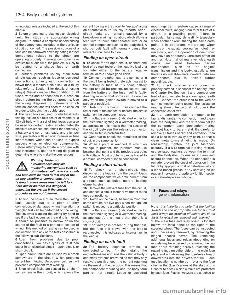
wiring diagrams are included at the end of this
manual.
2Before attempting to diagnose an electrical
fault, first study the appropriate wiring
diagram, to obtain a complete understanding
of the components included in the particular
circuit concerned. The possible sources of a
fault can be narrowed down by noting if other
components related to the circuit are
operating properly. If several components or
circuits fail at one time, the problem is likely to
be related to a shared fuse or earth
connection.
3 Electrical problems usually stem from
simple causes, such as loose or corroded
connections, a faulty earth connection, a
blown fuse, a melted fusible link, or a faulty
relay (refer to Section 3 for details of testing
relays). Visually inspect the condition of all
fuses, wires and connections in a problem
circuit before testing the components. Use
the wiring diagrams to determine which
terminal connections will need to be checked
in order to pinpoint the trouble-spot.
4 The basic tools required for electrical fault-
finding include a circuit tester or voltmeter (a
12-volt bulb with a set of test leads can also
be used for certain tests); an ohmmeter (to
measure resistance and check for continuity);
a battery and set of test leads; and a jumper
wire, preferably with a circuit breaker or fuse
incorporated, which can be used to bypass
suspect wires or electrical components.
Before attempting to locate a problem with
test instruments, use the wiring diagram to
determine where to make the connections.
Warning: Under no
circumstances may live
measuring instruments such as
ohmmeters, voltmeters or a bulb
and test leads be used to test any of the
air bag circuitry or components. Any
testing in these areas must be left to a
Ford dealer as there is a danger of
activating the system if the correct
procedures are not followed.
5 To find the source of an intermittent wiring
fault (usually due to a poor or dirty
connection, or damaged wiring insulation), a
“wiggle” test can be performed on the wiring.
This involves wiggling the wiring by hand to
see if the fault occurs as the wiring is moved.
It should be possible to narrow down the
source of the fault to a particular section of
wiring. This method of testing can be used in
conjunction with any of the tests described in
the following sub-Sections.
6 Apart from problems due to poor
connections, two basic types of fault can
occur in an electrical circuit - open-circuit, or
short-circuit.
7 Open-circuit faults are caused by a break
somewhere in the circuit, which prevents
current from flowing. An open-circuit fault will
prevent a component from working.
8 Short-circuit faults are caused by a “short”
somewhere in the circuit, which allows the current flowing in the circuit to “escape” along
an alternative route, usually to earth. Short-
circuit faults are normally caused by a
breakdown in wiring insulation, which allows a
feed wire to touch either another wire, or an
earthed component such as the bodyshell. A
short-circuit fault will normally cause the
relevant circuit fuse to blow.
Finding an open-circuit
9
To check for an open-circuit, connect one
lead of a circuit tester or the negative lead of a
voltmeter either to the battery negative
terminal or to a known good earth.
10 Connect the other lead to a connector in
the circuit being tested, preferably nearest to
the battery or fuse. At this point, battery
voltage should be present, unless the lead
from the battery or the fuse itself is faulty
(bearing in mind that some circuits are live
only when the ignition switch is moved to a
particular position).
11 Switch on the circuit, then connect the
tester lead to the connector nearest the circuit
switch on the component side.
12 If voltage is present (indicated either by
the tester bulb lighting or a voltmeter reading,
as applicable), this means that the section of
the circuit between the relevant connector
and the switch is problem-free.
13 Continue to check the remainder of the
circuit in the same fashion.
14 When a point is reached at which no
voltage is present, the problem must lie
between that point and the previous test point
with voltage. Most problems can be traced to
a broken, corroded or loose connection.
Finding a short-circuit
15 To check for a short-circuit, first
disconnect the load(s) from the circuit (loads
are the components which draw current from
a circuit, such as bulbs, motors, heating
elements, etc).
16 Remove the relevant fuse from the circuit,
and connect a circuit tester or voltmeter to the
fuse connections.
17 Switch on the circuit, bearing in mind that
some circuits are live only when the ignition
switch is moved to a particular position.
18 If voltage is present (indicated either by
the tester bulb lighting or a voltmeter reading,
as applicable), this means that there is a
short-circuit.
19 If no voltage is present during this test,
but the fuse still blows with the load(s)
reconnected, this indicates an internal fault in
the load(s).
Finding an earth fault
20 The battery negative terminal is
connected to “earth” - the metal of the
engine/transmission and the vehicle body -
and many systems are wired so that they only
receive a positive feed, the current returning
via the metal of the car body. This means that
the component mounting and the body form
part of that circuit. Loose or corroded mountings can therefore cause a range of
electrical faults, ranging from total failure of a
circuit, to a puzzling partial failure. In
particular, lights may shine dimly (especially
when another circuit sharing the same earth
point is in operation), motors (eg wiper
motors or the radiator cooling fan motor) may
run slowly, and the operation of one circuit
may have an apparently-unrelated effect on
another. Note that on many vehicles, earth
straps are used between certain
components, such as the engine/
transmission and the body, usually where
there is no metal-to-metal contact between
components, due to flexible rubber
mountings, etc.
21
To check whether a component is
properly earthed, disconnect the battery (refer
to Chapter 5A, Section 1) and connect one
lead of an ohmmeter to a known good earth
point. Connect the other lead to the wire or
earth connection being tested. The resistance
reading should be zero; if not, check the
connection as follows.
22 If an earth connection is thought to be
faulty, dismantle the connection, and clean
both the bodyshell and the wire terminal (or
the component earth connection mating
surface) back to bare metal. Be careful to
remove all traces of dirt and corrosion, then
use a knife to trim away any paint, so that a
clean metal-to-metal joint is made. On
reassembly, tighten the joint fasteners
securely; if a wire terminal is being refitted,
use serrated washers between the terminal
and the bodyshell, to ensure a clean and
secure connection. When the connection is
remade, prevent the onset of corrosion in the
future by applying a coat of petroleum jelly or
silicone-based grease, or by spraying on (at
regular intervals) a proprietary ignition sealer
or a water-dispersant lubricant.
3 Fuses and relays -
general information
Note: It is important to note that the ignition
switch and the appropriate electrical circuit
must always be switched off before any of the
fuses (or relays) are removed and renewed.
1 The main fuse and relay board is located
below the facia panel to the right of the
steering wheel. The fuses can be inspected
and if necessary renewed, by removing the
hinged access cover. The remaining
additional fuses and relays (depending on
model) may be accessed by removing the two
fuse board retaining screws, releasing the
retaining lugs on either side of the main fuse
plate and withdrawing the fuse/relay board
downwards into the driver’s footwell. Each
fuse location is numbered - refer to the fuse
chart in the Specifications at the start of this
Chapter to check which circuits are protected
by each fuse. Plastic tweezers are attached to
12•4 Body electrical systems
1595Ford Fiesta Remakeprocarmanuals.com
http://vnx.su
Page 239 of 296
windows (early models) and the tailgate
remote release mechanism, where fitted.
19Disconnect the battery negative (earth)
lead (refer to Chapter 5A, Section 1).
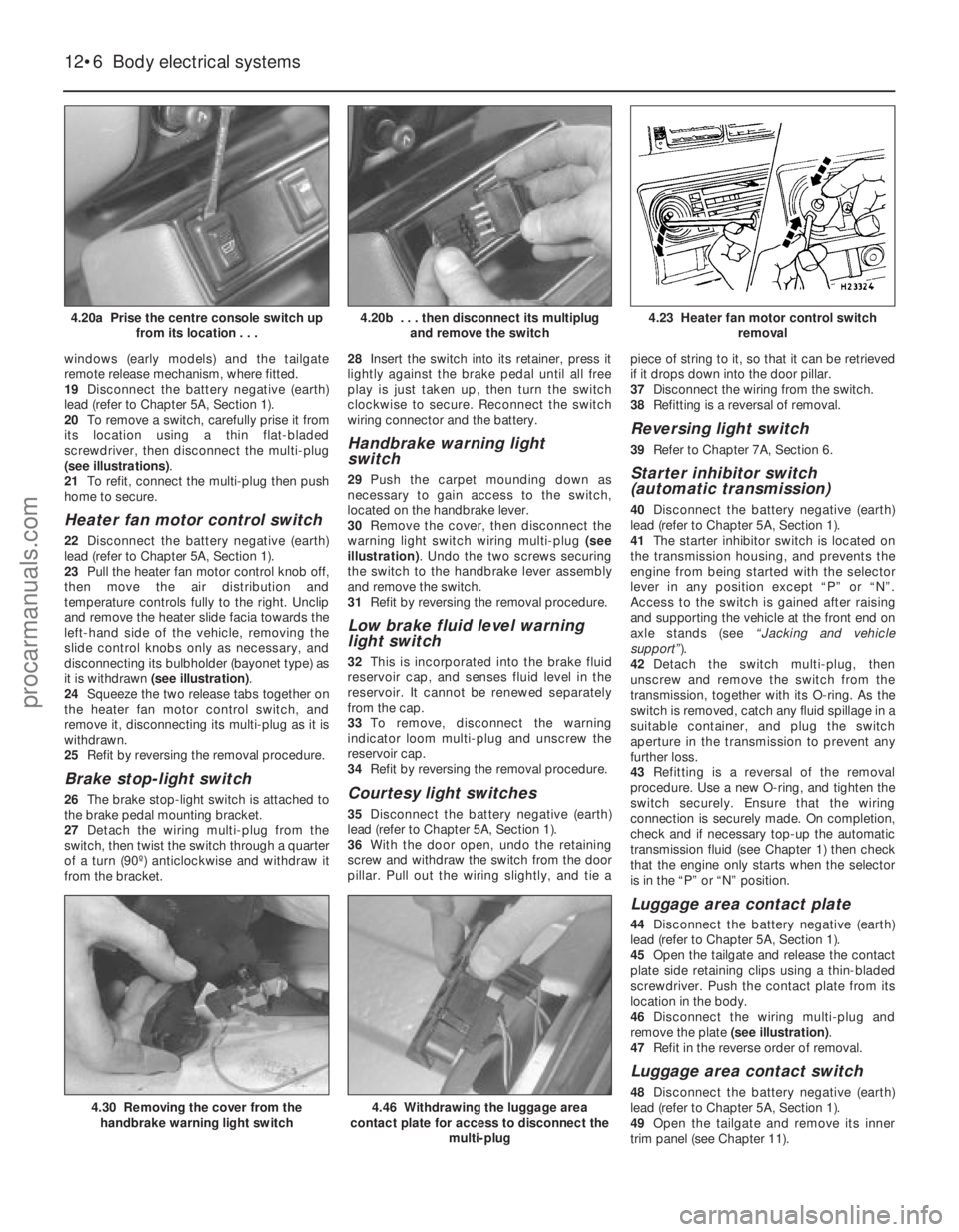
20 To remove a switch, carefully prise it from
its location using a thin flat-bladed
screwdriver, then disconnect the multi-plug
(see illustrations) .
21 To refit, connect the multi-plug then push
home to secure.
Heater fan motor control switch
22 Disconnect the battery negative (earth)
lead (refer to Chapter 5A, Section 1).
23 Pull the heater fan motor control knob off,
then move the air distribution and
temperature controls fully to the right. Unclip
and remove the heater slide facia towards the
left-hand side of the vehicle, removing the
slide control knobs only as necessary, and
disconnecting its bulbholder (bayonet type) as
it is withdrawn (see illustration) .
24 Squeeze the two release tabs together on
the heater fan motor control switch, and
remove it, disconnecting its multi-plug as it is
withdrawn.
25 Refit by reversing the removal procedure.
Brake stop-light switch
26The brake stop-light switch is attached to
the brake pedal mounting bracket.
27 Detach the wiring multi-plug from the
switch, then twist the switch through a quarter
of a turn (90º) anticlockwise and withdraw it
from the bracket. 28
Insert the switch into its retainer, press it
lightly against the brake pedal until all free
play is just taken up, then turn the switch
clockwise to secure. Reconnect the switch
wiring connector and the battery.
Handbrake warning light
switch
29 Push the carpet mounding down as
necessary to gain access to the switch,
located on the handbrake lever.
30 Remove the cover, then disconnect the
warning light switch wiring multi-plug (see
illustration) . Undo the two screws securing
the switch to the handbrake lever assembly
and remove the switch.
31 Refit by reversing the removal procedure.
Low brake fluid level warning
light switch
32This is incorporated into the brake fluid
reservoir cap, and senses fluid level in the
reservoir. It cannot be renewed separately
from the cap.
33 To remove, disconnect the warning
indicator loom multi-plug and unscrew the
reservoir cap.
34 Refit by reversing the removal procedure.
Courtesy light switches
35Disconnect the battery negative (earth)
lead (refer to Chapter 5A, Section 1).
36 With the door open, undo the retaining
screw and withdraw the switch from the door
pillar. Pull out the wiring slightly, and tie a piece of string to it, so that it can be retrieved
if it drops down into the door pillar.
37
Disconnect the wiring from the switch.
38 Refitting is a reversal of removal.
Reversing light switch
39Refer to Chapter 7A, Section 6.
Starter inhibitor switch
(automatic transmission)
40Disconnect the battery negative (earth)
lead (refer to Chapter 5A, Section 1).
41 The starter inhibitor switch is located on
the transmission housing, and prevents the
engine from being started with the selector
lever in any position except “P” or “N”.
Access to the switch is gained after raising
and supporting the vehicle at the front end on
axle stands (see “Jacking and vehicle
support” ).
42 Detach the switch multi-plug, then
unscrew and remove the switch from the
transmission, together with its O-ring. As the
switch is removed, catch any fluid spillage in a
suitable container, and plug the switch
aperture in the transmission to prevent any
further loss.
43 Refitting is a reversal of the removal
procedure. Use a new O-ring, and tighten the
switch securely. Ensure that the wiring
connection is securely made. On completion,
check and if necessary top-up the automatic
transmission fluid (see Chapter 1) then check
that the engine only starts when the selector
is in the “P” or “N” position.
Luggage area contact plate
44 Disconnect the battery negative (earth)
lead (refer to Chapter 5A, Section 1).
45 Open the tailgate and release the contact
plate side retaining clips using a thin-bladed
screwdriver. Push the contact plate from its
location in the body.
46 Disconnect the wiring multi-plug and
remove the plate (see illustration).
47 Refit in the reverse order of removal.
Luggage area contact switch
48Disconnect the battery negative (earth)
lead (refer to Chapter 5A, Section 1).
49 Open the tailgate and remove its inner
trim panel (see Chapter 11).
12•6 Body electrical systems
4.46 Withdrawing the luggage area
contact plate for access to disconnect the
multi-plug4.30 Removing the cover from thehandbrake warning light switch
4.23 Heater fan motor control switch removal4.20b . . . then disconnect its multiplugand remove the switch4.20a Prise the centre console switch up from its location . . .
1595Ford Fiesta Remakeprocarmanuals.com
http://vnx.su
Page 240 of 296
50Undo the two screws securing the contact
switch and withdraw it from its tailgate
location.
51 Unclip and disconnect the switch multi-
plug, and disconnect the earth wiring.
Remove the switch.
52 Refit in the reverse order of removal.
Make sure that the pins and their contacts are
clean. On completion, check the operation of
the rear wipers, courtesy light, heated rear
window and the tailgate release/central
locking system.
Electric window switches
(1992 models onward)
53 On later models the electric window
switches are located in the upper surfaces of
the door stowage pockets. Removal and
refitting is the same as for the earlier centre
console mounted switches described
previously in this Section.
5 Bulbs (exterior lights) -
renewal
1
Note: Ensure that all exterior lights are
switched off before disconnecting the wiring
connectors to any exterior light bulbs. Note
that if a bulb fails, and has just been in use, it
will still be extremely hot, particularly in the
case of a headlight bulb.
Headlight
1 From within the engine compartment,
disconnect the multi-plug from the back of the
headlight.
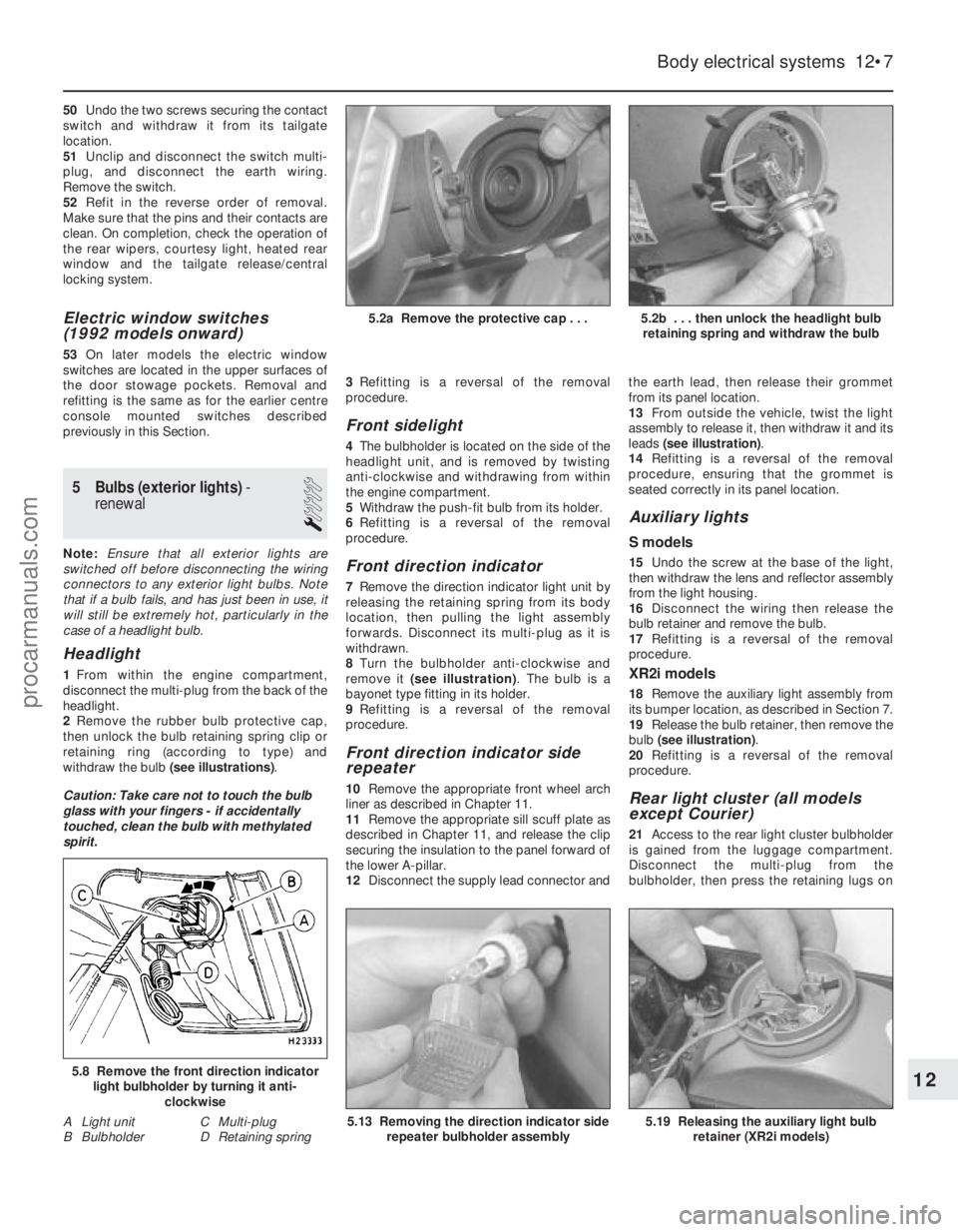
2 Remove the rubber bulb protective cap,
then unlock the bulb retaining spring clip or
retaining ring (according to type) and
withdraw the bulb (see illustrations).
Caution: Take care not to touch the bulb
glass with your fingers - if accidentally
touched, clean the bulb with methylated
spirit. 3
Refitting is a reversal of the removal
procedure.
Front sidelight
4 The bulbholder is located on the side of the
headlight unit, and is removed by twisting
anti-clockwise and withdrawing from within
the engine compartment.
5 Withdraw the push-fit bulb from its holder.
6 Refitting is a reversal of the removal
procedure.
Front direction indicator
7 Remove the direction indicator light unit by
releasing the retaining spring from its body
location, then pulling the light assembly
forwards. Disconnect its multi-plug as it is
withdrawn.
8 Turn the bulbholder anti-clockwise and
remove it (see illustration) . The bulb is a
bayonet type fitting in its holder.
9 Refitting is a reversal of the removal
procedure.
Front direction indicator side
repeater
10 Remove the appropriate front wheel arch
liner as described in Chapter 11.
11 Remove the appropriate sill scuff plate as
described in Chapter 11, and release the clip
securing the insulation to the panel forward of
the lower A-pillar.
12 Disconnect the supply lead connector and the earth lead, then release their grommet
from its panel location.
13
From outside the vehicle, twist the light
assembly to release it, then withdraw it and its
leads (see illustration) .
14 Refitting is a reversal of the removal
procedure, ensuring that the grommet is
seated correctly in its panel location.
Auxiliary lights
S models
15 Undo the screw at the base of the light,
then withdraw the lens and reflector assembly
from the light housing.
16 Disconnect the wiring then release the
bulb retainer and remove the bulb.
17 Refitting is a reversal of the removal
procedure.
XR2i models
18 Remove the auxiliary light assembly from
its bumper location, as described in Section 7.
19 Release the bulb retainer, then remove the
bulb (see illustration) .
20 Refitting is a reversal of the removal
procedure.
Rear light cluster (all models
except Courier)
21 Access to the rear light cluster bulbholder
is gained from the luggage compartment.
Disconnect the multi-plug from the
bulbholder, then press the retaining lugs on
Body electrical systems 12•7
5.2b . . . then unlock the headlight bulb retaining spring and withdraw the bulb5.2a Remove the protective cap . . .
5.19 Releasing the auxiliary light bulb retainer (XR2i models)5.13 Removing the direction indicator siderepeater bulbholder assembly
5.8 Remove the front direction indicatorlight bulbholder by turning it anti-
clockwise
A Light unit C Multi-plug
B Bulbholder D Retaining spring12
1595Ford Fiesta Remakeprocarmanuals.com
http://vnx.su
Page 245 of 296
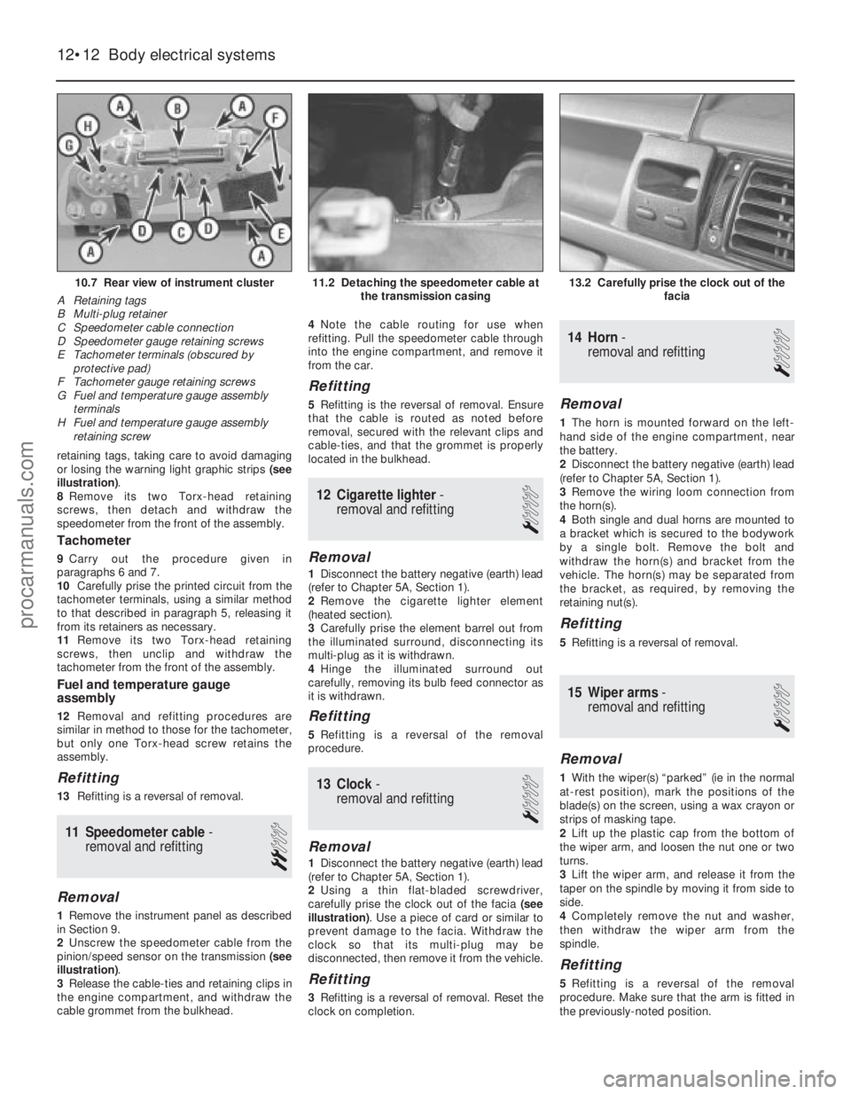
retaining tags, taking care to avoid damaging
or losing the warning light graphic strips (see
illustration) .
8 Remove its two Torx-head retaining
screws, then detach and withdraw the
speedometer from the front of the assembly.
Tachometer
9 Carry out the procedure given in
paragraphs 6 and 7.
10 Carefully prise the printed circuit from the
tachometer terminals, using a similar method
to that described in paragraph 5, releasing it
from its retainers as necessary.
11 Remove its two Torx-head retaining
screws, then unclip and withdraw the
tachometer from the front of the assembly.
Fuel and temperature gauge
assembly
12 Removal and refitting procedures are
similar in method to those for the tachometer,
but only one Torx-head screw retains the
assembly.
Refitting
13 Refitting is a reversal of removal.
11 Speedometer cable -
removal and refitting
2
Removal
1 Remove the instrument panel as described
in Section 9.
2 Unscrew the speedometer cable from the
pinion/speed sensor on the transmission (see
illustration) .
3 Release the cable-ties and retaining clips in
the engine compartment, and withdraw the
cable grommet from the bulkhead. 4
Note the cable routing for use when
refitting. Pull the speedometer cable through
into the engine compartment, and remove it
from the car.
Refitting
5 Refitting is the reversal of removal. Ensure
that the cable is routed as noted before
removal, secured with the relevant clips and
cable-ties, and that the grommet is properly
located in the bulkhead.
12 Cigarette lighter -
removal and refitting
1
Removal
1 Disconnect the battery negative (earth) lead
(refer to Chapter 5A, Section 1).
2 Remove the cigarette lighter element
(heated section).
3 Carefully prise the element barrel out from
the illuminated surround, disconnecting its
multi-plug as it is withdrawn.
4 Hinge the illuminated surround out
carefully, removing its bulb feed connector as
it is withdrawn.
Refitting
5 Refitting is a reversal of the removal
procedure.
13 Clock -
removal and refitting
1
Removal
1 Disconnect the battery negative (earth) lead
(refer to Chapter 5A, Section 1).
2 Using a thin flat-bladed screwdriver,
carefully prise the clock out of the facia (see
illustration) . Use a piece of card or similar to
prevent damage to the facia. Withdraw the
clock so that its multi-plug may be
disconnected, then remove it from the vehicle.
Refitting
3 Refitting is a reversal of removal. Reset the
clock on completion.
14 Horn -
removal and refitting
1
Removal
1 The horn is mounted forward on the left-
hand side of the engine compartment, near
the battery.
2 Disconnect the battery negative (earth) lead
(refer to Chapter 5A, Section 1).
3 Remove the wiring loom connection from
the horn(s).
4 Both single and dual horns are mounted to
a bracket which is secured to the bodywork
by a single bolt. Remove the bolt and
withdraw the horn(s) and bracket from the
vehicle. The horn(s) may be separated from
the bracket, as required, by removing the
retaining nut(s).
Refitting
5 Refitting is a reversal of removal.
15 Wiper arms -
removal and refitting
1
Removal
1 With the wiper(s) “parked” (ie in the normal
at-rest position), mark the positions of the
blade(s) on the screen, using a wax crayon or
strips of masking tape.
2 Lift up the plastic cap from the bottom of
the wiper arm, and loosen the nut one or two
turns.
3 Lift the wiper arm, and release it from the
taper on the spindle by moving it from side to
side.
4 Completely remove the nut and washer,
then withdraw the wiper arm from the
spindle.
Refitting
5 Refitting is a reversal of the removal
procedure. Make sure that the arm is fitted in
the previously-noted position.
12•12 Body electrical systems
13.2 Carefully prise the clock out of the facia11.2 Detaching the speedometer cable atthe transmission casing10.7 Rear view of instrument cluster
A Retaining tags
B Multi-plug retainer
C Speedometer cable connection
D Speedometer gauge retaining screws
E Tachometer terminals (obscured by protective pad)
F Tachometer gauge retaining screws
G Fuel and temperature gauge assembly
terminals
H Fuel and temperature gauge assembly retaining screw
1595Ford Fiesta Remakeprocarmanuals.com
http://vnx.su
Page 247 of 296
2Carry out the procedure detailed in Sec-
tion 16, paragraphs 2 to 6.
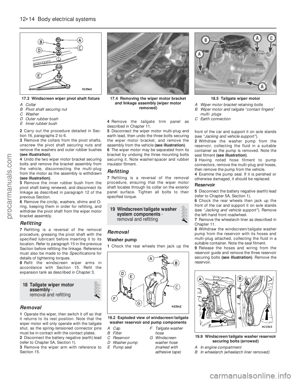
3 Remove the collars from the pivot shafts,
unscrew the pivot shaft securing nuts and
remove the washers and outer rubber bushes
(see illustration) .
4 Undo the two wiper motor bracket securing
bolts and remove the bracket assembly from
the vehicle, disconnecting the multi-plug
from the motor as the assembly is withdrawn
(see illustration) .
5 Remove the inner rubber bush from the
pivot shaft being renewed, and disconnect its
linkage as described in paragraph 12 of the
previous Section.
6 Remove the circlip, washers, shims and O-
ring, keeping them in order for refitting, and
withdraw the pivot shaft from the wiper motor
bracket assembly.
Refitting
7 Refitting is a reversal of the removal
procedure, greasing the pivot shaft with the
specified lubricant before inserting it to its
location. Refer to paragraph 15 in the previous
Section before refitting the linkage. Reference
must also be made to the Specificationsfor
details of tightening torques.
8 Refit the windscreen wiper arms in
accordance with Section 15. Refit the
expansion tank as described in Chapter 3.
18 Tailgate wiper motor assembly -
removal and refitting
1
Removal
1 Operate the wiper, then switch it off so that
it returns to its rest position. Note that the
wiper motor will only operate with the tailgate
shut, as the spring-tensioned connector pins
must be in contact with the contact plates.
2 Disconnect the battery negative (earth) lead
(refer to Chapter 5A, Section 1).
3 Remove the wiper arm with reference to
Section 15. 4
Remove the tailgate trim panel as
described in Chapter 11.
5 Disconnect the wiper motor multi-plug and
earth lead, then undo the three bolts securing
the wiper motor bracket, and remove the
assembly from the vehicle (see illustration).
6 The wiper motor may be separated from its
bracket by undoing the three mounting bolts
securing it. Note washer/spacer and rubber
insulator fitment.
Refitting
7 Refitting is a reversal of the removal
procedure, ensuring that the wiper motor
shaft locates through its collar on the exterior
panel surface. Tighten all bolts to their
specified torque.
19 Windscreen/tailgate washer system components -
removal and refitting
1
Removal
Washer pump
1 Chock the rear wheels then jack up the front of the car and support it on axle stands
(see
“Jacking and vehicle support” ).
2 Withdraw the washer pump from the
reservoir, collecting the fluid in a suitable
container as the pump is removed. Note the
seal fitment (see illustration) .
3 Having noted hose fitment to pump
connectors, remove the multi-plug and hoses,
then remove the pump from the vehicle.
4 Examine the pump seal. If it is perished or
otherwise damaged, it should be replaced.
Reservoir
5 Disconnect the battery negative (earth) lead
(refer to Chapter 5A, Section 1).
6 Chock the rear wheels then jack up the
front of the car and support it on axle stands
(see “Jacking and vehicle support” ). Remove
the left-hand front roadwheel.
7 Remove the wheelarch liner as described in
Chapter 11.
8 Withdraw the windscreen/tailgate washer
pump from the reservoir with its hoses and
multi-plug attached, collecting the fluid in a
suitable container. Note the seal fitment.
9 Release the hoses and wiring from the
reservoir guide and remove the three reservoir
securing bolts (see illustration) . Remove the
reservoir.
12•14 Body electrical systems
19.9 Windscreen/tailgate washer reservoir
securing bolts (arrowed)
A In engine compartment
B In wheelarch (wheelarch liner removed)
19.2 Exploded view of windscreen/tailgate washer reservoir and pump components
A Cap
B Filter
C Reservoir
D Washer pump
E Pump seal F Tailgate washer
hose
G Windscreen
washer hose
(marked with
adhesive tape)
18.5 Tailgate wiper motor
A Wiper motor bracket retaining bolts
B Wiper motor and tailgate “contact fingers” multi- plugs
C Earth connection17.4 Removing the wiper motor bracket and linkage assembly (wiper motor removed)17.3 Windscreen wiper pivot shaft fixture
A Collar
B Pivot shaft securing nut
C Washer
D Outer rubber bush
E Inner rubber bush
1595Ford Fiesta Remakeprocarmanuals.com
http://vnx.su
Page 248 of 296
Windscreen washer jets and hoses
10Disconnect the battery negative (earth)
lead (refer to Chapter 5A, Section 1).
11 With the bonnet raised and supported on
its stay, release the fasteners securing its
insulation panel (where fitted). Remove the
insulation panel.
12 Carefully press in the retaining lugs on the
washer jets using a flat-bladed screwdriver,
then raise the washer jets from the exterior
surface of the bonnet and separate them from
their hoses
13 The windscreen washer jet hose may have
been fitted with a one-way (non-return) valve.
If this is the case, the main hose run sections
can be removed from either side of the valve
as required.
14 Chock the rear wheels then jack up the
front of the car and support it on axle stands
(see “Jacking and vehicle support” ).
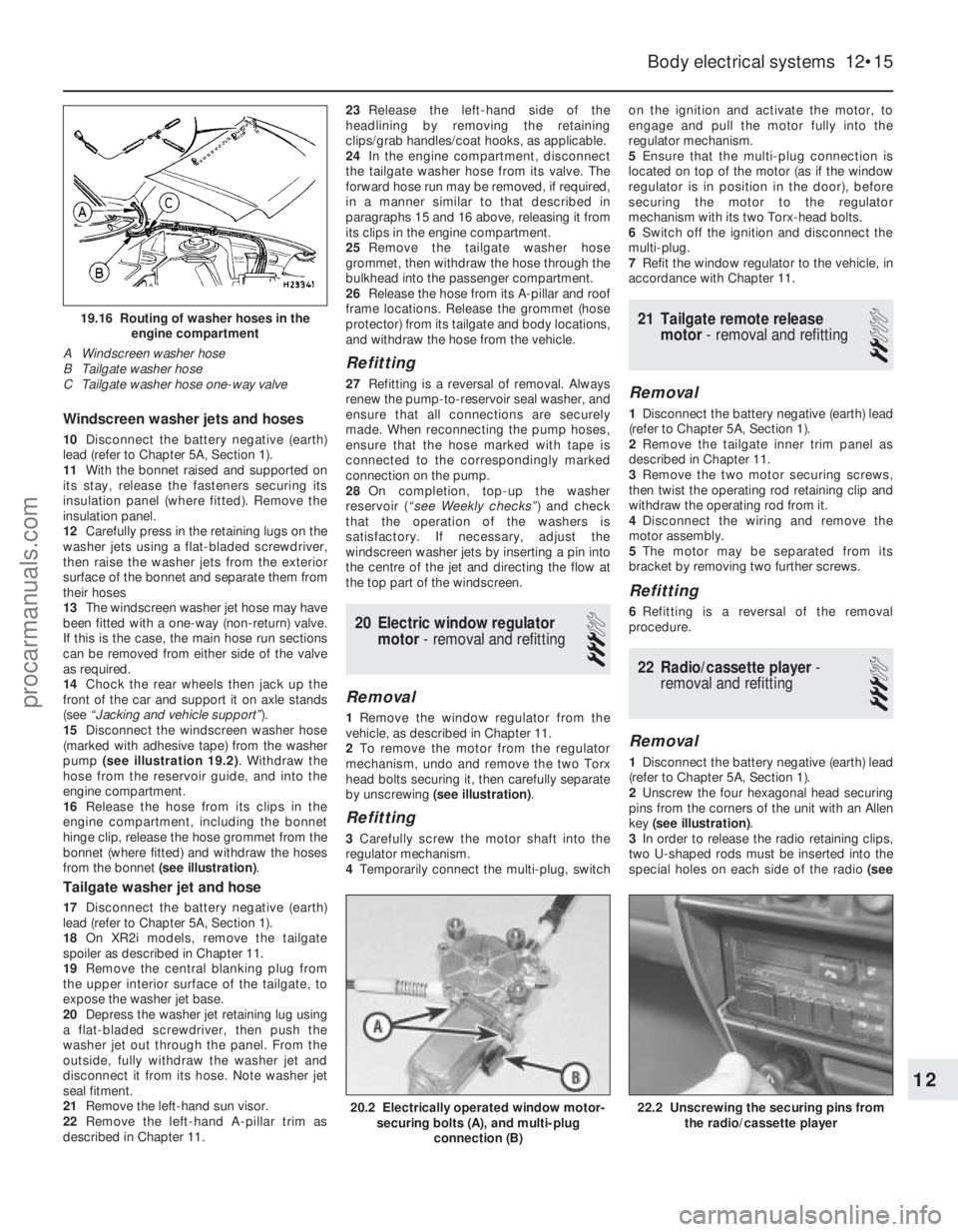
15 Disconnect the windscreen washer hose
(marked with adhesive tape) from the washer
pump (see illustration 19.2) . Withdraw the
hose from the reservoir guide, and into the
engine compartment.
16 Release the hose from its clips in the
engine compartment, including the bonnet
hinge clip, release the hose grommet from the
bonnet (where fitted) and withdraw the hoses
from the bonnet (see illustration) .
Tailgate washer jet and hose
17Disconnect the battery negative (earth)
lead (refer to Chapter 5A, Section 1).
18 On XR2i models, remove the tailgate
spoiler as described in Chapter 11.
19 Remove the central blanking plug from
the upper interior surface of the tailgate, to
expose the washer jet base.
20 Depress the washer jet retaining lug using
a flat-bladed screwdriver, then push the
washer jet out through the panel. From the
outside, fully withdraw the washer jet and
disconnect it from its hose. Note washer jet
seal fitment.
21 Remove the left-hand sun visor.
22 Remove the left-hand A-pillar trim as
described in Chapter 11. 23
Release the left-hand side of the
headlining by removing the retaining
clips/grab handles/coat hooks, as applicable.
24 In the engine compartment, disconnect
the tailgate washer hose from its valve. The
forward hose run may be removed, if required,
in a manner similar to that described in
paragraphs 15 and 16 above, releasing it from
its clips in the engine compartment.
25 Remove the tailgate washer hose
grommet, then withdraw the hose through the
bulkhead into the passenger compartment.
26 Release the hose from its A-pillar and roof
frame locations. Release the grommet (hose
protector) from its tailgate and body locations,
and withdraw the hose from the vehicle.
Refitting
27 Refitting is a reversal of removal. Always
renew the pump-to-reservoir seal washer, and
ensure that all connections are securely
made. When reconnecting the pump hoses,
ensure that the hose marked with tape is
connected to the correspondingly marked
connection on the pump.
28 On completion, top-up the washer
reservoir ( “see Weekly checks” ) and check
that the operation of the washers is
satisfactory. If necessary, adjust the
windscreen washer jets by inserting a pin into
the centre of the jet and directing the flow at
the top part of the windscreen.
20 Electric window regulator motor - removal and refitting
3
Removal
1Remove the window regulator from the
vehicle, as described in Chapter 11.
2 To remove the motor from the regulator
mechanism, undo and remove the two Torx
head bolts securing it, then carefully separate
by unscrewing (see illustration) .
Refitting
3Carefully screw the motor shaft into the
regulator mechanism.
4 Temporarily connect the multi-plug, switch on the ignition and activate the motor, to
engage and pull the motor fully into the
regulator mechanism.
5
Ensure that the multi-plug connection is
located on top of the motor (as if the window
regulator is in position in the door), before
securing the motor to the regulator
mechanism with its two Torx-head bolts.
6 Switch off the ignition and disconnect the
multi-plug.
7 Refit the window regulator to the vehicle, in
accordance with Chapter 11.
21 Tailgate remote release motor - removal and refitting
2
Removal
1Disconnect the battery negative (earth) lead
(refer to Chapter 5A, Section 1).
2 Remove the tailgate inner trim panel as
described in Chapter 11.
3 Remove the two motor securing screws,
then twist the operating rod retaining clip and
withdraw the operating rod from it.
4 Disconnect the wiring and remove the
motor assembly.
5 The motor may be separated from its
bracket by removing two further screws.
Refitting
6 Refitting is a reversal of the removal
procedure.
22 Radio/cassette player -
removal and refitting
3
Removal
1 Disconnect the battery negative (earth) lead
(refer to Chapter 5A, Section 1).
2 Unscrew the four hexagonal head securing
pins from the corners of the unit with an Allen
key (see illustration) .
3 In order to release the radio retaining clips,
two U-shaped rods must be inserted into the
special holes on each side of the radio (see
Body electrical systems 12•15
19.16 Routing of washer hoses in the
engine compartment
A Windscreen washer hose
B Tailgate washer hose
C Tailgate washer hose one-way valve
22.2 Unscrewing the securing pins from the radio/cassette player20.2 Electrically operated window motor-securing bolts (A), and multi-plug
connection (B)
12
1595Ford Fiesta Remakeprocarmanuals.com
http://vnx.su
Page 250 of 296
27 Anti-theft systems-
general information
Anti-theft alarm system
1 This system provides an added form of
vehicle security. When the system is
activated, the alarm will sound if the vehicle is
broken into through any one of the doors, the
bonnet, or tailgate. The alarm will also be
triggered if the ignition system is turned on or
the radio/cassette disconnected whilst the
system is activated.
2 This system is activated/de-activated
whenever one of the front doors is
locked/unlocked by the key. The system
operates on all doors, the bonnet and tailgate
whenever each door is individually locked (or,
in the case of central locking, when the central
locking is engaged). In addition, the
ignition/starting system is also immobilised
when the system is activated.
3 A further security feature included is that
even though the battery may be disconnected
whilst the system is activated, the alarm
activation continues as soon as the battery is
reconnected. Because of this feature, it is
important to ensure that the system is de-
activated before disconnecting the battery at
any time, such as when working on the
vehicle.
4 The system incorporates a diagnostic mode
to enable Ford technicians to quickly identify
any faults in the system. In the event of a
system malfunction, any testing or
component removal and refitting should be
entrusted to a Ford dealer.
Passive Anti-Theft System
(PATS)
5 From 1994 model year onwards, a Passive
Anti-Theft System (PATS) is fitted. This
system, (which works independently of the
standard alarm system) is a vehicle
immobiliser which prevents the engine from
being started unless a specific code,
programmed into the ignition key, is
recognised by the PATS transceiver.
6 The PATS transceiver, fitted around the
ignition switch, decodes a signal from the
ignition key as the key is turned from position
“O” to position “II”. If the coded signal
matches that stored in the memory of the
PATS module, the engine will start. If the
signal is not recognised, the engine will crank
on the starter but will not fire.
28 Air bag (driver’s side) -
removal and refitting
4
Warning: Handle the air bag
with extreme care as a
precaution against personal
injury, and always hold it with the cover facing away from your body. If in
doubt concerning any proposed work
involving the air bag or its control circuitry,
consult a Ford dealer or other qualified
specialist.
Removal
1
Disconnect the battery negative (earth) lead
(refer to Chapter 5A, Section 1). Warning: Before proceeding,
wait a minimum of 15 minutes,
as a precaution against
accidental firing of the air bag.
This period ensures that any stored energy
in the back-up capacitor is dissipated.
2 Undo the screws, and remove the steering
column lower shroud.
3 Undo the two external screws and the two
internal screws and remove the steering
column upper shroud.
4 Turn the steering wheel as necessary so
that one of the air bag module retaining bolts
becomes accessible from the rear of the
steering wheel. Undo the bolt, then turn the
steering wheel again until the second bolt is
accessible. Undo this bolt also.
5 Withdraw the air bag module from the
steering wheel far enough to access the
wiring multi-plug. Some force may be needed
to free the module from the additional steering
wheel spoke retainers.
6 Disconnect the multi-plug from the rear of
the module, and remove the module from the
vehicle. Warning: Position the air bag
module in a safe place, with the
mechanism facing downwards
as a precaution against
accidental operation.
Warning: Do not attempt to
open or repair the air bag unit,
or apply any electrical current to
it. Do not use any air bag which
is visibly damaged or which has been
tampered with.
Refitting
7 Refitting is a reversal of the removal
procedure.
29 Air bag (passenger’s side) -
removal and refitting
4
Warning: Handle the air bag
with extreme care as a
precaution against personal
injury, and always hold it with
the cover facing away from your body. If in
doubt concerning any proposed work
involving the air bag or its control circuitry,
consult a Ford dealer or other qualified
specialist.
Removal
1 Disconnect the battery negative (earth) lead
(refer to Chapter 5A, Section 1). Warning: Before proceeding,
wait a minimum of 15 minutes,
as a precaution against
accidental firing of the air bag.
This period ensures that any stored energy
in the back-up capacitor is dissipated.
2 Remove the facia as described in Chap-
ter 11.
3 Undo the air bag module retaining nuts and
remove the unit from the facia. Warning: Position the air bag
module in a safe place, with the
mechanism facing downwards
as a precaution against
accidental operation.
Warning: Do not attempt to
open or repair the air bag unit,
or apply any electrical current to
it. Do not use any air bag which
is visibly damaged or which has been
tampered with.
Refitting
4 Refitting is a reversal of the removal
procedure.
30 Air bag control module -
removal and refitting
4
Removal
1 Disconnect the battery negative (earth) lead
(refer to Chapter 5A, Section 1). Warning: Before proceeding,
wait a minimum of 15 minutes,
as a precaution against
accidental firing of the air bag
unit. This period ensures that any stored
energy in the back-up capacitor is
dissipated.
2 Remove the module access cover from the
rear of the glovebox.
3 Press the module wiring multi-plug locking
tag upwards then pivot the retaining strap
over and disconnect the multi-plug.
4 Remove the facia as described in Chap-
ter 11.
5 Undo the three retaining bolts and remove
the module from its location.
Refitting
6 Refitting is a reversal of the removal
procedure.
31 Air bag clock spring -
removal and refitting
4
Removal
1 Remove the steering wheel as described in
Chapter 10.
2 Undo the three retaining screws, and
remove the clock spring from the steering
wheel. As the unit is withdrawn, note which
aperture in the steering wheel the air bag
Body electrical systems 12•17
12
1595Ford Fiesta Remakeprocarmanuals.com
http://vnx.su