1989 FORD FIESTA tire type
[x] Cancel search: tire typePage 203 of 296
3Unscrew and remove the upper mounting
through-bolt and nut.
4 Withdraw the upper mounting cup and the
spring seat.
5 The suspension strut and coil spring can now
be separated. If the coil spring or strut is to be
renewed, the original coil spring must be
released from the compressor. If it is to be re-
used, the coil spring can be left in compression.
Examination
6 With the strut assembly now completely
dismantled, examine the mounting
components for wear, damage or deformation.
Renew any of the components as necessary.
7 Examine the strut for signs of fluid leakage.
Check the strut piston for signs of pitting
along its entire length, and check the strut
body for signs of damage or deterioration of
the mountings. Test the operation of the strut,
holding it in an upright position, by moving the
piston through a full stroke, and then through
short strokes of 50 to 100 mm. In both cases,
the resistance felt should be smooth and
continuous. If the resistance is jerky, or
uneven, or if there is any visible sign of wear
or damage to the strut, renewal is necessary.
Reassembly
8 Reassembly is a reversal of the dismantling
procedure but note the following points: a) When the spring is located over the
suspension strut, the spring seat, cup and
through-bolt fitted, tighten the retaining
bolt to the specified torque.
b) When reassembled, check that the upper
and lower spring tails are correctly
engaged with their spring seats before
removing the spring compressor.
12 Rear axle (all models except
Courier) -
removal and refitting
3
Removal
1 Chock the front wheels then jack up the
rear of the car and support it on axle stands
(see “Jacking and Vehicle Support” ). Remove
the rear roadwheels.
2 Refer to Chapter 9 for details, and disconnect
the handbrake cable equaliser from the primary
cable. Remove the handbrake rear cable from
its adjuster and its fixed body locations.
3 Disconnect the rear brake flexible hydraulic
brake hoses from their rigid line connections.
Clamp the hoses before disconnecting them,
to minimise the fluid loss and air entry into the
hydraulic system (see Chapter 9 for details).
4 On ABS-equipped models, undo the
retaining nuts and detach the ABS load-
apportioning valve operating links from the
axle beam. Do not remove the load-
apportioning valve (see Chapter 9).
5 Locate suitable jacks or axle stands under
the axle beam to support its weight (not to lift
it), then unscrew the four mounting bracket
bolts each side. 6
Unscrew and remove the strut-to-axle
mounting bolt each side.
7 Check that all associated fittings are clear,
then lower the axle and remove it from under
the vehicle.
8 If the twist beam axle has been damaged, it
must be renewed. Refer to Chapter 9 for
details on removing the rear brakes from the
axle. To remove the front mounting/pivot
brackets from the axle, unscrew the pivot bolt.
Refitting
9 Refitting is a reversal of the removal
procedure, but note the following: a) Reconnect the axle at the front floor mountings first, and tighten the retaining
bolts to the specified torque.
b) Reconnect the axle to the suspension struts, but do not fully retighten the securing
bolts until after the vehicle is lowered to the
ground and is standing on its wheels.
c) Ensure that all brake fluid line connections are clean before reconnecting them. Refer
to the appropriate Sections in Chapter 9
for specific details on reconnecting the
brake lines, bleeding the brake hydraulic
system, and for reconnecting the
handbrake cable and its adjustment.
d) When the vehicle is lowered and is standing
on its wheels, tighten the suspension
fastenings to their specified torque settings.
13 Rear axle pivot bushes (all
models except Courier) -
renewal
3
Note: Two different types of pivot bushes
have been fitted during the course of Fiesta
production. It is understood that once stocks
of the early type are exhausted, only the latter
type will be supplied by Ford parts dealers. If
renewing pivot bushes on a pre-April 1990
model, and only the later type bushes are
available, fit the new bushes as described
from paragraph 15 onward.
Pre-April 1990 models
1 Chock the front wheels then jack up the
rear of the car and support it on axle stands
(see “Jacking and Vehicle Support” ).2
Position a suitable support (preferably
adjustable) under the axle twist beam so that
it is capable of carrying the weight of the axle
(not the weight of the vehicle).
3 On ABS-equipped models, undo the
retaining nuts and detach the ABS load-
apportioning valve operating links from the
axle beam. Do not remove the load-
apportioning valve (see Chapter 9).
4 Unscrew the nuts, withdraw the pivot bolts,
then lower the rear axle so that the bushes are
clear of their mounting brackets (see
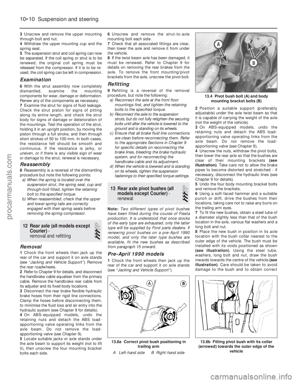
illustration) . Take care not to allow the brake
pipes to become distorted and stretched - if
necessary, disconnect the hydraulic lines (see
Chapter 9 for details).
5 Undo the four body mounting bracket bolts
and remove the brackets.
6 Using a soft-faced hammer and a suitable
punch or drift, drive the bushes from their
locations, taking care not to raise any burrs on
the trailing arm eyes.
7 To fit the new bushes, obtain a steel tube of
a diameter slightly less than that of the bush
location in the axle, various flat washers and a
long bolt and nut.
8 Place the new bush in position in its axle
location with the bush collar nearest to the
outer edge of the vehicle. The bush must be
installed with its voids positioned as shown
(see illustration) . Using the steel tube,
washers, long bolt and nut, draw the bush
inwards towards the centre of the vehicle (see
illustration) . Care should be taken to avoid
damage to the bush and to obtain correct
10•10 Suspension and steering
13.8b Fitting pivot bush with its collar
(arrowed) towards the outer edge of the vehicle13.8a Correct pivot bush positioning intrailing arm
A Left-hand side B Right-hand side
13.4 Pivot bush bolt (A) and body mounting bracket bolts (B)
1595Ford Fiesta Remakeprocarmanuals.com
http://vnx.su
Page 279 of 296
1595 Ford Fiesta Remake
MOT test checksREF•13
REF
MExamine the handbrake mechanism,
checking for frayed or broken cables,
excessive corrosion, or wear or insecurity of
the linkage. Check that the mechanism works
on each relevant wheel, and releases fully,
without binding.
M It is not possible to test brake efficiency
without special equipment, but a road test can
be carried out later to check that the vehicle
pulls up in a straight line.
Fuel and exhaust systems
M Inspect the fuel tank (including the filler
cap), fuel pipes, hoses and unions. All
components must be secure and free fr om
leaks.
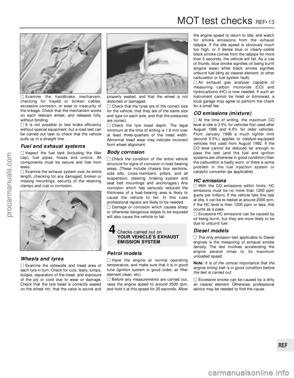
M Examine the exhaust system over its entire
length, checking for any damaged, broken or
missing mountings, security of the retaining
clamps and rust or corrosion.
Wheels and tyres
M Examine the sidewalls and tread area of
each tyre in turn. Check for cuts, tears, lumps,
bulges, separation of the tread, and exposure
of the ply or cord due to wear or damage.
Check that the tyre bead is correctly seated
on the wheel rim, that the valve is sound and pr
operly seated, and that the wheel is not
distorted or damaged.
M Check that the tyres are of the correct size
for the vehicle, that they are of the same size
and type on each axle, and that the pressur es
ar e correct.
M Check the tyre tread depth. The legal
minimum at the time of writing is 1.6 mm over
at least three-quarters of the tread width.
Abnormal tread wear may indicate incorrect
fr ont wheel alignment.
Body corrosion
M Check the condition of the entire vehicle
structur e for signs of corrosion in load-bearing
ar eas. (These include chassis box sections,
side sills, cross-members, pillars, and all
suspension, steering, braking system and
seat belt mountings and anchorages.) Any
corrosion which has seriously reduced the
thickness of a load-bearing area is likely to
cause the vehicle to fail. In this case
pr ofessional repairs are likely to be needed.
M Damage or corrosion which causes sharp
or otherwise dangerous edges to be exposed
will also cause the vehicle to fail.
Petrol models
M Have the engine at normal operating
temperatur e, and make sure that it is in good
tune (ignition system in good order, air filter
element clean, etc).
M Befor e any measurements are carried out,
raise the engine speed to around 2500 rpm,
and hold it at this speed for 20 seconds. Allow the engine speed to return to idle, and watch
for smoke emissions from the exhaust
tailpipe. If the idle speed is obviously much
too high, or if dense blue or clearly-visible
black smoke comes from the tailpipe for more
than 5 seconds, the vehicle will fail. As a rule
of thumb, blue smoke signifies oil being burnt
(engine wear) while black smoke signifies
unbur nt fuel (dirty air cleaner element, or other
carbur ettor or fuel system fault).
M An exhaust gas analyser capable of
measuring carbon monoxide (CO) and
hydr ocarbons (HC) is now needed. If such an
instrument cannot be hired or borrowed, a
local garage may agree to perform the check
for a small fee.
CO emissions (mixture)
M At the time of writing, the maximum CO
level at idle is 3.5% for vehicles first used after
August 1986 and 4.5% for older vehicles.
Fr om January 1996 a much tighter limit
(ar ound 0.5%) applies to catalyst-equipped
vehicles first used from August 1992. If the
CO level cannot be reduced far enough to
pass the test (and the fuel and ignition
systems are otherwise in good condition) then
the carburettor is badly worn, or there is some
pr oblem in the fuel injection system or
catalytic converter (as applicable).
HC emissionsM With the CO emissions within limits, HC
emissions must be no more than 1200 ppm
(parts per million). If the vehicle fails this test
at idle, it can be re-tested at around 2000 rpm;
if the HC level is then 1200 ppm or less, this
counts as a pass.
M Excessive HC emissions can be caused by
oil being burnt, but they are more likely to be
due to unburnt fuel.
Diesel models
M The only emission test applicable to Diesel
engines is the measuring of exhaust smoke
density . The test involves accelerating the
engine several times to its maximum
unloaded speed.
Note: It is of the utmost importance that the
engine timing belt is in good condition before
the test is carried out.
M
Excessive smoke can be caused by a dirty
air cleaner element. Otherwise, professional
advice may be needed to find the cause.
4Checks carried out on
YOUR VEHICLE’S EXHAUST
EMISSION SYSTEM
procarmanuals.com
http://vnx.su
Page 291 of 296
1595 Ford Fiesta Remake
Glossary of technical termsREF•25
REF
JJump startStarting the engine of a vehicle
with a discharged or weak battery by
attaching jump leads from the weak battery to
a charged or helper battery.
LLoad Sensing Proportioning Valve (LSPV) A
brake hydraulic system control valve that
works like a proportioning valve, but also
takes into consideration the amount of weight
carried by the rear axle.
Locknut A nut used to lock an adjustment
nut, or other threaded component, in place.
For example, a locknut is employed to keep
the adjusting nut on the rocker arm in
position.
Lockwasher A form of washer designed to
pr event an attaching nut from working loose.
MMacPherson strut A type of front
suspension system devised by Earle
MacPherson at Ford of England. In its original
form, a simple lateral link with the anti-roll bar
cr eates the lower control arm. A long strut - an
integral coil spring and shock absorber - is
mounted between the body and the steering
knuckle. Many modern so-called MacPherson
strut systems use a conventional lower A-arm
and don’t rely on the anti-roll bar for location. Multimeter An electrical test instrument with
the capability to measure voltage, current and
resistance.
NNOx Oxides of Nitrogen. A common toxic
pollutant emitted by petrol and diesel engines
at higher temperatures.
OOhm The unit of electrical resistance. One
volt applied to a resistance of one ohm will
pr oduce a current of one amp.
Ohmmeter An instrument for measuring
electrical resistance.
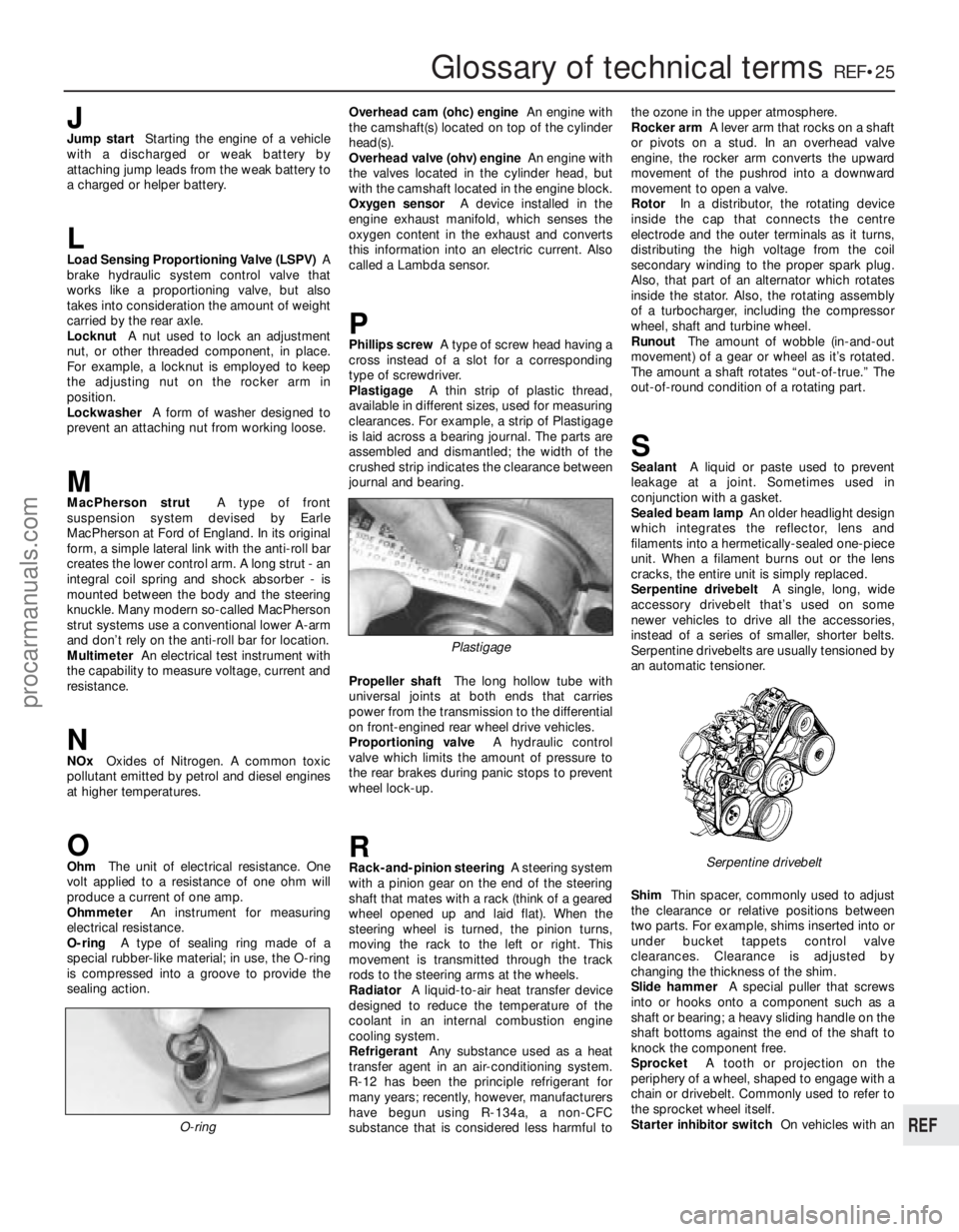
O-ring A type of sealing ring made of a
special rubber-like material; in use, the O-ring
is compressed into a groove to provide the
sealing action. Overhead cam (ohc) engine
An engine with
the camshaft(s) located on top of the cylinder
head(s).
Overhead valve (ohv) engine An engine with
the valves located in the cylinder head, but
with the camshaft located in the engine block.
Oxygen sensor A device installed in the
engine exhaust manifold, which senses the
oxygen content in the exhaust and converts
this information into an electric current. Also
called a Lambda sensor.
PPhillips screw A type of screw head having a
cr oss instead of a slot for a corresponding
type of screwdriver.
Plastigage A thin strip of plastic thread,
available in different sizes, used for measuring clearances. For example, a strip of Plastigage
is laid across a bearing journal. The parts areassembled and dismantled; the width of the
crushed strip indicates the clearance between
jour nal and bearing.
Pr opeller shaft The long hollow tube with
universal joints at both ends that carries
power from the transmission to the differential on front-engined rear wheel drive vehicles.
Pr oportioning valve A hydraulic control
valve which limits the amount of pressure to
the rear brakes during panic stops to prevent
wheel lock-up.
RRack-and-pinion steering A steering system
with a pinion gear on the end of the steering
shaft that mates with a rack (think of a geared
wheel opened up and laid flat). When the
steering wheel is turned, the pinion turns,
moving the rack to the left or right. This
movement is transmitted through the track
r ods to the steering arms at the wheels.
Radiator A liquid-to-air heat transfer device
designed to reduce the temperature of the
coolant in an internal combustion engine
cooling system.
Refrigerant Any substance used as a heat
transfer agent in an air-conditioning system.
R-12 has been the principle refrigerant for
many years; recently, however, manufacturers
have begun using R-134a, a non-CFC
substance that is considered less harmful to the ozone in the upper atmosphere.
Rocker arm
A lever arm that rocks on a shaft
or pivots on a stud. In an overhead valve
engine, the rocker arm converts the upward
movement of the pushrod into a downward
movement to open a valve.
Rotor In a distributor, the rotating device
inside the cap that connects the centre
electr ode and the outer terminals as it turns,
distributing the high voltage from the coil
secondary winding to the proper spark plug.
Also, that part of an alternator which rotates
inside the stator. Also, the rotating assembly
of a turbocharger, including the compressor
wheel, shaft and turbine wheel.
Runout The amount of wobble (in-and-out
movement) of a gear or wheel as it’ s rotated.
The amount a shaft rotates “out-of-true.” The
out-of-r ound condition of a rotating part.
SSealant A liquid or paste used to prevent
leakage at a joint. Sometimes used in
conjunction with a gasket.
Sealed beam lamp An older headlight design
which integrates the reflector, lens and
filaments into a hermetically-sealed one-piece
unit. When a filament burns out or the lens
cracks, the entire unit is simply replaced.
Serpentine drivebelt A single, long, wide
accessory drivebelt that’s used on some
newer vehicles to drive all the accessories,
instead of a series of smaller, shorter belts.
Serpentine drivebelts are usually tensioned by
an automatic tensioner.
Shim Thin spacer, commonly used to adjust
the clearance or relative positions between
two parts. For example, shims inserted into or
under bucket tappets control valve
clearances. Clearance is adjusted by
changing the thickness of the shim.
Slide hammer A special puller that screws
into or hooks onto a component such as a
shaft or bearing; a heavy sliding handle on the
shaft bottoms against the end of the shaft to
knock the component free.
Sprocket A tooth or projection on the
periphery of a wheel, shaped to engage with a
chain or drivebelt. Commonly used to refer to
the sprocket wheel itself.
Starter inhibitor switch On vehicles with an
O-ring
Serpentine drivebelt
Plastigage
procarmanuals.com
http://vnx.su