1989 FORD FIESTA steering wheel adjustment
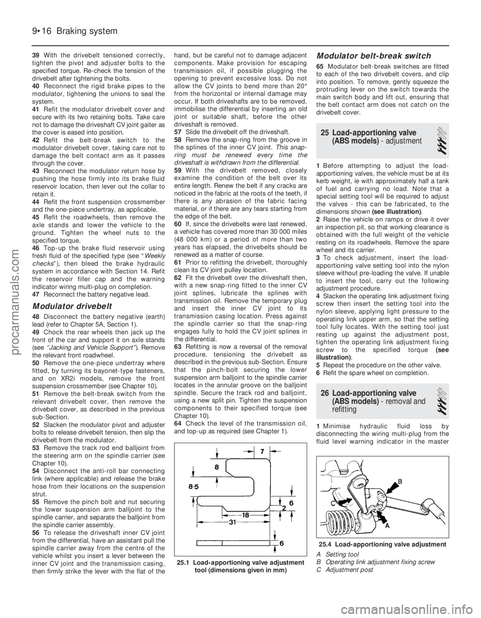
[x] Cancel search: steering wheel adjustmentPage 78 of 296
7Refer to the relevant Part of Chapter 4 for
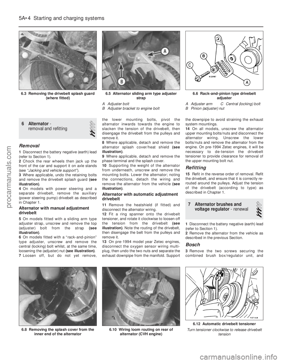
details, and disconnect the accelerator cable
from the throttle linkage and support/adjuster
bracket. Where applicable, also disconnect
the choke cable. Position the cable(s) out of
the way.
8 On carburettor models, disconnect the fuel
supply hose from the fuel pump, and the
return hose from the carburettor.
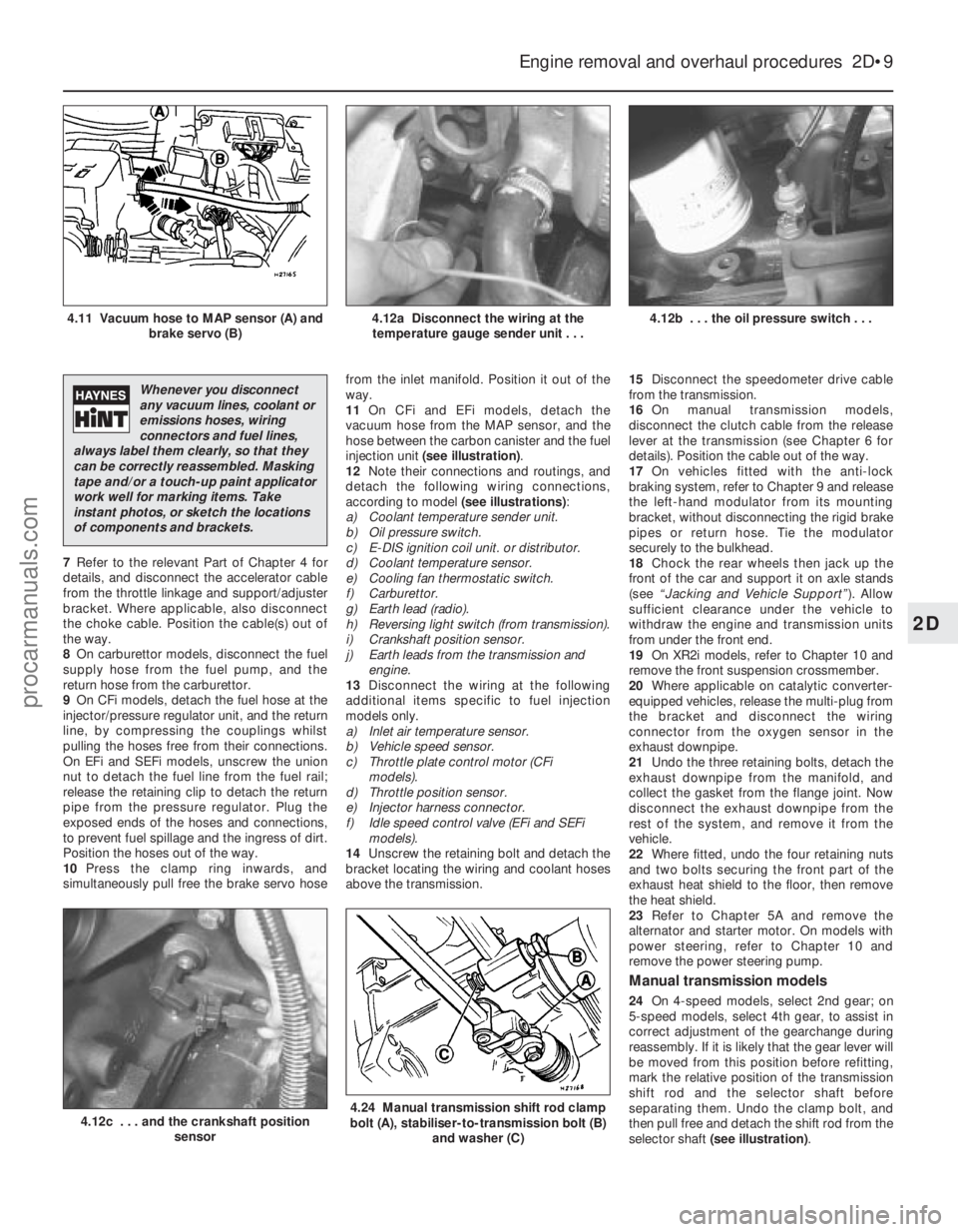
9 On CFi models, detach the fuel hose at the
injector/pressure regulator unit, and the return
line, by compressing the couplings whilst
pulling the hoses free from their connections.
On EFi and SEFi models, unscrew the union
nut to detach the fuel line from the fuel rail;
release the retaining clip to detach the return
pipe from the pressure regulator. Plug the
exposed ends of the hoses and connections,
to prevent fuel spillage and the ingress of dirt.
Position the hoses out of the way.
10 Press the clamp ring inwards, and
simultaneously pull free the brake servo hose from the inlet manifold. Position it out of the
way.
11
On CFi and EFi models, detach the
vacuum hose from the MAP sensor, and the
hose between the carbon canister and the fuel
injection unit (see illustration) .
12 Note their connections and routings, and
detach the following wiring connections,
according to model (see illustrations):
a) Coolant temperature sender unit.
b) Oil pressure switch.
c) E-DIS ignition coil unit. or distributor.
d) Coolant temperature sensor.
e) Cooling fan thermostatic switch.
f) Carburettor.
g) Earth lead (radio).
h) Reversing light switch (from transmission).
i) Crankshaft position sensor.
j) Earth leads from the transmission and engine.
13 Disconnect the wiring at the following
additional items specific to fuel injection
models only.
a) Inlet air temperature sensor.
b) Vehicle speed sensor.
c) Throttle plate control motor (CFi models).
d) Throttle position sensor.
e) Injector harness connector.
f) Idle speed control valve (EFi and SEFi models).
14 Unscrew the retaining bolt and detach the
bracket locating the wiring and coolant hoses
above the transmission. 15
Disconnect the speedometer drive cable
from the transmission.
16 On manual transmission models,
disconnect the clutch cable from the release
lever at the transmission (see Chapter 6 for
details). Position the cable out of the way.
17 On vehicles fitted with the anti-lock
braking system, refer to Chapter 9 and release
the left-hand modulator from its mounting
bracket, without disconnecting the rigid brake
pipes or return hose. Tie the modulator
securely to the bulkhead.
18 Chock the rear wheels then jack up the
front of the car and support it on axle stands
(see “Jacking and Vehicle Support” ). Allow
sufficient clearance under the vehicle to
withdraw the engine and transmission units
from under the front end.
19 On XR2i models, refer to Chapter 10 and
remove the front suspension crossmember.
20 Where applicable on catalytic converter-
equipped vehicles, release the multi-plug from
the bracket and disconnect the wiring
connector from the oxygen sensor in the
exhaust downpipe.
21 Undo the three retaining bolts, detach the
exhaust downpipe from the manifold, and
collect the gasket from the flange joint. Now
disconnect the exhaust downpipe from the
rest of the system, and remove it from the
vehicle.
22 Where fitted, undo the four retaining nuts
and two bolts securing the front part of the
exhaust heat shield to the floor, then remove
the heat shield.
23 Refer to Chapter 5A and remove the
alternator and starter motor. On models with
power steering, refer to Chapter 10 and
remove the power steering pump.
Manual transmission models
24 On 4-speed models, select 2nd gear; on
5-speed models, select 4th gear, to assist in
correct adjustment of the gearchange during
reassembly. If it is likely that the gear lever will
be moved from this position before refitting,
mark the relative position of the transmission
shift rod and the selector shaft before
separating them. Undo the clamp bolt, and
then pull free and detach the shift rod from the
selector shaft (see illustration) .
Engine removal and overhaul procedures 2D•9
4.12b . . . the oil pressure switch . . .4.12a Disconnect the wiring at the
temperature gauge sender unit . . .4.11 Vacuum hose to MAP sensor (A) and brake servo (B)
4.24 Manual transmission shift rod clamp
bolt (A), stabiliser-to-transmission bolt (B)
and washer (C)4.12c . . . and the crankshaft position sensor
2D
1595Ford Fiesta Remake
Whenever you disconnect
any vacuum lines, coolant or
emissions hoses, wiring
connectors and fuel lines,
always label them clearly, so that they
can be correctly reassembled. Masking
tape and/or a touch-up paint applicator
work well for marking items. Take
instant photos, or sketch the locations
of components and brackets.
procarmanuals.com
http://vnx.su
Page 163 of 296
6 Alternator-
removal and refitting
2
Removal
1 Disconnect the battery negative (earth) lead
(refer to Section 1).
2 Chock the rear wheels then jack up the
front of the car and support it on axle stands
(see “Jacking and vehicle support” ).
3 Where applicable, undo the retaining bolts
and remove the drivebelt splash guard (see
illustration) .
4 On models with power steering and a
separate drivebelt, remove the auxiliary
(power steering pump) drivebelt as described
in Chapter 1.
Alternator with manual adjustment
drivebelt
5 On models fitted with a sliding arm type
adjuster strap, unscrew and remove the top
(adjuster) bolt from the strap (see
illustration) .
6 On models fitted with a “rack-and-pinion”
type adjuster, unscrew and remove the
central (locking) bolt whilst, at the same time,
loosening the (adjuster) nut (see illustration).
7 Loosen off, but do not yet remove, the lower mounting bolts, pivot the
alternator inwards towards the engine to
slacken the tension of the drivebelt, then
disengage the drivebelt from the pulleys and
remove it.
8
Where applicable, detach and remove the
alternator splash cover/heat shield (see
illustration) .
9 Where applicable, detach and remove the
phase terminal and the splash cover.
10 Supporting the weight of the alternator
from underneath, unscrew and remove the
mounting bolts. Lower the alternator; noting
the connections, detach the wiring and
remove the alternator from the vehicle (see
illustration) .
Alternator with automatic adjustment
drivebelt
11Remove the heatshield (if fitted) and
disconnect the alternator wiring.
12 Fit a ring spanner onto the drivebelt
tensioner, and rotate it clockwise to loosen off
the tension from the drivebelt (see
illustration) . Note the routing of the drivebelt,
then disengage the belt from the pulleys and
remove it.
13 On pre-1994 model year Zetec engines,
disconnect the oxygen sensor wiring multi-
plug, then undo the two nuts and separate the
exhaust downpipe from the manifold. Support the downpipe to avoid straining the exhaust
system mountings.
14
On all models, unscrew the alternator
upper mounting bolts/nuts and disconnect the
alternator wiring. Unscrew the lower
bolts/nuts and remove the alternator from the
engine. On pre-1994 Zetec engines, it will be
necessary to de-tension the drivebelt
tensioner to provide clearance for removal of
the upper mounting bolt nut.
Refitting
15 Refit in the reverse order of removal. Refit
the drivebelt, and ensure that it is correctly re-
routed around the pulleys. Adjust the tension
of the drivebelt (according to type) as
described in Chapter 1.
7 Alternator brushes and voltage regulator - renewal
3
1Disconnect the battery negative (earth) lead
(refer to Section 1).
2 Remove the alternator from the vehicle as
described in the previous Section.
Bosch
3 Remove the two screws securing the
combined brush box/regulator unit, and
5A•4 Starting and charging systems
6.12 Automatic drivebelt tensioner
Turn tensioner clockwise to release drivebelt tension
6.10 Wiring loom routing on rear ofalternator (CVH engine)6.8 Removing the splash cover from the inner end of the alternator
6.6 Rack-and-pinion type drivebelt adjuster
A Adjuster arm C Central (locking) bolt
B Pinion (adjuster) nut6.5 Alternator sliding arm type adjuster strap
A Adjuster bolt
B Adjuster bracket to engine bolt6.3 Removing the drivebelt splash guard (where fitted)
1595Ford Fiesta Remakeprocarmanuals.com
http://vnx.su
Page 191 of 296
39With the drivebelt tensioned correctly,
tighten the pivot and adjuster bolts to the
specified torque. Re-check the tension of the
drivebelt after tightening the bolts.
40 Reconnect the rigid brake pipes to the
modulator, tightening the unions to seal the
system.
41 Refit the modulator drivebelt cover and
secure with its two retaining bolts. Take care
not to damage the driveshaft CV joint gaiter as
the cover is eased into position.
42 Refit the belt-break switch to the
modulator drivebelt cover, taking care not to
damage the belt contact arm as it passes
through the cover.
43 Reconnect the modulator return hose by
pushing the hose firmly into its brake fluid
reservoir location, then lever out the collar to
retain it.
44 Refit the front suspension crossmember
and the one-piece undertray, as applicable.
45 Refit the roadwheels, then remove the
axle stands and lower the vehicle to the
ground. Tighten the wheel nuts to the
specified torque.
46 Top-up the brake fluid reservoir using
fresh fluid of the specified type (see “ Weekly
checks ”), then bleed the brake hydraulic
system in accordance with Section 14. Refit
the reservoir filler cap and the warning
indicator wiring multi-plug on completion.
47 Reconnect the battery negative lead.
Modulator drivebelt
48Disconnect the battery negative (earth)
lead (refer to Chapter 5A, Section 1).
49 Chock the rear wheels then jack up the
front of the car and support it on axle stands
(see “Jacking and Vehicle Support” ). Remove
the relevant front roadwheel.
50 Remove the one-piece undertray where
fitted, by turning its bayonet-type fasteners,
and on XR2i models, remove the front
suspension crossmember (see Chapter 10).
51 Remove the belt-break switch from the
relevant drivebelt cover, then remove the
drivebelt cover, as described in the previous
sub-Section.
52 Slacken the modulator pivot and adjuster
bolts to release drivebelt tension, then slip the
drivebelt from the modulator.
53 Remove the track rod end balljoint from
the steering arm on the spindle carrier (see
Chapter 10).
54 Disconnect the anti-roll bar connecting
link (where applicable) and release the brake
hose from their locations on the suspension
strut.
55 Remove the pinch bolt and nut securing
the lower suspension arm balljoint to the
spindle carrier, and separate the balljoint from
the spindle carrier assembly.
56 To release the driveshaft inner CV joint
from the differential, have an assistant pull the
spindle carrier away from the centre of the
vehicle whilst you insert a lever between the
inner CV joint and the transmission casing,
then firmly strike the lever with the flat of the hand, but be careful not to damage adjacent
components. Make provision for escaping
transmission oil, if possible plugging the
opening to prevent excessive loss. Do not
allow the CV joints to bend more than 20°
from the horizontal or internal damage may
occur. If both driveshafts are to be removed,
immobilise the differential by inserting an old
joint or suitable shaft, before the other
driveshaft is removed.
57
Slide the drivebelt off the driveshaft.
58 Remove the snap-ring from the groove in
the splines of the inner CV joint. This snap-
ring must be renewed every time the
driveshaft is withdrawn from the differential.
59 With the drivebelt removed, closely
examine the condition of the belt over its
entire length. Renew the belt if any cracks are
noticed in the fabric at the roots of the teeth, if
there is any abrasion of the fabric facing
material, or if there are any tears starting from
the edge of the belt.
60 If, since the drivebelts were last renewed,
a vehicle has covered more than 30 000 miles
(48 000 km) or a period of more than two
years has elapsed, the drivebelts should be
renewed as a matter of course.
61 Prior to refitting the drivebelt, thoroughly
clean its CV joint pulley location.
62 Fit the drivebelt over the driveshaft then,
with a new snap-ring fitted to the inner CV
joint splines, lubricate the splines with
transmission oil. Remove the temporary plug
and insert the inner CV joint to its
transmission casing location. Press against
the spindle carrier so that the snap-ring
engages fully to hold the CV joint splines in
the differential.
63 Refitting is now a reversal of the removal
procedure, tensioning the drivebelt as
described in the previous sub-Section. Ensure
that the pinch-bolt securing the lower
suspension arm balljoint to the spindle carrier
locates in the annular groove on the balljoint
spindle. Secure the track rod and balljoint,
using a new split pin. Tighten the suspension
components to their specified torque (see
Chapter 10).
64 Check the level of the transmission oil,
and top-up as required (see Chapter 1).
Modulator belt-break switch
65 Modulator belt-break switches are fitted
to each of the two drivebelt covers, and clip
into position. To remove, gently squeeze the
protruding lever on the switch towards the
main switch body and lift out, ensuring that
the belt contact arm does not catch on the
drivebelt cover.
25 Load-apportioning valve (ABS models) - adjustment
3
1Before attempting to adjust the load-
apportioning valves, the vehicle must be at its
kerb weight, ie with approximately half a tank
of fuel and carrying no load. Note that a
special setting tool will be required to adjust
the valves - this can be fabricated, to the
dimensions shown (see illustration).
2 Raise the vehicle on ramps or drive it over
an inspection pit, so that working clearance is
obtained with the full weight of the vehicle
resting on its roadwheels. Remove the spare
wheel and its carrier.
3 To check adjustment, insert the load-
apportioning valve setting tool into the nylon
sleeve without pre-loading the valve. If unable
to insert the tool, carry out the following
adjustment procedure.
4 Slacken the operating link adjustment fixing
screw then insert the setting tool into the
nylon sleeve, applying light pressure to the
operating link upper arm, so that the setting
tool fully locates. With the setting tool just
resting up against the adjustment post,
tighten the operating link adjustment fixing
screw to the specified torque (see
illustration) .
5 Repeat the procedure on the other valve.
6 Refit the spare wheel on completion.
26 Load-apportioning valve
(ABS models) - removal and
refitting
3
1 Minimise hydraulic fluid loss by
disconnecting the wiring multi-plug from the
fluid level warning indicator in the master
9•16 Braking system
25.4 Load-apportioning valve adjustment
A Setting tool
B Operating link adjustment fixing screw
C Adjustment post
25.1 Load-apportioning valve adjustment tool (dimensions given in mm)
1595Ford Fiesta Remakeprocarmanuals.com
http://vnx.su
Page 194 of 296
10
1595Ford Fiesta Remake
Wheel alignment and steering angles
Front wheel toe setting:Pre-1990 models: Tolerance allowed before resetting required . . . . . . . . . . . . . . . . . 3.0 mm toe-out to 3.0 mm toe-in (0°30’ toe-out to 0°30’ toe-in)
Adjustment setting (if required) . . . . . . . . . . . . . . . . . . . . . . . . . . . . Parallel ± 1.0 mm (0° ± 0°10’)
1990 models onward: All models except Turbo:
Tolerance allowed before resetting required . . . . . . . . . . . . . . \
. . 4.5 mm toe-out to 0.5 mm toe-in (0°45’ toe-out to 0°05’ toe-in)
Adjustment setting (if required) . . . . . . . . . . . . . . . . . . . . . . . . . . 2.0 mm toe-out ± 1.0 mm (0°20’ toe-out ± 0°10’)
Turbo models:
Tolerance allowed before resetting required . . . . . . . . . . . . . . \
. . 4.0 mm toe-out to parallel (0°40’ toe-out to 0°0’)
Adjustment setting (if required) . . . . . . . . . . . . . . . . . . . . . . . . . . 2.0 mm toe-out ± 1.0 mm (0°20’ toe-out ± 0°10’)
Chapter 10
Suspension and steering
Auxiliary drivebelt check and renewal . . . . . . . . . . . . . . .See Chapter 1
Front hub bearings - renewal . . . . . . . . . . . . . . . . . . . . . . . . . . . . . . 3
Front spindle carrier - removal and refitting . . . . . . . . . . . . . . . . . . . 2
Front suspension anti-roll bar - removal and refitting . . . . . . . . . . . . 6
Front suspension crossmember - removal and refitting . . . . . . . . . . 7
Front suspension lower arm - removal and refitting . . . . . . . . . . . . . 8
Front suspension strut - dismantling, examination and reassembly . . 5
Front suspension strut - removal and refitting . . . . . . . . . . . . . . . . . 4
General information . . . . . . . . . . . . . . . . . . . . . . . . . . . . . . . . . . . .\
. . 1
Power steering fluid cooler - removal and refitting . . . . . . . . . . . . . . 26
Power steering fluid level check . . . . . . . . . . . . .See
“Weekly Checks”
Power steering hydraulic system - bleeding . . . . . . . . . . . . . . . . . . . 27
Power steering pump - removal and refitting . . . . . . . . . . . . . . . . . . 25
Rear axle (all models except Courier) - removal and refitting . . . . . . 12
Rear axle pivot bushes (all models except Courier) - renewal . . . . . 13
Rear hub bearings - renewal . . . . . . . . . . . . . . . . . . . . . . . . . . . . . . . 9
Rear shock absorber (Courier models) - removal, examination and refitting . . . . . . . . . . . . . . . . . . . . . . . . . . . . . . . . . . . .\
. . . . . . 16 Rear strut (all models except Courier) - dismantling, examination
and reassembly . . . . . . . . . . . . . . . . . . . . . . . . . . . . . . . . . . . .\
. . . 11
Rear strut (all models except Courier) - removal and refitting . . . . . 10
Rear suspension anti-roll bar (all models except Courier) - removal and refitting . . . . . . . . . . . . . . . . . . . . . . . . . . . . . . . . . . . 14
Rear suspension assembly (Courier models) - removal and refitting . . 17
Rear suspension components (Courier models) - general . . . . . . . . 15
Rear suspension ride height (Courier models) - adjustment . . . . . . . 18
Steering column (manual steering) - removal and refitting . . . . . . . . 20
Steering column (power steering) - removal and refitting . . . . . . . . . 21
Steering gear (manual steering) - removal and refitting . . . . . . . . . . 23
Steering gear (power steering) - removal and refitting . . . . . . . . . . . 24
Steering gear rubber gaiters - renewal . . . . . . . . . . . . . . . . . . . . . . . 22
Steering wheel - removal and refitting . . . . . . . . . . . . . . . . . . . . . . . 19
Suspension and steering check . . . . . . . . . . . . . . . . . . .See Chapter 1
Track rod end balljoint - removal and refitting . . . . . . . . . . . . . . . . . 28
Tyre condition and pressure checks . . . . . . . . . .See “Weekly Checks”
Wheel alignment and steering angles - general information . . . . . . . 29
10•1
Specifications Contents
Easy, suitable for
novice with little
experience Fairly easy,
suitable
for beginner with
some experience Fairly difficult,
suitable for competent
DIY mechanic
Difficult,
suitable for
experienced DIY
mechanic Very difficult,
suitable for expert DIY
or professional
Degrees of difficulty
54321
procarmanuals.com
http://vnx.su
Page 202 of 296
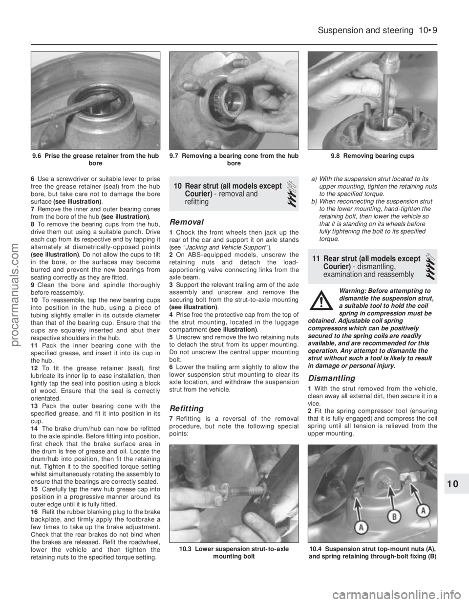
6Use a screwdriver or suitable lever to prise
free the grease retainer (seal) from the hub
bore, but take care not to damage the bore
surface (see illustration) .
7 Remove the inner and outer bearing cones
from the bore of the hub (see illustration).
8 To remove the bearing cups from the hub,
drive them out using a suitable punch. Drive
each cup from its respective end by tapping it
alternately at diametrically-opposed points
(see illustration) . Do not allow the cups to tilt
in the bore, or the surfaces may become
burred and prevent the new bearings from
seating correctly as they are fitted.
9 Clean the bore and spindle thoroughly
before reassembly.
10 To reassemble, tap the new bearing cups
into position in the hub, using a piece of
tubing slightly smaller in its outside diameter
than that of the bearing cup. Ensure that the
cups are squarely inserted and abut their
respective shoulders in the hub.
11 Pack the inner bearing cone with the
specified grease, and insert it into its cup in
the hub.
12 To fit the grease retainer (seal), first
lubricate its inner lip to ease installation, then
lightly tap the seal into position using a block
of wood. Ensure that the seal is correctly
orientated.
13 Pack the outer bearing cone with the
specified grease, and fit it into position in its
cup.
14 The brake drum/hub can now be refitted
to the axle spindle. Before fitting into position,
first check that the brake surface area in
the drum is free of grease and oil. Locate the
drum/hub into position, then fit the retaining
nut. Tighten it to the specified torque setting
whilst simultaneously rotating the assembly to
ensure that the bearings are correctly seated.
15 Carefully tap the new hub grease cap into
position in a progressive manner around its
outer edge until it is fully fitted.
16 Refit the rubber blanking plug to the brake
backplate, and firmly apply the footbrake a
few times to take up the brake adjustment.
Check that the rear brakes do not bind when
the brakes are released. Refit the roadwheel,
lower the vehicle and then tighten the
retaining nuts to the specified torque setting.10 Rear strut (all models except Courier) - removal and
refitting
3
Removal
1 Chock the front wheels then jack up the
rear of the car and support it on axle stands
(see “Jacking and Vehicle Support” ).
2 On ABS-equipped models, unscrew the
retaining nuts and detach the load-
apportioning valve connecting links from the
axle beam.
3 Support the relevant trailing arm of the axle
assembly and unscrew and remove the
securing bolt from the strut-to-axle mounting
(see illustration) .
4 Prise free the protective cap from the top of
the strut mounting, located in the luggage
compartment (see illustration) .
5 Unscrew and remove the two retaining nuts
to detach the strut from its upper mounting.
Do not unscrew the central upper mounting
bolt.
6 Lower the trailing arm slightly to allow the
lower suspension strut mounting to clear its
axle location, and withdraw the suspension
strut from the vehicle.
Refitting
7 Refitting is a reversal of the removal
procedure, but note the following special
points: a)
With the suspension strut located to its
upper mounting, tighten the retaining nuts
to the specified torque.
b) When reconnecting the suspension strut
to the lower mounting, hand-tighten the
retaining bolt, then lower the vehicle so
that it is standing on its wheels before
fully tightening the bolt to its specified
torque.
11 Rear strut (all models except
Courier) - dismantling,
examination and reassembly
4
Warning: Before attempting to
dismantle the suspension strut,
a suitable tool to hold the coil
spring in compression must be
obtained. Adjustable coil spring
compressors which can be positively
secured to the spring coils are readily
available, and are recommended for this
operation. Any attempt to dismantle the
strut without such a tool is likely to result
in damage or personal injury.
Dismantling
1 With the strut removed from the vehicle,
clean away all external dirt, then secure it in a
vice.
2 Fit the spring compressor tool (ensuring
that it is fully engaged) and compress the coil
spring until all tension is relieved from the
upper mounting.
Suspension and steering 10•9
9.8 Removing bearing cups9.7 Removing a bearing cone from the hub bore9.6 Prise the grease retainer from the hubbore
10.4 Suspension strut top-mount nuts (A),
and spring retaining through-bolt fixing (B)10.3 Lower suspension strut-to-axle mounting bolt
10
1595Ford Fiesta Remakeprocarmanuals.com
http://vnx.su
Page 203 of 296
3Unscrew and remove the upper mounting
through-bolt and nut.
4 Withdraw the upper mounting cup and the
spring seat.
5 The suspension strut and coil spring can now
be separated. If the coil spring or strut is to be
renewed, the original coil spring must be
released from the compressor. If it is to be re-
used, the coil spring can be left in compression.
Examination
6 With the strut assembly now completely
dismantled, examine the mounting
components for wear, damage or deformation.
Renew any of the components as necessary.
7 Examine the strut for signs of fluid leakage.
Check the strut piston for signs of pitting
along its entire length, and check the strut
body for signs of damage or deterioration of
the mountings. Test the operation of the strut,
holding it in an upright position, by moving the
piston through a full stroke, and then through
short strokes of 50 to 100 mm. In both cases,
the resistance felt should be smooth and
continuous. If the resistance is jerky, or
uneven, or if there is any visible sign of wear
or damage to the strut, renewal is necessary.
Reassembly
8 Reassembly is a reversal of the dismantling
procedure but note the following points: a) When the spring is located over the
suspension strut, the spring seat, cup and
through-bolt fitted, tighten the retaining
bolt to the specified torque.
b) When reassembled, check that the upper
and lower spring tails are correctly
engaged with their spring seats before
removing the spring compressor.
12 Rear axle (all models except
Courier) -
removal and refitting
3
Removal
1 Chock the front wheels then jack up the
rear of the car and support it on axle stands
(see “Jacking and Vehicle Support” ). Remove
the rear roadwheels.
2 Refer to Chapter 9 for details, and disconnect
the handbrake cable equaliser from the primary
cable. Remove the handbrake rear cable from
its adjuster and its fixed body locations.
3 Disconnect the rear brake flexible hydraulic
brake hoses from their rigid line connections.
Clamp the hoses before disconnecting them,
to minimise the fluid loss and air entry into the
hydraulic system (see Chapter 9 for details).
4 On ABS-equipped models, undo the
retaining nuts and detach the ABS load-
apportioning valve operating links from the
axle beam. Do not remove the load-
apportioning valve (see Chapter 9).
5 Locate suitable jacks or axle stands under
the axle beam to support its weight (not to lift
it), then unscrew the four mounting bracket
bolts each side. 6
Unscrew and remove the strut-to-axle
mounting bolt each side.
7 Check that all associated fittings are clear,
then lower the axle and remove it from under
the vehicle.
8 If the twist beam axle has been damaged, it
must be renewed. Refer to Chapter 9 for
details on removing the rear brakes from the
axle. To remove the front mounting/pivot
brackets from the axle, unscrew the pivot bolt.
Refitting
9 Refitting is a reversal of the removal
procedure, but note the following: a) Reconnect the axle at the front floor mountings first, and tighten the retaining
bolts to the specified torque.
b) Reconnect the axle to the suspension struts, but do not fully retighten the securing
bolts until after the vehicle is lowered to the
ground and is standing on its wheels.
c) Ensure that all brake fluid line connections are clean before reconnecting them. Refer
to the appropriate Sections in Chapter 9
for specific details on reconnecting the
brake lines, bleeding the brake hydraulic
system, and for reconnecting the
handbrake cable and its adjustment.
d) When the vehicle is lowered and is standing
on its wheels, tighten the suspension
fastenings to their specified torque settings.
13 Rear axle pivot bushes (all
models except Courier) -
renewal
3
Note: Two different types of pivot bushes
have been fitted during the course of Fiesta
production. It is understood that once stocks
of the early type are exhausted, only the latter
type will be supplied by Ford parts dealers. If
renewing pivot bushes on a pre-April 1990
model, and only the later type bushes are
available, fit the new bushes as described
from paragraph 15 onward.
Pre-April 1990 models
1 Chock the front wheels then jack up the
rear of the car and support it on axle stands
(see “Jacking and Vehicle Support” ).2
Position a suitable support (preferably
adjustable) under the axle twist beam so that
it is capable of carrying the weight of the axle
(not the weight of the vehicle).
3 On ABS-equipped models, undo the
retaining nuts and detach the ABS load-
apportioning valve operating links from the
axle beam. Do not remove the load-
apportioning valve (see Chapter 9).
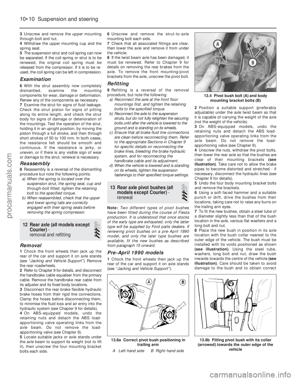
4 Unscrew the nuts, withdraw the pivot bolts,
then lower the rear axle so that the bushes are
clear of their mounting brackets (see
illustration) . Take care not to allow the brake
pipes to become distorted and stretched - if
necessary, disconnect the hydraulic lines (see
Chapter 9 for details).
5 Undo the four body mounting bracket bolts
and remove the brackets.
6 Using a soft-faced hammer and a suitable
punch or drift, drive the bushes from their
locations, taking care not to raise any burrs on
the trailing arm eyes.
7 To fit the new bushes, obtain a steel tube of
a diameter slightly less than that of the bush
location in the axle, various flat washers and a
long bolt and nut.
8 Place the new bush in position in its axle
location with the bush collar nearest to the
outer edge of the vehicle. The bush must be
installed with its voids positioned as shown
(see illustration) . Using the steel tube,
washers, long bolt and nut, draw the bush
inwards towards the centre of the vehicle (see
illustration) . Care should be taken to avoid
damage to the bush and to obtain correct
10•10 Suspension and steering
13.8b Fitting pivot bush with its collar
(arrowed) towards the outer edge of the vehicle13.8a Correct pivot bush positioning intrailing arm
A Left-hand side B Right-hand side
13.4 Pivot bush bolt (A) and body mounting bracket bolts (B)
1595Ford Fiesta Remakeprocarmanuals.com
http://vnx.su
Page 205 of 296
mountings for signs of wear. Test the
operation of the unit, holding it in an upright
position, by moving the piston through a full
stroke, and then through short strokes of 50
to 100 mm. In both cases, the resistance felt
should be smooth and continuous. If the
resistance is jerky, or uneven, or if there is any
visible sign of wear or damage, the shock
absorber should be renewed. Note that if
either unit is to be renewed, it is good practice
to renew both together as a matched pair.
Refitting
4Locate the unit in position and refit the
mounting bolts and nut. Do not fully tighten
the mountings at this stage.
5 Lower the vehicle to the ground and rock it
to settle the suspension. Raise the vehicle
again, as necessary, until the shock absorber
is at an angle of 50° ± 5° to the horizontal.
With the shock absorber in this position,
tighten the upper and lower mountings to the
specified torque.
17 Rear suspension assembly (Courier models) -
removal and refitting
3
Removal
1 Chock the front wheels then jack up the
rear of the car and support it on axle stands
(see “Jacking and Vehicle Support” ). Remove
the rear roadwheels.
2 Refer to Chapter 9 for details, and
disconnect the handbrake cable equaliser
from the primary cable. Remove the
handbrake rear cable from its adjuster and its
fixed body locations. Release the exhaust
system mountings as necessary to allow the
handbrake cable to be withdrawn over the
rear of the exhaust.
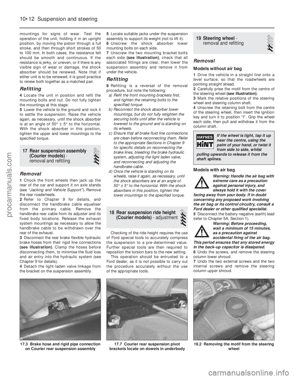
3 Disconnect the rear brake flexible hydraulic
brake hoses from their rigid line connections
(see illustration) . Clamp the hoses before
disconnecting them, to minimise the fluid loss
and air entry into the hydraulic system (see
Chapter 9 for details).
4 Detach the light-laden valve linkage from
the bracket on the suspension assembly. 5
Locate suitable jacks under the suspension
assembly to support its weight (not to lift it).
6 Unscrew the shock absorber lower
mounting bolts on each side.
7 Unscrew the two mounting bracket bolts
each side (see illustration) , check that all
associated fittings are clear, then lower the
suspension assembly and remove it from
under the vehicle.
Refitting
8 Refitting is a reversal of the removal
procedure, but note the following: a) Refit the front mounting brackets first,
and tighten the retaining bolts to the
specified torque.
b) Reconnect the shock absorber lower
mountings, but do not fully retighten the
securing bolts until after the vehicle is
lowered to the ground and is standing on
its wheels.
c) Ensure that all brake fluid line connections are clean before reconnecting them. Refer
to the appropriate Sections in Chapter 9
for specific details on reconnecting the
brake lines, bleeding the brake hydraulic
system, adjusting the light laden valve,
and reconnecting and adjusting the
handbrake cable.
d) Once the vehicle is standing on its
wheels, raise it again, as necessary, until
the shock absorbers are at an angle of
50° ± 5° to the horizontal. With the shock
absorbers in this position, tighten the
lower mountings to the specified torque.
18 Rear suspension ride height (Courier models) - adjustment
4
Checking of the ride height requires the use
of Ford special tools to accurately compress
the suspension to a pre-determined value.
Further special tools are then required to
reposition the torsion bars to the new setting.
This operation should be entrusted to a
Ford dealer, as it is not possible to carry out
the procedure accurately without the use
of the appropriate tools.
19 Steering wheel -
removal and refitting
2
Removal
Models without air bag
1 Drive the vehicle in a straight line onto a
level surface, so that the roadwheels are
pointing straight ahead.
2 Carefully prise the motif from the centre of
the steering wheel (see illustration).
3 Mark the relative positions of the steering
wheel and steering column shaft.
4 Unscrew the retaining bolt from the centre
of the steering wheel, then insert the ignition
key and turn it to position “I”. Grip the wheel
each side, then pull and withdraw it from the
column shaft.
Models with air bag
Warning: Handle the air bag with
extreme care as a precaution
against personal injury, and
always hold it with the cover
facing away from your body. If in doubt
concerning any proposed work involving
the air bag or its control circuitry, consult a
Ford dealer or other qualified specialist.
5 Disconnect the battery negative (earth) lead
(refer to Chapter 5A, Section 1).
Warning: Before proceeding,
wait a minimum of 15 minutes,
as a precaution against
accidental firing of the air bag.
This period ensures that any stored energy
in the back-up capacitor is dissipated.
6 Undo the screws, and remove the steering
column lower shroud.
7 Undo the two external screws and the two
internal screws and remove the steering
column upper shroud.
10•12 Suspension and steering
19.2 Removing the motif from the steering wheel17.7 Courier rear suspension pivot
brackets locate on dowels in underbody17.3 Brake hose and rigid pipe connection on Courier rear suspension assembly
1595Ford Fiesta Remake
If the wheel is tight, tap it up
near the centre, using the
palm of your hand, or twist it
from side to side, whilst
pulling upwards to release it from the
shaft splines.
procarmanuals.com
http://vnx.su
Page 211 of 296
Front wheel toe setting -
checking and adjustment
2Due to the special measuring equipment
necessary to accurately check the wheel
alignment, and the skill required to use it
properly, checking and adjustment is best left
to a Ford dealer or similar expert. Note that
most tyre-fitting shops now possess
sophisticated checking equipment. The
following is provided as a guide, should the
owner decide to carry out a DIY check.
3 The front wheel toe setting is checked by
measuring the distance between the front and
rear inside edges of the roadwheel rims.
Proprietary toe measurement gauges are
available from motor accessory shops.
Adjustment is made by screwing the track
rods in or out of their track rod end balljoints,
to alter the effective length of the track rod
assemblies.
4 For accurate checking, the vehicle must
be at the kerb weight, ie unladen and with a
full tank of fuel.
5 Before starting work, check the tyre
pressures and tread wear, the condition of the
hub bearings, the steering wheel free play,
and the condition of the front suspension
components (see Chapter 1). Correct any
faults found.
6 Park the vehicle on level ground, check that
the front roadwheels are in the straight-ahead
position, then rock the rear and front ends to settle the suspension. Release the handbrake,
and roll the vehicle backwards 1 metre, then
forwards again, to relieve any stresses in the
steering and suspension components.
7
Measure the distance between the front
edges of the wheel rims and the rear edges of
the rims. Subtract the smallest measurement
from the largest, and check that the result is
within the specified range.
8 If adjustment is necessary, apply the
handbrake, then jack up the front of the
vehicle and support it securely on axle stands
(see “Jacking and Vehicle Support” ). Turn the
steering wheel onto full-left lock, and record
the number of exposed threads on the right-
hand track rod. Now turn the steering onto
full-right lock, and record the number of
threads on the left-hand side. If there are the
same number of threads visible on both sides,
then subsequent adjustment should be made
equally on both sides. If there are more
threads visible on one side than the other, it
will be necessary to compensate for this
during adjustment. Note:It is most important
that after adjustment, the same number of
threads are visible on each track rod.
9 First clean the track rod end; if they are
corroded, apply penetrating fluid before
starting adjustment. Release the rubber gaiter
outboard clips (where necessary), and peel
back the gaiter; apply a smear of grease to
the inside of the gaiter, so that both are free, and will not be twisted or strained as their
respective track rods are rotated.
10
Use a straight-edge and a scriber or
similar to mark the relationship of each track
rod to its track rod end balljoint, then, holding
each track rod in turn, unscrew its locknut
fully.
11 Alter the length of the track rods, bearing
in mind the note made in paragraph 8. Screw
them into or out of the track rod end balljoints,
rotating the track rods using a self-grip
wrench. Shortening the track rods (screwing
them into their track rod end balljoints) will
reduce toe-in/increase toe-out.
12 When the setting is correct, hold the track
rods and securely tighten the track rod end
balljoint locknuts. Count the exposed threads
to check the length of both track rods. If they
are not the same, then the adjustment has not
been made equally, and problems will be
encountered with tyre scrubbing in turns;
also, the steering wheel spokes will no longer
be horizontal when the wheels are in the
straight-ahead position.
13 If the track rod lengths are the same, lower
the vehicle to the ground and re-check the
toe setting; re-adjust if necessary. When the
setting is correct, securely tighten the track rod
end balljoint locknuts. Ensure that the rubber
gaiters are seated correctly, and are not
twisted or strained, and secure them in position
with new retaining clips (where necessary).
10•18 Suspension and steering
1595Ford Fiesta Remakeprocarmanuals.com
http://vnx.su