1989 FORD FIESTA reset
[x] Cancel search: resetPage 194 of 296
10
1595Ford Fiesta Remake
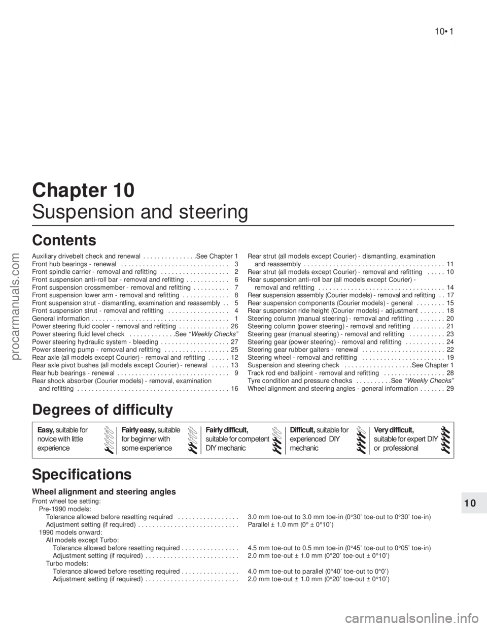
Wheel alignment and steering angles
Front wheel toe setting:Pre-1990 models: Tolerance allowed before resetting required . . . . . . . . . . . . . . . . . 3.0 mm toe-out to 3.0 mm toe-in (0°30’ toe-out to 0°30’ toe-in)
Adjustment setting (if required) . . . . . . . . . . . . . . . . . . . . . . . . . . . . Parallel ± 1.0 mm (0° ± 0°10’)
1990 models onward: All models except Turbo:
Tolerance allowed before resetting required . . . . . . . . . . . . . . \
. . 4.5 mm toe-out to 0.5 mm toe-in (0°45’ toe-out to 0°05’ toe-in)
Adjustment setting (if required) . . . . . . . . . . . . . . . . . . . . . . . . . . 2.0 mm toe-out ± 1.0 mm (0°20’ toe-out ± 0°10’)
Turbo models:
Tolerance allowed before resetting required . . . . . . . . . . . . . . \
. . 4.0 mm toe-out to parallel (0°40’ toe-out to 0°0’)
Adjustment setting (if required) . . . . . . . . . . . . . . . . . . . . . . . . . . 2.0 mm toe-out ± 1.0 mm (0°20’ toe-out ± 0°10’)
Chapter 10
Suspension and steering
Auxiliary drivebelt check and renewal . . . . . . . . . . . . . . .See Chapter 1
Front hub bearings - renewal . . . . . . . . . . . . . . . . . . . . . . . . . . . . . . 3
Front spindle carrier - removal and refitting . . . . . . . . . . . . . . . . . . . 2
Front suspension anti-roll bar - removal and refitting . . . . . . . . . . . . 6
Front suspension crossmember - removal and refitting . . . . . . . . . . 7
Front suspension lower arm - removal and refitting . . . . . . . . . . . . . 8
Front suspension strut - dismantling, examination and reassembly . . 5
Front suspension strut - removal and refitting . . . . . . . . . . . . . . . . . 4
General information . . . . . . . . . . . . . . . . . . . . . . . . . . . . . . . . . . . .\
. . 1
Power steering fluid cooler - removal and refitting . . . . . . . . . . . . . . 26
Power steering fluid level check . . . . . . . . . . . . .See
“Weekly Checks”
Power steering hydraulic system - bleeding . . . . . . . . . . . . . . . . . . . 27
Power steering pump - removal and refitting . . . . . . . . . . . . . . . . . . 25
Rear axle (all models except Courier) - removal and refitting . . . . . . 12
Rear axle pivot bushes (all models except Courier) - renewal . . . . . 13
Rear hub bearings - renewal . . . . . . . . . . . . . . . . . . . . . . . . . . . . . . . 9
Rear shock absorber (Courier models) - removal, examination and refitting . . . . . . . . . . . . . . . . . . . . . . . . . . . . . . . . . . . .\
. . . . . . 16 Rear strut (all models except Courier) - dismantling, examination
and reassembly . . . . . . . . . . . . . . . . . . . . . . . . . . . . . . . . . . . .\
. . . 11
Rear strut (all models except Courier) - removal and refitting . . . . . 10
Rear suspension anti-roll bar (all models except Courier) - removal and refitting . . . . . . . . . . . . . . . . . . . . . . . . . . . . . . . . . . . 14
Rear suspension assembly (Courier models) - removal and refitting . . 17
Rear suspension components (Courier models) - general . . . . . . . . 15
Rear suspension ride height (Courier models) - adjustment . . . . . . . 18
Steering column (manual steering) - removal and refitting . . . . . . . . 20
Steering column (power steering) - removal and refitting . . . . . . . . . 21
Steering gear (manual steering) - removal and refitting . . . . . . . . . . 23
Steering gear (power steering) - removal and refitting . . . . . . . . . . . 24
Steering gear rubber gaiters - renewal . . . . . . . . . . . . . . . . . . . . . . . 22
Steering wheel - removal and refitting . . . . . . . . . . . . . . . . . . . . . . . 19
Suspension and steering check . . . . . . . . . . . . . . . . . . .See Chapter 1
Track rod end balljoint - removal and refitting . . . . . . . . . . . . . . . . . 28
Tyre condition and pressure checks . . . . . . . . . .See “Weekly Checks”
Wheel alignment and steering angles - general information . . . . . . . 29
10•1
Specifications Contents
Easy, suitable for
novice with little
experience Fairly easy,
suitable
for beginner with
some experience Fairly difficult,
suitable for competent
DIY mechanic
Difficult,
suitable for
experienced DIY
mechanic Very difficult,
suitable for expert DIY
or professional
Degrees of difficulty
54321
procarmanuals.com
http://vnx.su
Page 208 of 296
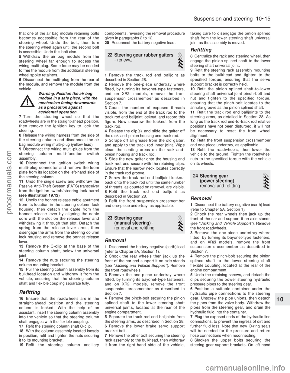
that one of the air bag module retaining bolts
becomes accessible from the rear of the
steering wheel. Undo the bolt, then turn
the steering wheel again until the second bolt
is accessible. Undo this bolt also.
5Withdraw the air bag module from the
steering wheel far enough to access the
wiring multi-plug. Some force may be needed
to free the module from the additional steering
wheel spoke retainers.
6 Disconnect the multi-plug from the rear of
the module, and remove the module from the
vehicle. Warning: Position the air bag
module in a safe place, with the
mechanism facing downwards
as a precaution against
accidental operation.
7 Turn the steering wheel so that the
roadwheels are in the straight-ahead position,
then remove the ignition key to lock the
steering.
8 Release the wiring harness from the side of
the steering column and disconnect the air
bag module wiring multi-plug (yellow lead).
9 Disconnect the wiring multi-plugs from the
steering column multi-function switch
assembly.
10 Disconnect the ignition switch wiring
multi-plug connector and remove the loom
plate from its location on the left-hand side of
the steering column.
11 Undo the single screw and withdraw the
Passive Anti-Theft System (PATS) transceiver
from the ignition switch/steering lock barrel
(see illustration 19.12) .
12 Unclip the bonnet release cable abutment
from its location in the steering column lock
housing, then detach the cable from the
bonnet release lever by aligning the cable
core with the slot on the release lever and
withdrawing it through that slot. Detach the
spring from the release lever arms, then
disengage the arms from the steering column
lock housing and remove the bonnet release
lever.
13 Remove the C-clip at the base of the
steering column shaft, below the universal
joint.
14 Remove the nuts securing the steering
column mounting bracket.
15 Pull the steering column assembly from its
bulkhead location and withdraw it from the
vehicle, ensuring that the steering column
shaft and flexible coupling separate fully.
Refitting
16 Ensure that the roadwheels are in the
straight-ahead position and the steering
column is locked. With the help of an
assistant, insert the steering column assembly
into the vehicle so that the steering column
shaft engages with the flexible coupling.
17 Refit the steering column shaft C-clip.
18 With the column assembly located loosely
in position, refit and tighten the nuts securing
it to its mounting bracket.
19 Refit the steering column ancillary components, reversing the removal procedure
given in paragraphs 2 to 12.
20
Reconnect the battery negative lead.
22 Steering gear rubber gaiters
- renewal
3
1Remove the track rod end balljoint as
described in Section 28.
2 Remove the one-piece undertray where
fitted, by turning its bayonet-type fasteners,
and on XR2i models, remove the front
suspension crossmember as described in
Section 7.
3 Count the number of exposed threads
visible, from the end of the track rod to the
track rod end balljoint locknut, and record this
figure. Now unscrew the locknut from the
track rod.
4 Release the clip(s), and slide the gaiter off
the rack-and-pinion housing and track rod.
5 Scrape off all grease from the old gaiter,
and apply to the track rod inner joint. Wipe
clean the seating areas on the rack-and-
pinion housing and track rod.
6 Slide the new gaiter onto the housing and
track rod, and secure with the retaining clips.
Ensure that the narrow neck locates correctly
in the track rod groove.
7 Screw the track rod end balljoint locknut
back onto the track rod until the same number
of threads, as counted on removal, are visible.
8 Refit the track rod end balljoint as
described in Section 28.
9 Refit the front suspension crossmember
and one-piece undertray, as applicable.
23 Steering gear (manual steering) -
removal and refitting
3
Removal
1 Disconnect the battery negative (earth) lead
(refer to Chapter 5A, Section 1).
2 Chock the rear wheels then jack up the
front of the car and support it on axle stands
(see “Jacking and Vehicle Support” ). Remove
the front roadwheels.
3 Remove the one-piece undertray where
fitted, by turning its bayonet-type fasteners,
and on XR2i models, remove the front
suspension crossmember as described in
Section 7.
4 Remove the pinch-bolt securing the pinion
splined shaft to the lower steering shaft
universal joints, located at the rear of the
engine compartment.
5 Separate the track rod end balljoints from
the steering arms, as described in Section 28.
6 Remove the lower brake servo support
bracket bolt.
7 Remove the other bolt securing the steering
rack assembly to the bulkhead, then withdraw
it from the right-hand side of the vehicle, taking care to disengage the pinion splined
shaft from the lower steering shaft universal
joint as the assembly is moved.
Refitting
8
Centralize the rack and steering wheel, then
engage the pinion splined shaft to the lower
steering shaft universal joint.
9 Refit the steering rack assembly mounting
bolts to the bulkhead and tighten to the
specified torque, ensuring that the servo
support bracket is correctly held.
10 Refit the pinion splined shaft-to-lower
steering shaft universal joint pinch-bolt and
nut and tighten to the specified torque,
ensuring that the pinch-bolt locates to the
annular groove as the pinion splined shaft.
11 Refit the track rod end balljoints to the
steering arms, as detailed in Section 28. As
long as the track rod end-to-track rod relative
positions have not been disturbed, it will not
be necessary to reset the front wheel
alignment.
12 Refit the front suspension crossmember
and one-piece undertray, as applicable.
13 Refit the roadwheels, then lower the
vehicle to the ground. Tighten the roadwheel
nuts to the specified torque with the vehicle
on its wheels.
24 Steering gear (power steering) -
removal and refitting
4
Removal
1 Disconnect the battery negative (earth) lead
(refer to Chapter 5A, Section 1).
2 Chock the rear wheels then jack up the
front of the car and support it on axle stands
(see “Jacking and Vehicle Support” ). Remove
the front roadwheels.
3 Remove the one-piece undertray where
fitted, by turning its bayonet-type fasteners,
and on XR2i models, remove the front
suspension crossmember as described in
Section 7.
4 Remove the pinch-bolt securing the pinion
splined shaft to the lower steering shaft
flexible coupling, located at the rear of the
engine compartment.
5 Undo the retaining screws, and detach the
clips securing the power steering hydraulic
pressure pipes to the steering gear.
6 Position a suitable container under the
hydraulic pipe connections to the steering
gear. Unscrew the pipe unions, then detach
the pipes from the valve body. Withdraw the
pipes from the steering gear, and drain the
hydraulic fluid into the container.
7 Plug the exposed ends of the hydraulic line
connections, to prevent the ingress of dirt and
further fluid loss. Note that new O-ring seals
will be needed for the pressure and return
hose connections when reconnecting.
8 Slacken the upper bolts securing the
steering gear support brackets. On left-hand
Suspension and steering 10•15
10
1595Ford Fiesta Remakeprocarmanuals.com
http://vnx.su
Page 209 of 296
drive models, remove the brace from the stud
on the left-hand side of the steering gear.
9Undo the two bolts securing the support
brackets to the steering gear and move the
brackets and swing the brackets clear.
10 Unhook the steering gear from the
apertures in the bulkhead and remove the
assembly from the right-hand wheel arch.
Ensure that the pressure check valve does not
fall out of the pressure port in the valve body
as the steering gear is removed.
Refitting
11 Centralize the steering gear and steering
wheel, then engage the pinion splined shaft to
the lower steering shaft flexible coupling.
12 Hook the steering gear into the apertures
in the bulkhead then align the support
brackets and refit the two bolts. Tighten the
support bracket upper bolts and support
bracket-to-steering gear bolts to the specified
torque.
13 On left-hand drive models, refit the brace
to the stud on the left-hand side of the
steering gear.
14 Fit new O-ring seals to the pressure and
return hoses, then reconnect the hydraulic
lines to the steering gear. Secure the pipes
with the retaining clips.
15 Refit the pinion splined shaft-to-lower
steering shaft flexible coupling pinch-bolt and
nut and tighten to the specified torque.
16 Refit the track rod end balljoints to the
steering arms, as detailed in Section 28. As
long as the track rod end-to-track rod relative
positions have not been disturbed, it will not
be necessary to reset the front wheel
alignment.
17 Refit the front suspension crossmember
and one-piece undertray, as applicable.
18 Refit the roadwheels, then lower the
vehicle to the ground. Tighten the roadwheel
nuts with the vehicle on its wheels to the
specified torque.
19 On completion, bleed the power steering
hydraulic system as described in Section 27.
Check for any signs of fluid leakage from the
system hoses and connections.
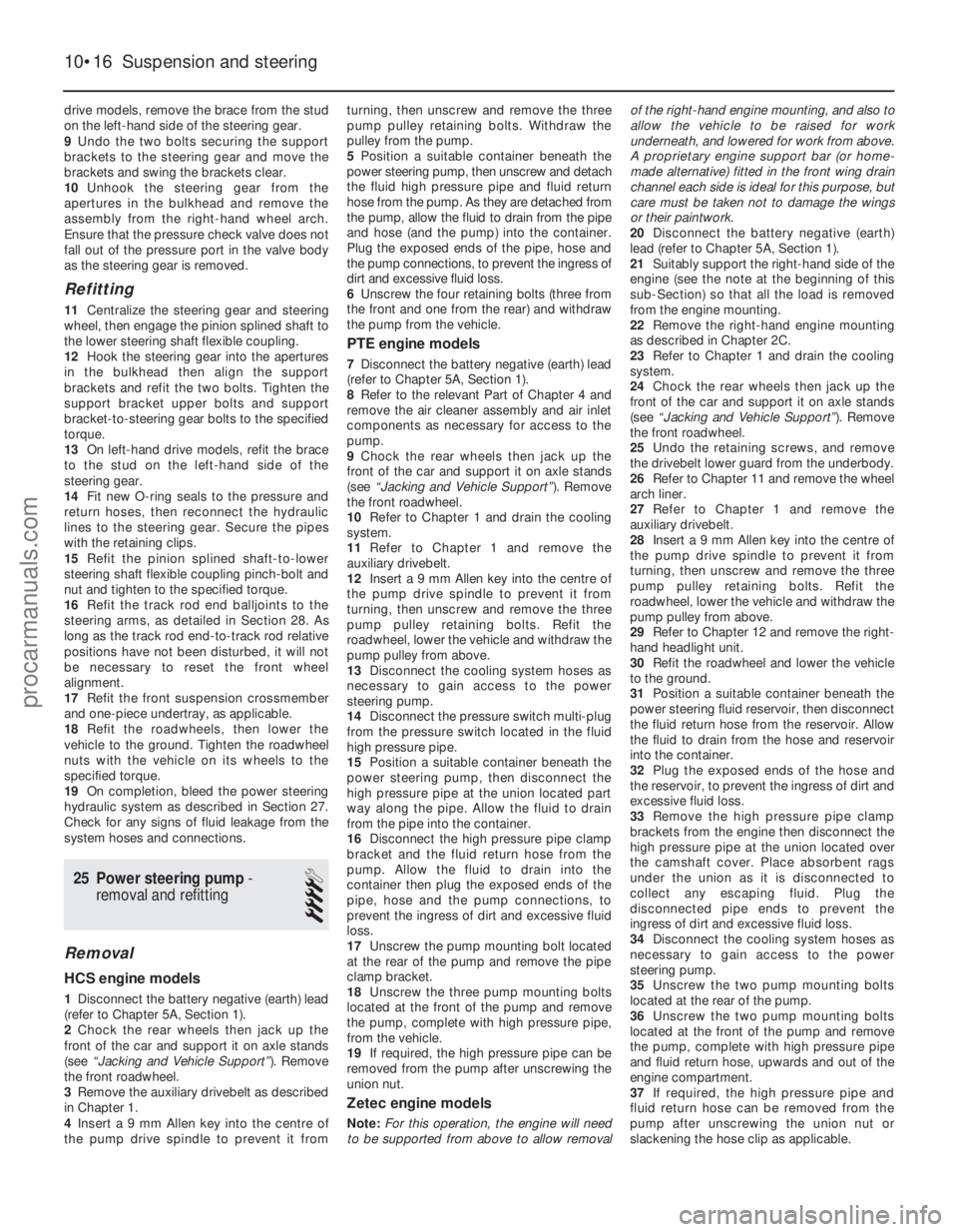
25 Power steering pump -
removal and refitting
4
Removal
HCS engine models
1 Disconnect the battery negative (earth) lead
(refer to Chapter 5A, Section 1).
2 Chock the rear wheels then jack up the
front of the car and support it on axle stands
(see “Jacking and Vehicle Support” ). Remove
the front roadwheel.
3 Remove the auxiliary drivebelt as described
in Chapter 1.
4 Insert a 9 mm Allen key into the centre of
the pump drive spindle to prevent it from turning, then unscrew and remove the three
pump pulley retaining bolts. Withdraw the
pulley from the pump.
5
Position a suitable container beneath the
power steering pump, then unscrew and detach
the fluid high pressure pipe and fluid return
hose from the pump. As they are detached from
the pump, allow the fluid to drain from the pipe
and hose (and the pump) into the container.
Plug the exposed ends of the pipe, hose and
the pump connections, to prevent the ingress of
dirt and excessive fluid loss.
6 Unscrew the four retaining bolts (three from
the front and one from the rear) and withdraw
the pump from the vehicle.
PTE engine models
7 Disconnect the battery negative (earth) lead
(refer to Chapter 5A, Section 1).
8 Refer to the relevant Part of Chapter 4 and
remove the air cleaner assembly and air inlet
components as necessary for access to the
pump.
9 Chock the rear wheels then jack up the
front of the car and support it on axle stands
(see “Jacking and Vehicle Support” ). Remove
the front roadwheel.
10 Refer to Chapter 1 and drain the cooling
system.
11 Refer to Chapter 1 and remove the
auxiliary drivebelt.
12 Insert a 9 mm Allen key into the centre of
the pump drive spindle to prevent it from
turning, then unscrew and remove the three
pump pulley retaining bolts. Refit the
roadwheel, lower the vehicle and withdraw the
pump pulley from above.
13 Disconnect the cooling system hoses as
necessary to gain access to the power
steering pump.
14 Disconnect the pressure switch multi-plug
from the pressure switch located in the fluid
high pressure pipe.
15 Position a suitable container beneath the
power steering pump, then disconnect the
high pressure pipe at the union located part
way along the pipe. Allow the fluid to drain
from the pipe into the container.
16 Disconnect the high pressure pipe clamp
bracket and the fluid return hose from the
pump. Allow the fluid to drain into the
container then plug the exposed ends of the
pipe, hose and the pump connections, to
prevent the ingress of dirt and excessive fluid
loss.
17 Unscrew the pump mounting bolt located
at the rear of the pump and remove the pipe
clamp bracket.
18 Unscrew the three pump mounting bolts
located at the front of the pump and remove
the pump, complete with high pressure pipe,
from the vehicle.
19 If required, the high pressure pipe can be
removed from the pump after unscrewing the
union nut.
Zetec engine models
Note: For this operation, the engine will need
to be supported from above to allow removal of the right-hand engine mounting, and also to
allow the vehicle to be raised for work
underneath, and lowered for work from above.
A proprietary engine support bar (or home-
made alternative) fitted in the front wing drain
channel each side is ideal for this purpose, but
care must be taken not to damage the wings
or their paintwork.
20
Disconnect the battery negative (earth)
lead (refer to Chapter 5A, Section 1).
21 Suitably support the right-hand side of the
engine (see the note at the beginning of this
sub-Section) so that all the load is removed
from the engine mounting.
22 Remove the right-hand engine mounting
as described in Chapter 2C.
23 Refer to Chapter 1 and drain the cooling
system.
24 Chock the rear wheels then jack up the
front of the car and support it on axle stands
(see “Jacking and Vehicle Support” ). Remove
the front roadwheel.
25 Undo the retaining screws, and remove
the drivebelt lower guard from the underbody.
26 Refer to Chapter 11 and remove the wheel
arch liner.
27 Refer to Chapter 1 and remove the
auxiliary drivebelt.
28 Insert a 9 mm Allen key into the centre of
the pump drive spindle to prevent it from
turning, then unscrew and remove the three
pump pulley retaining bolts. Refit the
roadwheel, lower the vehicle and withdraw the
pump pulley from above.
29 Refer to Chapter 12 and remove the right-
hand headlight unit.
30 Refit the roadwheel and lower the vehicle
to the ground.
31 Position a suitable container beneath the
power steering fluid reservoir, then disconnect
the fluid return hose from the reservoir. Allow
the fluid to drain from the hose and reservoir
into the container.
32 Plug the exposed ends of the hose and
the reservoir, to prevent the ingress of dirt and
excessive fluid loss.
33 Remove the high pressure pipe clamp
brackets from the engine then disconnect the
high pressure pipe at the union located over
the camshaft cover. Place absorbent rags
under the union as it is disconnected to
collect any escaping fluid. Plug the
disconnected pipe ends to prevent the
ingress of dirt and excessive fluid loss.
34 Disconnect the cooling system hoses as
necessary to gain access to the power
steering pump.
35 Unscrew the two pump mounting bolts
located at the rear of the pump.
36 Unscrew the two pump mounting bolts
located at the front of the pump and remove
the pump, complete with high pressure pipe
and fluid return hose, upwards and out of the
engine compartment.
37 If required, the high pressure pipe and
fluid return hose can be removed from the
pump after unscrewing the union nut or
slackening the hose clip as applicable.
10•16 Suspension and steering
1595Ford Fiesta Remakeprocarmanuals.com
http://vnx.su
Page 213 of 296
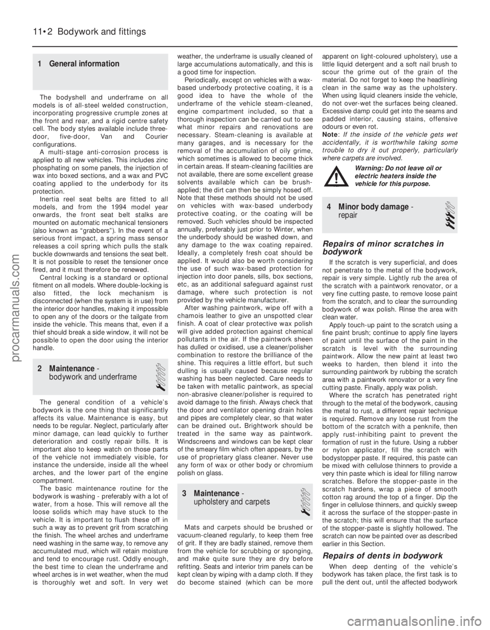
1 General information
The bodyshell and underframe on all
models is of all-steel welded construction,
incorporating progressive crumple zones at
the front and rear, and a rigid centre safety
cell. The body styles available include three-
door, five-door, Van and Courier
configurations. A multi-stage anti-corrosion process is
applied to all new vehicles. This includes zinc
phosphating on some panels, the injection of
wax into boxed sections, and a wax and PVC
coating applied to the underbody for its
protection. Inertia reel seat belts are fitted to all
models, and from the 1994 model year
onwards, the front seat belt stalks are
mounted on automatic mechanical tensioners
(also known as “grabbers”). In the event of a
serious front impact, a spring mass sensor
releases a coil spring which pulls the stalk
buckle downwards and tensions the seat belt.
It is not possible to reset the tensioner once
fired, and it must therefore be renewed. Central locking is a standard or optional
fitment on all models. Where double-locking is
also fitted, the lock mechanism is
disconnected (when the system is in use) from
the interior door handles, making it impossible
to open any of the doors or the tailgate from
inside the vehicle. This means that, even if a
thief should break a side window, it will not be
possible to open the door using the interior
handle.
2 Maintenance -
bodywork and underframe
1
The general condition of a vehicle’s
bodywork is the one thing that significantly
affects its value. Maintenance is easy, but
needs to be regular. Neglect, particularly after
minor damage, can lead quickly to further
deterioration and costly repair bills. It is
important also to keep watch on those parts
of the vehicle not immediately visible, for
instance the underside, inside all the wheel
arches, and the lower part of the engine
compartment. The basic maintenance routine for the
bodywork is washing - preferably with a lot of
water, from a hose. This will remove all the
loose solids which may have stuck to the
vehicle. It is important to flush these off in
such a way as to prevent grit from scratching
the finish. The wheel arches and underframe
need washing in the same way, to remove any
accumulated mud, which will retain moisture
and tend to encourage rust. Oddly enough,
the best time to clean the underframe and
wheel arches is in wet weather, when the mud
is thoroughly wet and soft. In very wet weather, the underframe is usually cleaned of
large accumulations automatically, and this is
a good time for inspection.
Periodically, except on vehicles with a wax-
based underbody protective coating, it is a
good idea to have the whole of the
underframe of the vehicle steam-cleaned,
engine compartment included, so that a
thorough inspection can be carried out to see
what minor repairs and renovations are
necessary. Steam-cleaning is available at
many garages, and is necessary for the
removal of the accumulation of oily grime,
which sometimes is allowed to become thick
in certain areas. If steam-cleaning facilities are
not available, there are some excellent grease
solvents available which can be brush-
applied; the dirt can then be simply hosed off.
Note that these methods should not be used
on vehicles with wax-based underbody
protective coating, or the coating will be
removed. Such vehicles should be inspected
annually, preferably just prior to Winter, when
the underbody should be washed down, and
any damage to the wax coating repaired.
Ideally, a completely fresh coat should be
applied. It would also be worth considering
the use of such wax-based protection for
injection into door panels, sills, box sections,
etc, as an additional safeguard against rust
damage, where such protection is not
provided by the vehicle manufacturer. After washing paintwork, wipe off with a
chamois leather to give an unspotted clear
finish. A coat of clear protective wax polish
will give added protection against chemical
pollutants in the air. If the paintwork sheen
has dulled or oxidised, use a cleaner/polisher
combination to restore the brilliance of the
shine. This requires a little effort, but such
dulling is usually caused because regular
washing has been neglected. Care needs to
be taken with metallic paintwork, as special
non-abrasive cleaner/polisher is required to
avoid damage to the finish. Always check that
the door and ventilator opening drain holes
and pipes are completely clear, so that water
can be drained out .Brightwork should be
treated in the same way as paintwork.
Windscreens and windows can be kept clear
of the smeary film which often appears, by the
use of proprietary glass cleaner. Never use
any form of wax or other body or chromium
polish on glass.
3 Maintenance -
upholstery and carpets
1
Mats and carpets should be brushed or
vacuum-cleaned regularly, to keep them free
of grit. If they are badly stained, remove them
from the vehicle for scrubbing or sponging,
and make quite sure they are dry before
refitting. Seats and interior trim panels can be
kept clean by wiping with a damp cloth. If they
do become stained (which can be more apparent on light-coloured upholstery), use a
little liquid detergent and a soft nail brush to
scour the grime out of the grain of the
material. Do not forget to keep the headlining
clean in the same way as the upholstery.
When using liquid cleaners inside the vehicle,
do not over-wet the surfaces being cleaned.
Excessive damp could get into the seams and
padded interior, causing stains, offensive
odours or even rot.
Note
:
If the inside of the vehicle gets wet
accidentally, it is worthwhile taking some
trouble to dry it out properly, particularly
where carpets are involved .
Warning: Do not leave oil or
electric heaters inside the
vehicle for this purpose.
4 Minor body damage-
repair
3
Repairs of minor scratches in
bodywork
If the scratch is very superficial, and does
not penetrate to the metal of the bodywork,
repair is very simple. Lightly rub the area of
the scratch with a paintwork renovator, or a
very fine cutting paste, to remove loose paint
from the scratch, and to clear the surrounding
bodywork of wax polish. Rinse the area with
clean water. Apply touch-up paint to the scratch using a
fine paint brush; continue to apply fine layers
of paint until the surface of the paint in the
scratch is level with the surrounding
paintwork. Allow the new paint at least two
weeks to harden, then blend it into the
surrounding paintwork by rubbing the scratch
area with a paintwork renovator or a very fine
cutting paste. Finally, apply wax polish. Where the scratch has penetrated right
through to the metal of the bodywork, causing
the metal to rust, a different repair technique
is required. Remove any loose rust from the
bottom of the scratch with a penknife, then
apply rust-inhibiting paint to prevent the
formation of rust in the future. Using a rubber
or nylon applicator, fill the scratch with
bodystopper paste. If required, this paste can
be mixed with cellulose thinners to provide a
very thin paste which is ideal for filling narrow
scratches. Before the stopper-paste in the
scratch hardens, wrap a piece of smooth
cotton rag around the top of a finger. Dip the
finger in cellulose thinners, and quickly sweep
it across the surface of the stopper-paste in
the scratch; this will ensure that the surface
of the stopper-paste is slightly hollowed. The
scratch can now be painted over as described
earlier in this Section.
Repairs of dents in bodywork
When deep denting of the vehicle’s
bodywork has taken place, the first task is to
pull the dent out, until the affected bodywork
11•2 Bodywork and fittings
1595Ford Fiesta Remakeprocarmanuals.com
http://vnx.su
Page 244 of 296
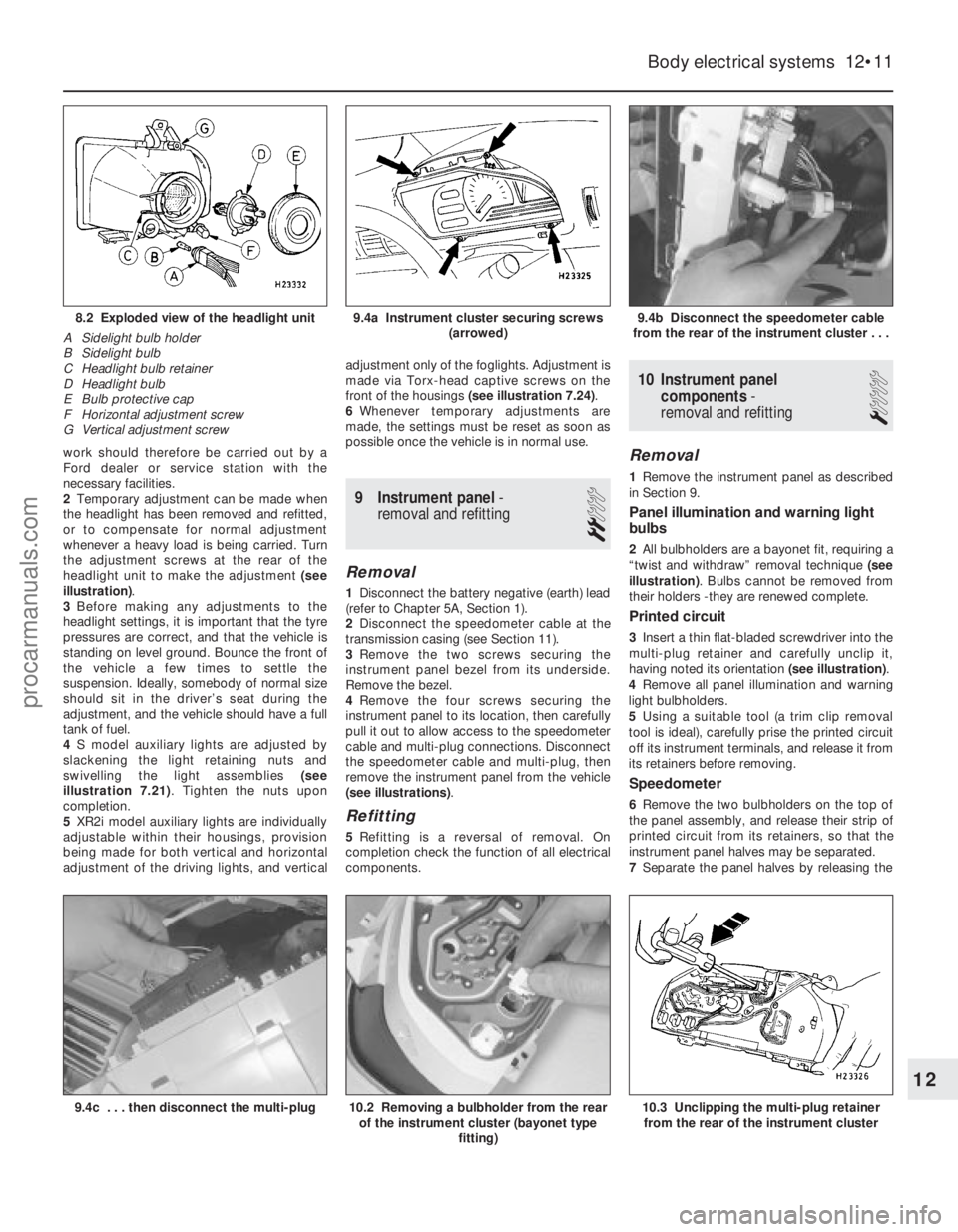
work should therefore be carried out by a
Ford dealer or service station with the
necessary facilities.
2Temporary adjustment can be made when
the headlight has been removed and refitted,
or to compensate for normal adjustment
whenever a heavy load is being carried. Turn
the adjustment screws at the rear of the
headlight unit to make the adjustment (see
illustration) .
3 Before making any adjustments to the
headlight settings, it is important that the tyre
pressures are correct, and that the vehicle is
standing on level ground. Bounce the front of
the vehicle a few times to settle the
suspension. Ideally, somebody of normal size
should sit in the driver’s seat during the
adjustment, and the vehicle should have a full
tank of fuel.
4 S model auxiliary lights are adjusted by
slackening the light retaining nuts and
swivelling the light assemblies (see
illustration 7.21) . Tighten the nuts upon
completion.
5 XR2i model auxiliary lights are individually
adjustable within their housings, provision
being made for both vertical and horizontal
adjustment of the driving lights, and vertical adjustment only of the foglights. Adjustment is
made via Torx-head captive screws on the
front of the housings
(see illustration 7.24) .
6 Whenever temporary adjustments are
made, the settings must be reset as soon as
possible once the vehicle is in normal use.
9 Instrument panel -
removal and refitting
2
Removal
1 Disconnect the battery negative (earth) lead
(refer to Chapter 5A, Section 1).
2 Disconnect the speedometer cable at the
transmission casing (see Section 11).
3 Remove the two screws securing the
instrument panel bezel from its underside.
Remove the bezel.
4 Remove the four screws securing the
instrument panel to its location, then carefully
pull it out to allow access to the speedometer
cable and multi-plug connections. Disconnect
the speedometer cable and multi-plug, then
remove the instrument panel from the vehicle
(see illustrations) .
Refitting
5Refitting is a reversal of removal. On
completion check the function of all electrical
components.
10 Instrument panel
components -
removal and refitting
1
Removal
1 Remove the instrument panel as described
in Section 9.
Panel illumination and warning light
bulbs
2 All bulbholders are a bayonet fit, requiring a
“twist and withdraw” removal technique (see
illustration) . Bulbs cannot be removed from
their holders -they are renewed complete.
Printed circuit
3 Insert a thin flat-bladed screwdriver into the
multi-plug retainer and carefully unclip it,
having noted its orientation (see illustration).
4 Remove all panel illumination and warning
light bulbholders.
5 Using a suitable tool (a trim clip removal
tool is ideal), carefully prise the printed circuit
off its instrument terminals, and release it from
its retainers before removing.
Speedometer
6 Remove the two bulbholders on the top of
the panel assembly, and release their strip of
printed circuit from its retainers, so that the
instrument panel halves may be separated.
7 Separate the panel halves by releasing the
Body electrical systems 12•11
9.4b Disconnect the speedometer cable
from the rear of the instrument cluster . . .9.4a Instrument cluster securing screws (arrowed)8.2 Exploded view of the headlight unit
A Sidelight bulb holder
B Sidelight bulb
C Headlight bulb retainer
D Headlight bulb
E Bulb protective cap
F Horizontal adjustment screw
G Vertical adjustment screw
10.3 Unclipping the multi-plug retainer from the rear of the instrument cluster10.2 Removing a bulbholder from the rear of the instrument cluster (bayonet type
fitting)9.4c . . . then disconnect the multi-plug
12
1595Ford Fiesta Remakeprocarmanuals.com
http://vnx.su
Page 245 of 296
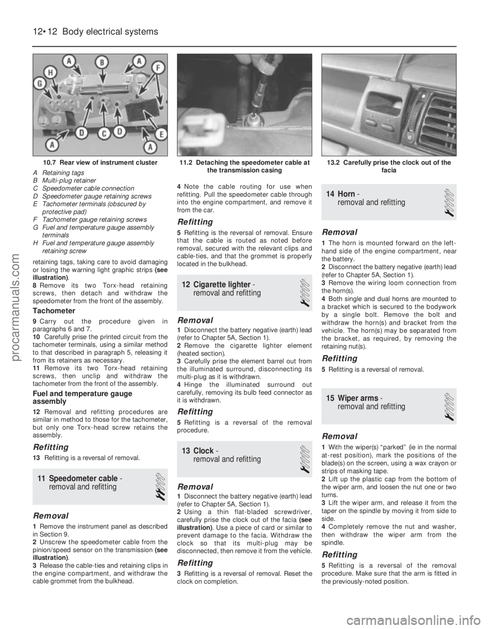
retaining tags, taking care to avoid damaging
or losing the warning light graphic strips (see
illustration) .
8 Remove its two Torx-head retaining
screws, then detach and withdraw the
speedometer from the front of the assembly.
Tachometer
9 Carry out the procedure given in
paragraphs 6 and 7.
10 Carefully prise the printed circuit from the
tachometer terminals, using a similar method
to that described in paragraph 5, releasing it
from its retainers as necessary.
11 Remove its two Torx-head retaining
screws, then unclip and withdraw the
tachometer from the front of the assembly.
Fuel and temperature gauge
assembly
12 Removal and refitting procedures are
similar in method to those for the tachometer,
but only one Torx-head screw retains the
assembly.
Refitting
13 Refitting is a reversal of removal.
11 Speedometer cable -
removal and refitting
2
Removal
1 Remove the instrument panel as described
in Section 9.
2 Unscrew the speedometer cable from the
pinion/speed sensor on the transmission (see
illustration) .
3 Release the cable-ties and retaining clips in
the engine compartment, and withdraw the
cable grommet from the bulkhead. 4
Note the cable routing for use when
refitting. Pull the speedometer cable through
into the engine compartment, and remove it
from the car.
Refitting
5 Refitting is the reversal of removal. Ensure
that the cable is routed as noted before
removal, secured with the relevant clips and
cable-ties, and that the grommet is properly
located in the bulkhead.
12 Cigarette lighter -
removal and refitting
1
Removal
1 Disconnect the battery negative (earth) lead
(refer to Chapter 5A, Section 1).
2 Remove the cigarette lighter element
(heated section).
3 Carefully prise the element barrel out from
the illuminated surround, disconnecting its
multi-plug as it is withdrawn.
4 Hinge the illuminated surround out
carefully, removing its bulb feed connector as
it is withdrawn.
Refitting
5 Refitting is a reversal of the removal
procedure.
13 Clock -
removal and refitting
1
Removal
1 Disconnect the battery negative (earth) lead
(refer to Chapter 5A, Section 1).
2 Using a thin flat-bladed screwdriver,
carefully prise the clock out of the facia (see
illustration) . Use a piece of card or similar to
prevent damage to the facia. Withdraw the
clock so that its multi-plug may be
disconnected, then remove it from the vehicle.
Refitting
3 Refitting is a reversal of removal. Reset the
clock on completion.
14 Horn -
removal and refitting
1
Removal
1 The horn is mounted forward on the left-
hand side of the engine compartment, near
the battery.
2 Disconnect the battery negative (earth) lead
(refer to Chapter 5A, Section 1).
3 Remove the wiring loom connection from
the horn(s).
4 Both single and dual horns are mounted to
a bracket which is secured to the bodywork
by a single bolt. Remove the bolt and
withdraw the horn(s) and bracket from the
vehicle. The horn(s) may be separated from
the bracket, as required, by removing the
retaining nut(s).
Refitting
5 Refitting is a reversal of removal.
15 Wiper arms -
removal and refitting
1
Removal
1 With the wiper(s) “parked” (ie in the normal
at-rest position), mark the positions of the
blade(s) on the screen, using a wax crayon or
strips of masking tape.
2 Lift up the plastic cap from the bottom of
the wiper arm, and loosen the nut one or two
turns.
3 Lift the wiper arm, and release it from the
taper on the spindle by moving it from side to
side.
4 Completely remove the nut and washer,
then withdraw the wiper arm from the
spindle.
Refitting
5 Refitting is a reversal of the removal
procedure. Make sure that the arm is fitted in
the previously-noted position.
12•12 Body electrical systems
13.2 Carefully prise the clock out of the facia11.2 Detaching the speedometer cable atthe transmission casing10.7 Rear view of instrument cluster
A Retaining tags
B Multi-plug retainer
C Speedometer cable connection
D Speedometer gauge retaining screws
E Tachometer terminals (obscured by protective pad)
F Tachometer gauge retaining screws
G Fuel and temperature gauge assembly
terminals
H Fuel and temperature gauge assembly retaining screw
1595Ford Fiesta Remakeprocarmanuals.com
http://vnx.su