1989 FORD FIESTA points
[x] Cancel search: pointsPage 66 of 296
the transmission are absolutely clean and
flat. Any shims found on removal of the
sump must be refitted in their original
locations.
b) Apply a thin film of suitable sealant (Ford
recommend Hylosil 102) to the junctions
of the cylinder block/crankcase with the
oil pump and the crankshaft left-hand oil
seal carrier. Without delay - the sump
bolts must be fully tightened within 10 to
20 minutes of applying the sealant - offer
up the sump and engine/transmission
lower adapter plate, and refit the bolts,
tightening them lightly at first.
c) Ensuring that the engine/transmission
lower adapter plate is correctly located,
firmly press the sump against the
transmission, and tighten the
transmission-to-sump (ie, engine) bolts to
the specified torque wrench setting.
d) Without disturbing the position of the
sump, and working in a diagonal
sequence from the centre outwards,
tighten the sump bolts to the specified
torque wrench setting.
e) Proceed to paragraph 14.
13 If the sump is being refitted with the
engine and transmission separated (in or out
of the vehicle), proceed as follows:
a) Apply a thin film of suitable sealant (Ford recommend Hylosil 102) to the junctions
of the cylinder block/crankcase with the
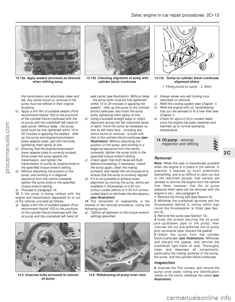
oil pump and the crankshaft left-hand oil seal carrier (see illustration). Without delay
- the sump bolts must be fully tightened
within 10 to 20 minutes of applying the
sealant - offer up the sump to the cylinder
block/crankcase, and insert the sump
bolts, tightening them lightly at first.
b) Using a suitable straight edge to check
alignment across the flat-machined faces
of each, move the sump as necessary so
that its left-hand face - including any
shims found on removal - is flush with
that of the cylinder block/crankcase (see
illustration) . Without disturbing the
position of the sump, and working in a
diagonal sequence from the centre
outwards, tighten the sump bolts to the
specified torque wrench setting.
c) Check again that both faces are flush
before proceeding; if necessary, unbolt
the sump again, clean the mating
surfaces, and repeat the full procedure to
ensure that the sump is correctly aligned.
d) If it is not possible to achieve exact
alignment by moving the sump, shims are
available in thicknesses of 0.25 mm
(colour-coded yellow) or 0.50 mm (colour-
coded black) to eliminate the discrepancy
(see illustration) .
14 The remainder of reassembly is the
reverse of the removal procedure, noting the
following points.
a) Tighten all fasteners to the torque wrench settings specified. b)
Always renew any self-locking nuts
disturbed on removal.
c) Refill the cooling system (see Chapter 1).
d) Refill the engine with oil, remembering
that you are advised to fit a new filter (see
Chapter 1).
e) Check for signs of oil or coolant leaks once the engine has been restarted and
warmed-up to normal operating
temperature.
14 Oil pump - removal,
inspection and refitting
4
Removal
Note: While this task is theoretically possible
when the engine is in place in the vehicle, in
practice, it requires so much preliminary
dismantling, and is so difficult to carry out due
to the restricted access, that owners are
advised to remove the engine from the vehicle
first. Note, however, that the oil pump
pressure relief valve can be removed with the
engine in situ - see paragraph 8.
1 Remove the timing belt (see Section 8).
2 Withdraw the crankshaft sprocket and the
thrustwasher behind it, noting which way
round the thrustwasher is fitted (see Sec-
tion 9).
3 Remove the sump (see Section 13).
4 Undo the screws securing the oil pump
pick-up/strainer pipe to the pump, then
unscrew the nut and withdraw the oil pump
pick-up/strainer pipe. Discard the gasket.
5 Unbolt the pump from the cylinder
block/crankcase (see illustration). Withdraw
and discard the gasket, and remove the
crankshaft right-hand oil seal. Thoroughly
clean and degrease all components,
particularly the mating surfaces of the pump,
the sump, and the cylinder block/crankcase.
Inspection
6 Unscrew the Torx screws, and remove the
pump cover plate; noting any identification
marks on the rotors, withdraw the rotors (see
illustration) .
Zetec engine in-car repair procedures 2C•13
13.13c Sump-to-cylinder block/crankcase
alignment shims
1 Fitting points on sump 2 Shim13.13b Checking alignment of sump with cylinder block/crankcase13.13a Apply sealant (arrowed) as directed when refitting sump
14.6 Withdrawing oil pump inner rotor14.5 Unscrew bolts (arrowed) to remove oil pump
2C
1595Ford Fiesta Remakeprocarmanuals.com
http://vnx.su
Page 69 of 296
4Check the mountings to see if the rubber is
cracked, hardened or separated from the
metal components. Sometimes, the rubber
will split right down the centre.
5 Check for relative movement between each
mounting’s brackets and the engine/
transmission or body (use a large screwdriver
or lever to attempt to move the mountings). If
movement is noted, lower the engine and
check-tighten the mounting fasteners.
Renewal
6 The engine mountings can be removed if
the weight of the engine/transmission is
supported by one of the following alternative
methods.
7 Either support the weight of the assembly
from underneath using a jack and a suitable
piece of wood between the jack saddle and
the sump or transmission (to prevent
damage), or from above by attaching a hoist
to the engine. A third method is to use a
suitable support bar with end pieces which
will engage in the water channel each side of
the bonnet lid aperture. Using an adjustable
hook and chain connected to the engine, the
weight of the engine and transmission can
then be taken from the mountings.
Engine front right-hand mounting
8 This mounting consists of a two-piece
bracket bolted to the inner wing panel,
connected by the bonded-rubber mounting
itself to a (Y-shaped) bracket, bolted (via the
alternator mounting bracket) to the cylinder
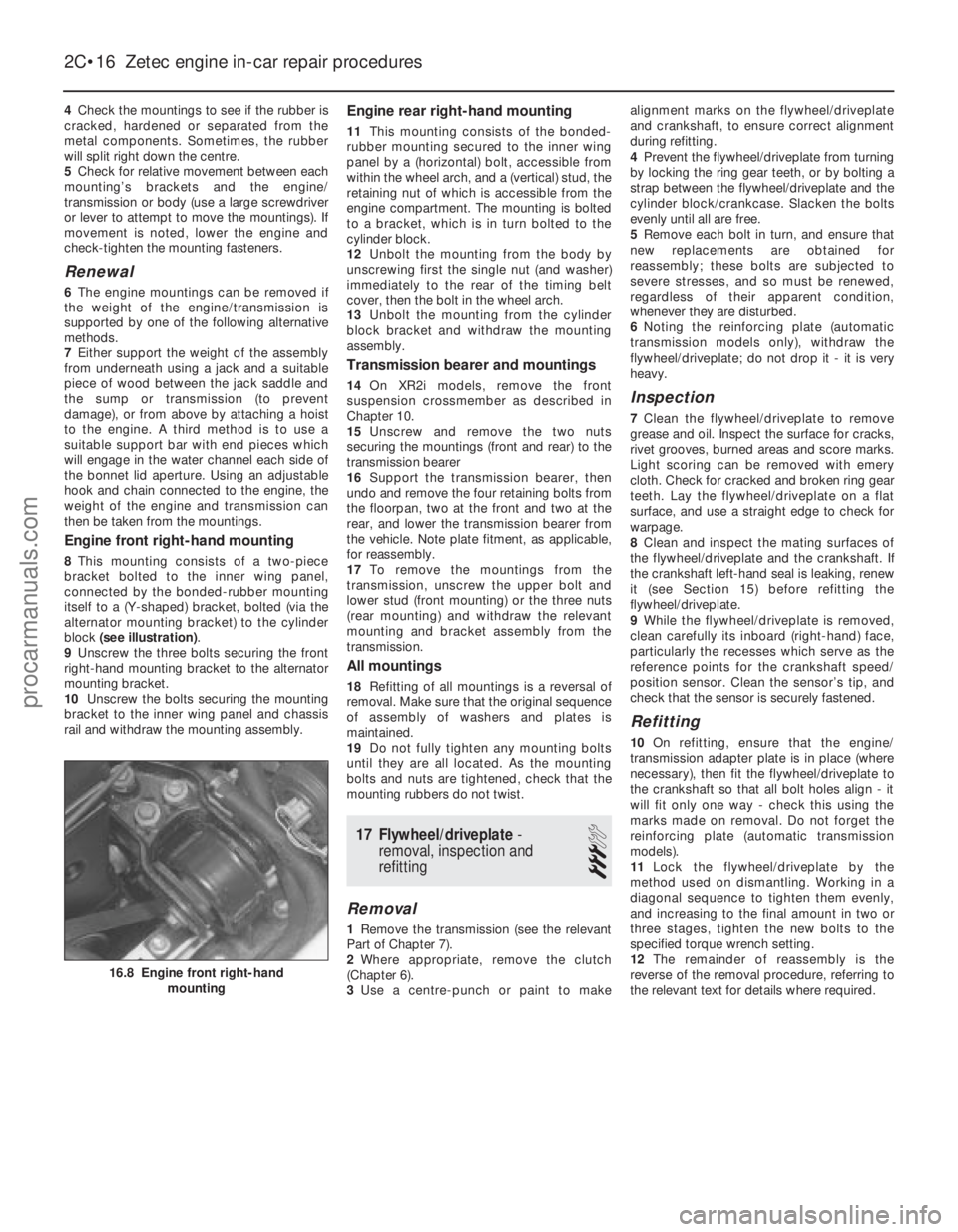
block (see illustration) .
9 Unscrew the three bolts securing the front
right-hand mounting bracket to the alternator
mounting bracket.
10 Unscrew the bolts securing the mounting
bracket to the inner wing panel and chassis
rail and withdraw the mounting assembly.
Engine rear right-hand mounting
11 This mounting consists of the bonded-
rubber mounting secured to the inner wing
panel by a (horizontal) bolt, accessible from
within the wheel arch, and a (vertical) stud, the
retaining nut of which is accessible from the
engine compartment. The mounting is bolted
to a bracket, which is in turn bolted to the
cylinder block.
12 Unbolt the mounting from the body by
unscrewing first the single nut (and washer)
immediately to the rear of the timing belt
cover, then the bolt in the wheel arch.
13 Unbolt the mounting from the cylinder
block bracket and withdraw the mounting
assembly.
Transmission bearer and mountings
14 On XR2i models, remove the front
suspension crossmember as described in
Chapter 10.
15 Unscrew and remove the two nuts
securing the mountings (front and rear) to the
transmission bearer
16 Support the transmission bearer, then
undo and remove the four retaining bolts from
the floorpan, two at the front and two at the
rear, and lower the transmission bearer from
the vehicle. Note plate fitment, as applicable,
for reassembly.
17 To remove the mountings from the
transmission, unscrew the upper bolt and
lower stud (front mounting) or the three nuts
(rear mounting) and withdraw the relevant
mounting and bracket assembly from the
transmission.
All mountings
18 Refitting of all mountings is a reversal of
removal. Make sure that the original sequence
of assembly of washers and plates is
maintained.
19 Do not fully tighten any mounting bolts
until they are all located. As the mounting
bolts and nuts are tightened, check that the
mounting rubbers do not twist.
17 Flywheel/driveplate -
removal, inspection and
refitting
3
Removal
1 Remove the transmission (see the relevant
Part of Chapter 7).
2 Where appropriate, remove the clutch
(Chapter 6).
3 Use a centre-punch or paint to make alignment marks on the flywheel/driveplate
and crankshaft, to ensure correct alignment
during refitting.
4
Prevent the flywheel/driveplate from turning
by locking the ring gear teeth, or by bolting a
strap between the flywheel/driveplate and the
cylinder block/crankcase. Slacken the bolts
evenly until all are free.
5 Remove each bolt in turn, and ensure that
new replacements are obtained for
reassembly; these bolts are subjected to
severe stresses, and so must be renewed,
regardless of their apparent condition,
whenever they are disturbed.
6 Noting the reinforcing plate (automatic
transmission models only), withdraw the
flywheel/driveplate; do not drop it - it is very
heavy.
Inspection
7 Clean the flywheel/driveplate to remove
grease and oil. Inspect the surface for cracks,
rivet grooves, burned areas and score marks.
Light scoring can be removed with emery
cloth. Check for cracked and broken ring gear
teeth. Lay the flywheel/driveplate on a flat
surface, and use a straight edge to check for
warpage.
8 Clean and inspect the mating surfaces of
the flywheel/driveplate and the crankshaft. If
the crankshaft left-hand seal is leaking, renew
it (see Section 15) before refitting the
flywheel/driveplate.
9 While the flywheel/driveplate is removed,
clean carefully its inboard (right-hand) face,
particularly the recesses which serve as the
reference points for the crankshaft speed/
position sensor. Clean the sensor’s tip, and
check that the sensor is securely fastened.
Refitting
10 On refitting, ensure that the engine/
transmission adapter plate is in place (where
necessary), then fit the flywheel/driveplate to
the crankshaft so that all bolt holes align - it
will fit only one way - check this using the
marks made on removal. Do not forget the
reinforcing plate (automatic transmission
models).
11 Lock the flywheel/driveplate by the
method used on dismantling. Working in a
diagonal sequence to tighten them evenly,
and increasing to the final amount in two or
three stages, tighten the new bolts to the
specified torque wrench setting.
12 The remainder of reassembly is the
reverse of the removal procedure, referring to
the relevant text for details where required.
2C•16 Zetec engine in-car repair procedures
16.8 Engine front right-hand mounting
1595Ford Fiesta Remakeprocarmanuals.com
http://vnx.su
Page 77 of 296
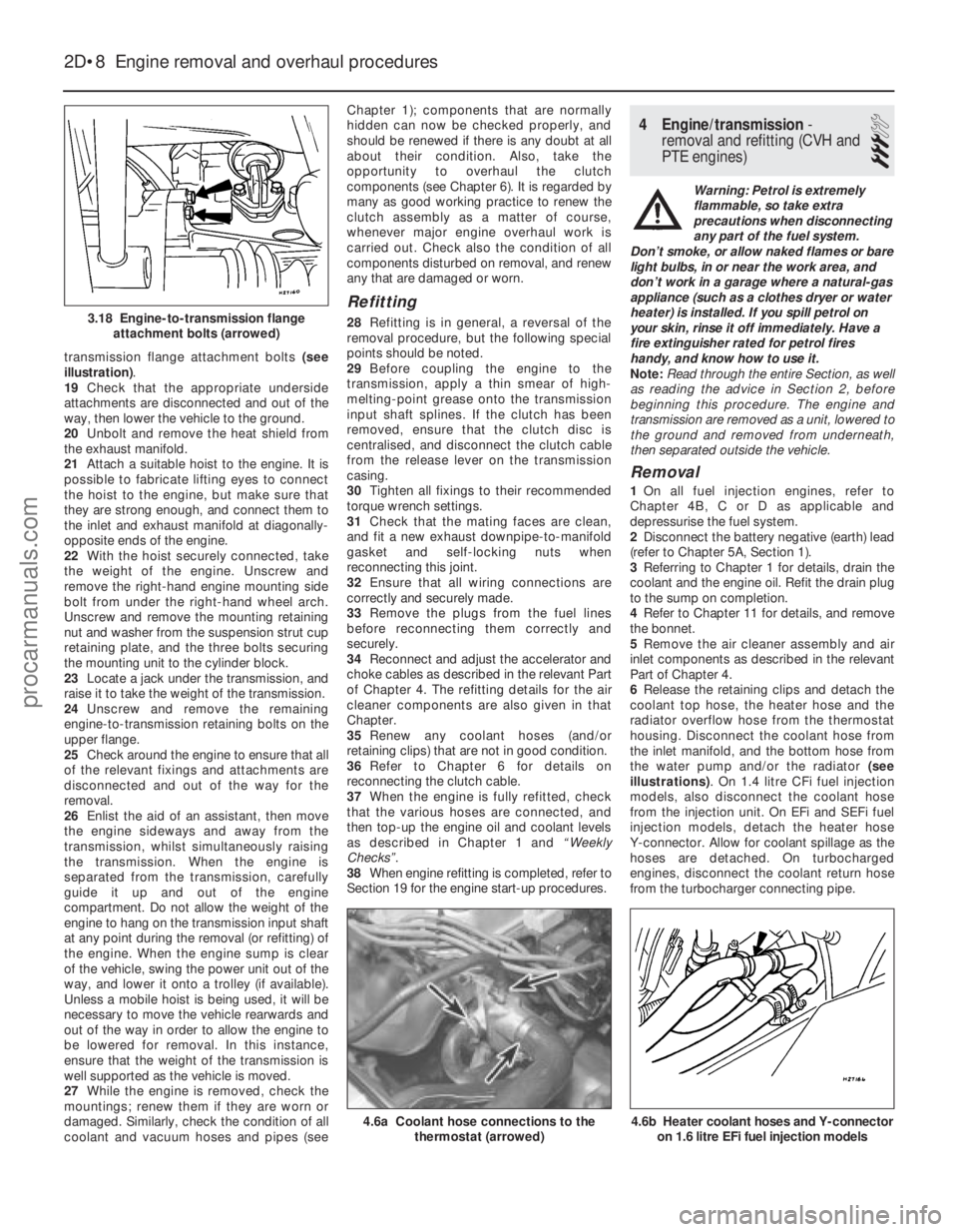
transmission flange attachment bolts (see
illustration) .
19 Check that the appropriate underside
attachments are disconnected and out of the
way, then lower the vehicle to the ground.
20 Unbolt and remove the heat shield from
the exhaust manifold.
21 Attach a suitable hoist to the engine. It is
possible to fabricate lifting eyes to connect
the hoist to the engine, but make sure that
they are strong enough, and connect them to
the inlet and exhaust manifold at diagonally-
opposite ends of the engine.
22 With the hoist securely connected, take
the weight of the engine. Unscrew and
remove the right-hand engine mounting side
bolt from under the right-hand wheel arch.
Unscrew and remove the mounting retaining
nut and washer from the suspension strut cup
retaining plate, and the three bolts securing
the mounting unit to the cylinder block.
23 Locate a jack under the transmission, and
raise it to take the weight of the transmission.
24 Unscrew and remove the remaining
engine-to-transmission retaining bolts on the
upper flange.
25 Check around the engine to ensure that all
of the relevant fixings and attachments are
disconnected and out of the way for the
removal.
26 Enlist the aid of an assistant, then move
the engine sideways and away from the
transmission, whilst simultaneously raising
the transmission. When the engine is
separated from the transmission, carefully
guide it up and out of the engine
compartment. Do not allow the weight of the
engine to hang on the transmission input shaft
at any point during the removal (or refitting) of
the engine. When the engine sump is clear
of the vehicle, swing the power unit out of the
way, and lower it onto a trolley (if available).
Unless a mobile hoist is being used, it will be
necessary to move the vehicle rearwards and
out of the way in order to allow the engine to
be lowered for removal. In this instance,
ensure that the weight of the transmission is
well supported as the vehicle is moved.
27 While the engine is removed, check the
mountings; renew them if they are worn or
damaged. Similarly, check the condition of all
coolant and vacuum hoses and pipes (see Chapter 1); components that are normally
hidden can now be checked properly, and
should be renewed if there is any doubt at all
about their condition. Also, take the
opportunity to overhaul the clutch
components (see Chapter 6). It is regarded by
many as good working practice to renew the
clutch assembly as a matter of course,
whenever major engine overhaul work is
carried out. Check also the condition of all
components disturbed on removal, and renew
any that are damaged or worn.
Refitting
28
Refitting is in general, a reversal of the
removal procedure, but the following special
points should be noted.
29 Before coupling the engine to the
transmission, apply a thin smear of high-
melting-point grease onto the transmission
input shaft splines. If the clutch has been
removed, ensure that the clutch disc is
centralised, and disconnect the clutch cable
from the release lever on the transmission
casing.
30 Tighten all fixings to their recommended
torque wrench settings.
31 Check that the mating faces are clean,
and fit a new exhaust downpipe-to-manifold
gasket and self-locking nuts when
reconnecting this joint.
32 Ensure that all wiring connections are
correctly and securely made.
33 Remove the plugs from the fuel lines
before reconnecting them correctly and
securely.
34 Reconnect and adjust the accelerator and
choke cables as described in the relevant Part
of Chapter 4. The refitting details for the air
cleaner components are also given in that
Chapter.
35 Renew any coolant hoses (and/or
retaining clips) that are not in good condition.
36 Refer to Chapter 6 for details on
reconnecting the clutch cable.
37 When the engine is fully refitted, check
that the various hoses are connected, and
then top-up the engine oil and coolant levels
as described in Chapter 1 and “Weekly
Checks”.
38 When engine refitting is completed, refer to
Section 19 for the engine start-up procedures.
4 Engine/transmission -
removal and refitting (CVH and
PTE engines)
3
Warning: Petrol is extremely
flammable, so take extra
precautions when disconnecting
any part of the fuel system.
Don’t smoke, or allow naked flames or bare
light bulbs, in or near the work area, and
don’t work in a garage where a natural-gas
appliance (such as a clothes dryer or water
heater) is installed. If you spill petrol on
your skin, rinse it off immediately. Have a
fire extinguisher rated for petrol fires
handy, and know how to use it.
Note: Read through the entire Section, as well
as reading the advice in Section 2, before
beginning this procedure. The engine and
transmission are removed as a unit, lowered to
the ground and removed from underneath,
then separated outside the vehicle.
Removal
1 On all fuel injection engines, refer to
Chapter 4B, C or D as applicable and
depressurise the fuel system.
2 Disconnect the battery negative (earth) lead
(refer to Chapter 5A, Section 1).
3 Referring to Chapter 1 for details, drain the
coolant and the engine oil. Refit the drain plug
to the sump on completion.
4 Refer to Chapter 11 for details, and remove
the bonnet.
5 Remove the air cleaner assembly and air
inlet components as described in the relevant
Part of Chapter 4.
6 Release the retaining clips and detach the
coolant top hose, the heater hose and the
radiator overflow hose from the thermostat
housing. Disconnect the coolant hose from
the inlet manifold, and the bottom hose from
the water pump and/or the radiator (see
illustrations) . On 1.4 litre CFi fuel injection
models, also disconnect the coolant hose
from the injection unit. On EFi and SEFi fuel
injection models, detach the heater hose
Y-connector. Allow for coolant spillage as the
hoses are detached. On turbocharged
engines, disconnect the coolant return hose
from the turbocharger connecting pipe.
2D•8 Engine removal and overhaul procedures
4.6b Heater coolant hoses and Y-connector on 1.6 litre EFi fuel injection models4.6a Coolant hose connections to the thermostat (arrowed)
3.18 Engine-to-transmission flangeattachment bolts (arrowed)
1595Ford Fiesta Remakeprocarmanuals.com
http://vnx.su
Page 79 of 296
25Unscrew the retaining bolt, and detach
the shift rod stabiliser from the transmission.
As it is detached, note the washer located
between the stabiliser and the transmission.
Tie the stabiliser and the shift rod up out of
the way.
Automatic transmission models
26 Unclip and detach the wiring connector
from the starter inhibitor switch (on the
transmission housing).
27 Referring to the relevant Part of Chapter 4
for details, unhook the accelerator (cam plate)
cable from the carburettor or fuel injection unit
(as applicable) at the transmission end of
the cable. Undo the retaining bolt and
detach the cable sheath bracket from the
transmission. Detach the cam plate cable
from the link.
28 Undo the two nuts from the selector cable
bracket which connects it to the lever on the
selector shaft. Disconnect the yoke from the
lever on the selector shaft and the cable from
the lever.
29 Unscrew the union nuts, and disconnect
the oil cooler feed and return pipes from the
transmission. Allow for a certain amount of
spillage, and plug the connections to prevent
the ingress of dirt.
All models
30 Unscrew the retaining nut and withdraw
the Torx-type clamp bolt securing the lower
suspension arm to the spindle carrier on each
side.
31 Refer to Chapter 10 for details, and
detach the right-hand and left-hand track rod
end balljoints from the spindle carriers.
32 On vehicles fitted with the anti-lock
braking system, refer to Chapter 9 and release
the right-hand modulator from its mounting
bracket without disconnecting the rigid brake
pipes or return hose. Tie the modulator
securely to the bulkhead. Additionally, undo
the three bolts securing the modulator
bracket.
33 Insert a suitable lever between the right-
hand driveshaft inner joint and the
transmission housing, and prise free the
driveshaft from the transmission; be prepared
for oil spillage from the transmission case
through the vacated driveshaft aperture. As it
is being prised free, simultaneously pull the
roadwheel outwards on that side, to enable
the driveshaft inboard end to separate
from the transmission. Once it is free,
suspend and support the driveshaft from the
steering gear, to prevent unnecessary strain
being placed on the driveshaft joints.
34 Insert a suitable plastic plug (or if
available, an old driveshaft joint), into the
transmission driveshaft aperture, to
immobilise the gears of the differential unit.
35 Proceed as described above in
paragraphs 33 and 34, and disconnect the
left-hand driveshaft from the transmission.
36 Connect a suitable lift hoist and sling to
the engine, connecting to the lifting eyes. When securely connected, take the weight of
the engine/transmission unit so that the
tension is relieved from the mountings.
37
Undo the retaining bolts and nuts and
detach the right-hand engine mounting from
the vehicle body.
38 Undo the four bolts securing the
transmission bearer to the underside of the
vehicle body. The transmission bearer is
removed with the engine/transmission
assembly.
39 Unscrew the three retaining bolts, and
remove the auxiliary drivebelt cover from
under the crankshaft pulley.
40 The engine/transmission unit should now
be ready for removal from the vehicle. Check
that all of the associated connections and
fittings are disconnected from the engine and
transmission, and positioned out of the way.
41 Enlist the aid of an assistant to help
steady and guide the power unit down
through the engine compartment as it is
removed. If available, position a suitable
engine trolley or crawler board under the
engine/transmission so that when lowered,
the power unit can be withdrawn from the
front end of the vehicle, and then moved to
the area where it is to be cleaned and
dismantled. On automatic transmission
models, particular care must be taken not to
damage the transmission fluid pan (sump)
during the removal and subsequent refitting
processes.
42 Carefully lower the engine and
transmission unit, ensuring that no fittings
become snagged. Detach the hoist and
remove the power unit from under the vehicle.
43 Referring to the relevant Part of Chapter 7,
separate the transmission from the engine.
44 While the engine/transmission is removed,
check the mountings; renew them if they are
worn or damaged. Similarly, check the
condition of all coolant and vacuum hoses
and pipes (see Chapter 1). Components that
are normally hidden can now be checked
properly, and should be renewed if there is
any doubt at all about their condition. Where
the vehicle is fitted with manual transmission,
take the opportunity to inspect the clutch
components (see Chapter 6). It is regarded by
many as good working practice to renew the
clutch assembly as a matter of course,
whenever major engine overhaul work is
carried out. Check also the condition of all
components (such as the transmission oil
seals) disturbed on removal, and renew any
that are damaged or worn.
Refitting
45 Refitting is a reversal of removal, however
note the following additional points:
a) Refer to the applicable Chapters and Sections as for removal.
b) Fit new spring clips to the grooves in the
inboard end of the right- and left-hand
driveshaft joints. Lubricate the splines
with transmission oil prior to fitting. c) Renew the exhaust flange gasket when
reconnecting the exhaust. Ensure that all
wires are routed clear of the exhaust
system and, on catalytic converter
models, ensure that the heat shields are
securely and correctly fitted.
d) Ensure that all earth lead connections are
clean and securely made.
e) Tighten all nuts and bolts to the specified torque.
f) Fit a new oil filter, and refill the engine and transmission with oil, with reference to
Chapter 1.
g) Refill the cooling system with reference to Chapter 1.
h) Refit the alternator and starter motor with reference to Chapter 5A.
i) Where applicable, refit the power steering pump with reference to Chapter 10.
46 When engine and transmission refitting is
complete, refer to the procedures described
in Section 19 before restarting the engine.
5 Engine/transmission -
removal and refitting
(Zetec engines)
3
Warning: Petrol is extremely
flammable, so take extra
precautions when disconnecting
any part of the fuel system.
Don’t smoke, or allow naked flames or
bare light bulbs, in or near the work area,
and don’t work in a garage where a
natural-gas appliance (such as a clothes
dryer or water heater) is installed. If you
spill petrol on your skin, rinse it off
immediately. Have a fire extinguisher rated
for petrol fires handy, and know how to
use it.
Note: Read through the entire Section, as well
as reading the advice in Section 2, before
beginning this procedure. The engine and
transmission are removed as a unit, lowered to
the ground and removed from underneath,
then separated outside the vehicle.
Removal
1 Park the vehicle on firm, level ground, apply
the handbrake firmly, and slacken the nuts
securing both front roadwheels.
2 Depressurise the fuel system as described
in Chapter 4D.
3 Disconnect the battery negative (earth) lead
(refer to Chapter 5A, Section 1).
4 Place protective covers on the wings, then
remove the bonnet (see Chapter 11).
5 Drain the cooling system and the engine oil
(see Chapter 1).
6 Remove the air inlet components and the
complete air cleaner assembly as described in
Chapter 4D.
7 Equalise the pressure in the fuel tank by
removing the filler cap, then release the fuel
feed and return quick-release couplings, and
pull the hoses off the fuel pipes. Plug or cap
all open fittings.
2D•10 Engine removal and overhaul procedures
1595Ford Fiesta Remakeprocarmanuals.com
http://vnx.su
Page 81 of 296
25On automatic transmission models, clean
around the unions, then disconnect the fluid
pipes from the transmission. Plug the
openings in the transmission and the pipe
unions after removal.
26 Refer to Chapter 10 and remove the front
suspension crossmember.
27 Unscrew the nuts to disconnect the
exhaust system front downpipe from the
manifold. Undo the nuts securing the catalytic
converter to the rear part of the exhaust
system, and remove the converter and
downpipe assembly.
28 On vehicles fitted with the anti-lock braking
system, refer to Chapter 9 and release the
right-hand modulator from its mounting
bracket without disconnecting the rigid brake
pipes or return hose. Tie the modulator
securely to the bulkhead. Additionally, undo
the three bolts securing the modulator bracket.
29 Disconnect both anti-roll bar links from
their respective suspension struts, and both
track rod end ball joints from their spindle
carriers (see Chapter 10).
30 Unscrew the retaining nut and withdraw
the Torx-type clamp bolt securing the lower
suspension arm to the spindle carrier on each
side.
31 Insert a suitable lever between the right-
hand driveshaft inner joint and the
transmission housing, and prise free the
driveshaft from the transmission; be prepared
for oil spillage from the transmission case
through the vacated driveshaft aperture. As it
is being prised free, simultaneously pull the
roadwheel outwards on that side to enable the
driveshaft inboard end to separate from the
transmission. Once it is free, suspend and
support the driveshaft from the steering gear,
to prevent unnecessary strain being placed on
the driveshaft joints.
32 Insert a suitable plastic plug (or if
available, an old driveshaft joint), into the
transmission driveshaft aperture, to
immobilise the gears of the differential unit.
33 Proceed as described above in
paragraphs 31 and 32, and disconnect the
left-hand driveshaft from the transmission.
34 Remove the oil filter, referring to Chapter 1
if necessary.
35 Connect a suitable lift hoist and sling to
the engine, connecting to the lift eyes. When
securely connected, take the weight of the
engine/transmission unit so that the tension is
relieved from the mountings.
36 Unbolt the engine rear right-hand
mounting from the body (one bolt in the wheel
arch, one nut in the engine compartment),
then unbolt the engine front right-hand
mounting from the alternator mounting
bracket. Unbolt the transmission bearer from
the underbody.
37 The engine/transmission unit should now
be hanging on the hoist only, with all
components which connect it to the rest of
the vehicle disconnected or removed, and
secured well clear of the unit. Make a final
check that this is the case. 38
Lower the engine/transmission to the
ground, and withdraw it from under the
vehicle.
39 Referring to the relevant Part of Chapter 7,
separate the transmission from the engine.
40 While the engine/transmission is removed,
check the mountings; renew them if they are
worn or damaged. Similarly, check the
condition of all coolant and vacuum hoses
and pipes (see Chapter 1); components that
are normally hidden can now be checked
properly, and should be renewed if there is
any doubt at all about their condition. Where
the vehicle is fitted with manual transmission,
take the opportunity to overhaul the clutch
components (see Chapter 6). It is regarded by
many as good working practice to renew the
clutch assembly as a matter of course,
whenever major engine overhaul work is
carried out. Check also the condition of all
components (such as the transmission oil
seals) disturbed on removal, and renew any
that are damaged or worn.
Refitting
41 Refitting is a reversal of removal, however
note the following additional points:
a) Refer to the applicable Chapters and Sections as for removal.
b) Fit new spring clips to the grooves in the
inboard end of the right- and left-hand
driveshaft joints. Lubricate the splines
with transmission oil prior to fitting.
c) Renew the exhaust flange gaskets when reconnecting the exhaust. Ensure that all
wires are routed clear of the exhaust
system, and that the heat shields are
securely and correctly fitted.
d) Ensure that all earth lead connections are
clean and securely made.
e) Tighten all nuts and bolts to the specified
torque.
f) Fit a new oil filter, and refill the engine and transmission with oil, with reference to
Chapter 1.
g) Refill the cooling system with reference to
Chapter 1.
h) Bleed the power steering system with reference to Chapter 10.
42 When engine and transmission refitting is
complete, refer to the procedures described
in Section 19 before restarting the engine.
6 Engine overhaul - preliminary information
It is much easier to dismantle and work on
the engine if it is mounted on a portable
engine stand. These stands can often be hired
from a tool hire shop. Before the engine is
mounted on a stand, the flywheel/driveplate
should be removed so that the stand bolts
can be tightened into the end of the cylinder
block/crankcase. If a stand is not available, it is possible to
dismantle the engine with it suitably supported on a sturdy, workbench or on the
floor. Be careful not to tip or drop the engine
when working without a stand.
If you intend to obtain a reconditioned
engine, all ancillaries must be removed first, to
be transferred to the replacement engine (just
as they will if you are doing a complete engine
overhaul yourself). These components include
the following:
a) Alternator/power steering pump and
mounting brackets.
b) DIS/E-DIS ignition coil unit (and mounting
bracket), distributor, HT leads and spark
plugs.
c) The thermostat and housing cover.
d) Carburettor/fuel injection system
components.
e) Inlet and exhaust manifolds.
f) Oil filter.
g) Fuel pump.
h) Engine mountings.
i) Flywheel/driveplate.
j) Water pump.
Note: When removing the external
components from the engine, pay close
attention to details that may be helpful or
important during refitting. Note the fitted
positions of gaskets, seals, washers, bolts and
other small items. If you are obtaining a “short” engine
(cylinder block/crankcase, crankshaft, pistons
and connecting rods all assembled), then the
cylinder head, timing chain/belt (together with
tensioner, tensioner and idler pulleys and
covers) sump and oil pump will have to be
removed also. If a complete overhaul is planned, the
engine can be dismantled in the order given
below, referring to Part A, B or C of this
Chapter unless otherwise stated.
a) Inlet and exhaust manifolds.
b) Timing chain/belt, tensioner and
sprockets.
c) Cylinder head.
d) Flywheel/driveplate.
e) Sump.
f) Oil pump.
g) Pistons (with connecting rods).
h) Crankshaft.
i) Camshaft and tappets (HCS engines).
7 Cylinder head - dismantling
4
Note:New and reconditioned cylinder heads
are available from the manufacturers, and from
engine overhaul specialists. Due to the fact
that some specialist tools are required for the
dismantling and inspection procedures, and
new components may not be readily available,
it may be more practical and economical for
the home mechanic to purchase a
reconditioned head, rather than to dismantle,
inspect and recondition the original head.
1 Remove the cylinder head as described in
Part A, B or C of this Chapter (as applicable).
2D•12 Engine removal and overhaul procedures
1595Ford Fiesta Remakeprocarmanuals.com
http://vnx.su
Page 83 of 296
draw the seal off the valve guide (see
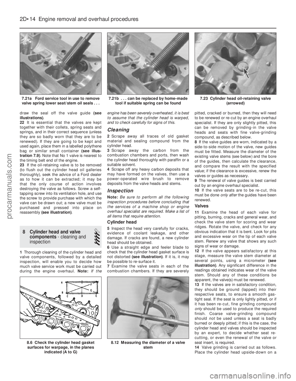
illustrations) .
22 It is essential that the valves are kept
together with their collets, spring seats and
springs, and in their correct sequence (unless
they are so badly worn that they are to be
renewed). If they are going to be kept and
used again, place them in a labelled polythene
bag or similar small container (see illus-
tration 7.9) . Note that No 1 valve is nearest to
the timing belt end of the engine.
23 If the oil-retaining valve is to be removed
(to flush out the cylinder head oil galleries
thoroughly), seek the advice of a Ford dealer
as to how it can be extracted; it may be
that the only course of action involves
destroying the valve as follows. Screw a self-
tapping screw into its ventilation hole, and use
the screw to provide purchase with which the
valve can be drawn out; a new valve must be
purchased and pressed into place on
reassembly (see illustration) .
8 Cylinder head and valve
components - cleaning and
inspection
4
1 Thorough cleaning of the cylinder head and
valve components, followed by a detailed
inspection, will enable you to decide how
much valve service work must be carried out
during the engine overhaul. Note:If the engine has been severely overheated, it is best
to assume that the cylinder head is warped,
and to check carefully for signs of this.
Cleaning
2
Scrape away all traces of old gasket
material and sealing compound from the
cylinder head.
3 Scrape away the carbon from the
combustion chambers and ports, then wash
the cylinder head thoroughly with paraffin or a
suitable solvent.
4 Scrape off any heavy carbon deposits that
may have formed on the valves, then use a
power-operated wire brush to remove
deposits from the valve heads and stems.
Inspection
Note: Be sure to perform all the following
inspection procedures before concluding that
the services of a machine shop or engine
overhaul specialist are required. Make a list of
all items that require attention.
Cylinder head
5 Inspect the head very carefully for cracks,
evidence of coolant leakage, and other
damage. If cracks are found, a new cylinder
head should be obtained.
6 Use a straight edge and feeler blade to
check that the cylinder head gasket surface is
not distorted (see illustration) . If it is, it may
be possible to re-surface it.
7 Examine the valve seats in each of the
combustion chambers. If they are severely pitted, cracked or burned, then they will need
to be renewed or re-cut by an engine overhaul
specialist. If they are only slightly pitted, this
can be removed by grinding-in the valve
heads and seats with fine valve-grinding
compound, as described below.
8
If the valve guides are worn, indicated by a
side-to-side motion of the valve, new guides
must be fitted. Measure the diameter of the
existing valve stems (see below) and the bore
of the guides, then calculate the clearance,
and compare the result with the specified
value; if the clearance is excessive, renew the
valves or guides as necessary.
9 The renewal of valve guides is best carried
out by an engine overhaul specialist.
10 If the valve seats are to be re-cut, this
must be done only afterthe guides have been
renewed.
Valves
11 Examine the head of each valve for
pitting, burning, cracks and general wear, and
check the valve stem for scoring and wear
ridges. Rotate the valve, and check for any
obvious indication that it is bent. Look for pits
and excessive wear on the tip of each valve
stem. Renew any valve that shows any such
signs of wear or damage.
12 If the valve appears satisfactory at this
stage, measure the valve stem diameter at
several points, using a micrometer (see
illustration) . Any significant difference in the
readings obtained indicates wear of the valve
stem. Should any of these conditions be
apparent, the valve(s) must be renewed.
13 If the valves are in satisfactory condition,
they should be ground (lapped) into their
respective seats, to ensure a smooth gas-
tight seal. If the seat is only lightly pitted, or if
it has been re-cut, fine grinding compound
only should be used to produce the required
finish. Coarse valve-grinding compound
should notbe used unless a seat is badly
burned or deeply pitted; if this is the case, the
cylinder head and valves should be inspected
by an expert, to decide whether seat re-
cutting, or even the renewal of the valve or
seat insert, is required.
14 Valve grinding is carried out as follows.
Place the cylinder head upside-down on a
2D•14 Engine removal and overhaul procedures
8.12 Measuring the diameter of a valve
stem8.6 Check the cylinder head gasketsurfaces for warpage, in the planes
indicated (A to G)
7.23 Cylinder head oil-retaining valve (arrowed)7.21b . . . can be replaced by home-madetool if suitable spring can be found7.21a Ford service tool in use to removevalve spring lower seat/stem oil seals . . .
1595Ford Fiesta Remakeprocarmanuals.com
http://vnx.su
Page 88 of 296
HCS engines
4Check that the main bearing caps have
marks to indicate their respective fitted
positions in the block. They also have arrow
marks pointing towards the timing chain cover
end of the engine to indicate correct
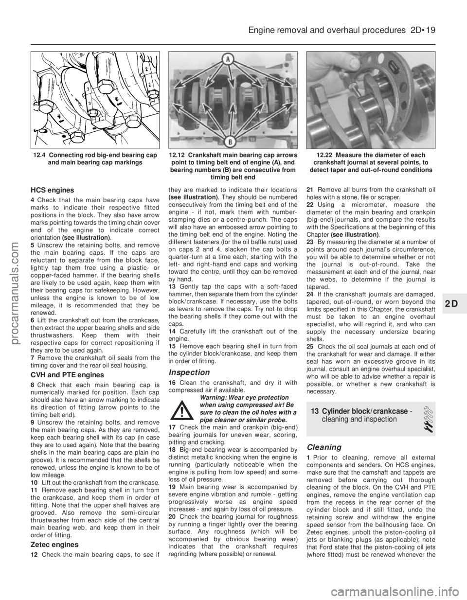
orientation (see illustration) .
5 Unscrew the retaining bolts, and remove
the main bearing caps. If the caps are
reluctant to separate from the block face,
lightly tap them free using a plastic- or
copper-faced hammer. If the bearing shells
are likely to be used again, keep them with
their bearing caps for safekeeping. However,
unless the engine is known to be of low
mileage, it is recommended that they be
renewed.
6 Lift the crankshaft out from the crankcase,
then extract the upper bearing shells and side
thrustwashers. Keep them with their
respective caps for correct repositioning if
they are to be used again.
7 Remove the crankshaft oil seals from the
timing cover and the rear oil seal housing.
CVH and PTE engines
8 Check that each main bearing cap is
numerically marked for position. Each cap
should also have an arrow marking to indicate
its direction of fitting (arrow points to the
timing belt end).
9 Unscrew the retaining bolts, and remove
the main bearing caps. As they are removed,
keep each bearing shell with its cap (in case
they are to used again). Note that the bearing
shells in the main bearing caps are plain (no
groove). It is recommended that the shells be
renewed, unless the engine is known to be of
low mileage.
10 Lift out the crankshaft from the crankcase.
11 Remove each bearing shell in turn from
the crankcase, and keep them in order of
fitting. Note that the upper shell halves are
grooved. Also remove the semi-circular
thrustwasher from each side of the central
main bearing web, and keep them in their
order of fitting.
Zetec engines
12 Check the main bearing caps, to see if they are marked to indicate their locations
(see illustration)
. They should be numbered
consecutively from the timing belt end of the
engine - if not, mark them with number-
stamping dies or a centre-punch. The caps
will also have an embossed arrow pointing to
the timing belt end of the engine. Noting the
different fasteners (for the oil baffle nuts) used
on caps 2 and 4, slacken the cap bolts a
quarter-turn at a time each, starting with the
left- and right-hand end caps and working
toward the centre, until they can be removed
by hand.
13 Gently tap the caps with a soft-faced
hammer, then separate them from the cylinder
block/crankcase. If necessary, use the bolts
as levers to remove the caps. Try not to drop
the bearing shells if they come out with the
caps.
14 Carefully lift the crankshaft out of the
engine.
15 Remove each bearing shell in turn from
the cylinder block/crankcase, and keep them
in order of fitting.
Inspection
16 Clean the crankshaft, and dry it with
compressed air if available.
Warning: Wear eye protection
when using compressed air! Be
sure to clean the oil holes with a
pipe cleaner or similar probe.
17 Check the main and crankpin (big-end)
bearing journals for uneven wear, scoring,
pitting and cracking.
18 Big-end bearing wear is accompanied by
distinct metallic knocking when the engine is
running (particularly noticeable when the
engine is pulling from low speed) and some
loss of oil pressure.
19 Main bearing wear is accompanied by
severe engine vibration and rumble - getting
progressively worse as engine speed
increases - and again by loss of oil pressure.
20 Check the bearing journal for roughness
by running a finger lightly over the bearing
surface. Any roughness (which will be
accompanied by obvious bearing wear)
indicates that the crankshaft requires
regrinding (where possible) or renewal. 21
Remove all burrs from the crankshaft oil
holes with a stone, file or scraper.
22 Using a micrometer, measure the
diameter of the main bearing and crankpin
(big-end) journals, and compare the results
with the Specifications at the beginning of this
Chapter (see illustration) .
23 By measuring the diameter at a number of
points around each journal’s circumference,
you will be able to determine whether or not
the journal is out-of-round. Take the
measurement at each end of the journal, near
the webs, to determine if the journal is
tapered.
24 If the crankshaft journals are damaged,
tapered, out-of-round, or worn beyond the
limits specified in this Chapter, the crankshaft
must be taken to an engine overhaul
specialist, who will regrind it, and who can
supply the necessary undersize bearing
shells.
25 Check the oil seal journals at each end of
the crankshaft for wear and damage. If either
seal has worn an excessive groove in its
journal, consult an engine overhaul specialist,
who will be able to advise whether a repair is
possible, or whether a new crankshaft is
necessary.
13 Cylinder block/crankcase -
cleaning and inspection
2
Cleaning
1 Prior to cleaning, remove all external
components and senders. On HCS engines,
make sure that the camshaft and tappets are
removed before carrying out thorough
cleaning of the block. On the CVH and PTE
engines, remove the engine ventilation cap
from the recess in the rear corner of the
cylinder block and if still fitted, undo the
retaining screw and withdraw the engine
speed sensor from the bellhousing face. On
Zetec engines, unbolt the piston-cooling oil
jets or blanking plugs (as applicable); note
that Ford state that the piston-cooling oil jets
(where fitted) must be renewed whenever the
Engine removal and overhaul procedures 2D•19
12.22 Measure the diameter of each
crankshaft journal at several points, to
detect taper and out-of-round conditions12.12 Crankshaft main bearing cap arrows point to timing belt end of engine (A), and
bearing numbers (B) are consecutive from timing belt end12.4 Connecting rod big-end bearing capand main bearing cap markings
2D
1595Ford Fiesta Remakeprocarmanuals.com
http://vnx.su
Page 93 of 296
careful not to scratch the bearing - use your
fingernail or the edge of a credit card.
Final crankshaft refitting
18Carefully lift the crankshaft out of the
engine. Clean the bearing surfaces of the
shells in the block, then apply a thin, uniform
layer of clean molybdenum disulphide- based
grease, engine assembly lubricant, or clean
engine oil to each surface. Coat the
thrustwasher surfaces as well.
19 Lubricate the crankshaft oil seal journals
with molybdenum disulphide-based grease,
engine assembly lubricant, or clean engine oil.
20 Make sure the crankshaft journals are
clean, then lay the crankshaft back in place in
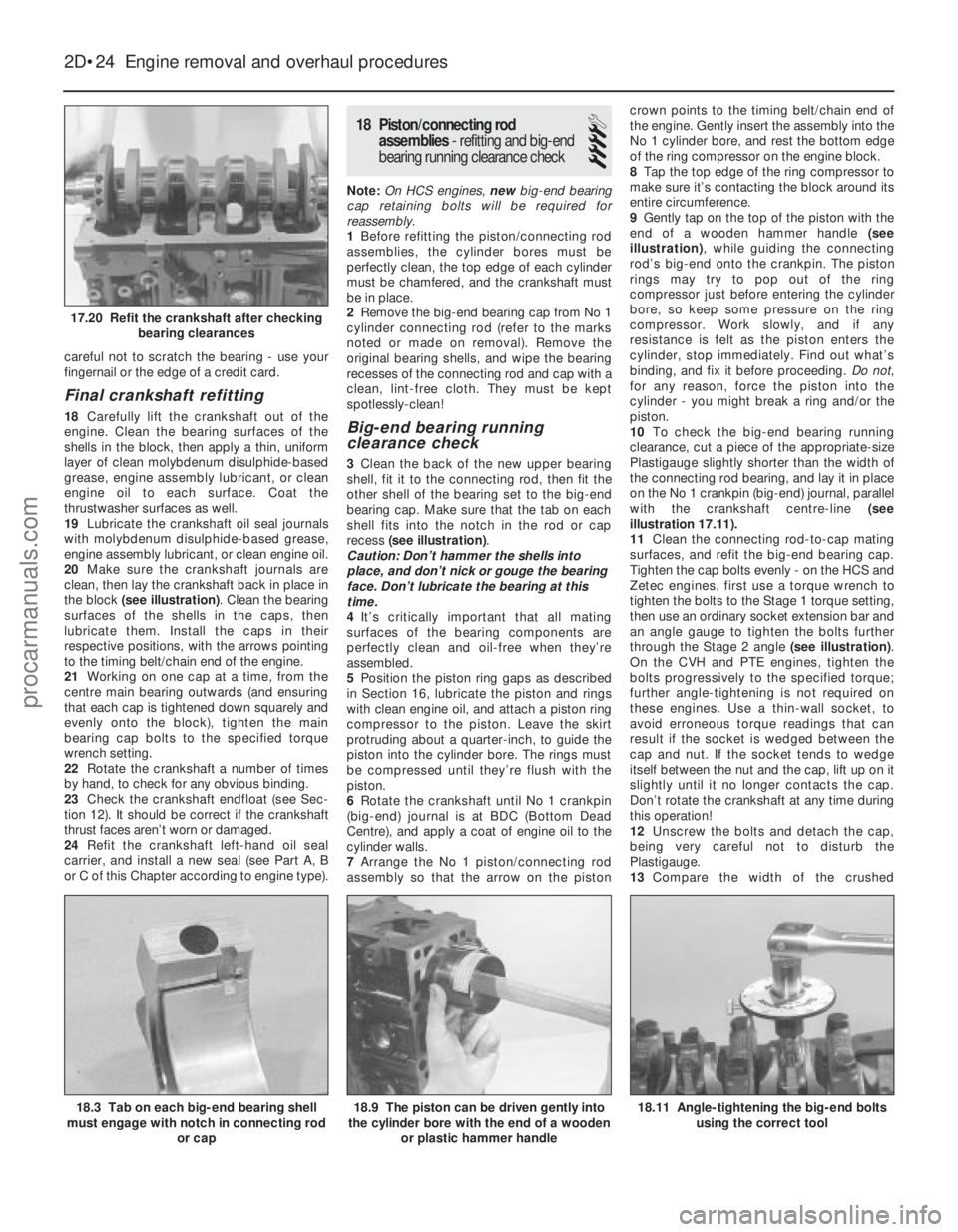
the block (see illustration) . Clean the bearing
surfaces of the shells in the caps, then
lubricate them. Install the caps in their
respective positions, with the arrows pointing
to the timing belt/chain end of the engine.
21 Working on one cap at a time, from the
centre main bearing outwards (and ensuring
that each cap is tightened down squarely and
evenly onto the block), tighten the main
bearing cap bolts to the specified torque
wrench setting.
22 Rotate the crankshaft a number of times
by hand, to check for any obvious binding.
23 Check the crankshaft endfloat (see Sec-
tion 12). It should be correct if the crankshaft
thrust faces aren’t worn or damaged.
24 Refit the crankshaft left-hand oil seal
carrier, and install a new seal (see Part A, B
or C of this Chapter according to engine type).
18 Piston/connecting rod
assemblies - refitting and big-end
bearing running clearance check
4
Note: On HCS engines, new big-end bearing
cap retaining bolts will be required for
reassembly.
1 Before refitting the piston/connecting rod
assemblies, the cylinder bores must be
perfectly clean, the top edge of each cylinder
must be chamfered, and the crankshaft must
be in place.
2 Remove the big-end bearing cap from No 1
cylinder connecting rod (refer to the marks
noted or made on removal). Remove the
original bearing shells, and wipe the bearing
recesses of the connecting rod and cap with a
clean, lint-free cloth. They must be kept
spotlessly-clean!
Big-end bearing running
clearance check
3 Clean the back of the new upper bearing
shell, fit it to the connecting rod, then fit the
other shell of the bearing set to the big-end
bearing cap. Make sure that the tab on each
shell fits into the notch in the rod or cap
recess (see illustration) .
Caution: Don’t hammer the shells into
place, and don’t nick or gouge the bearing
face. Don’t lubricate the bearing at this
time.
4 It’s critically important that all mating
surfaces of the bearing components are
perfectly clean and oil-free when they’re
assembled.
5 Position the piston ring gaps as described
in Section 16, lubricate the piston and rings
with clean engine oil, and attach a piston ring
compressor to the piston. Leave the skirt
protruding about a quarter-inch, to guide the
piston into the cylinder bore. The rings must
be compressed until they’re flush with the
piston.
6 Rotate the crankshaft until No 1 crankpin
(big-end) journal is at BDC (Bottom Dead
Centre), and apply a coat of engine oil to the
cylinder walls.
7 Arrange the No 1 piston/connecting rod
assembly so that the arrow on the piston crown points to the timing belt/chain end of
the engine. Gently insert the assembly into the
No 1 cylinder bore, and rest the bottom edge
of the ring compressor on the engine block.
8
Tap the top edge of the ring compressor to
make sure it’s contacting the block around its
entire circumference.
9 Gently tap on the top of the piston with the
end of a wooden hammer handle (see
illustration) , while guiding the connecting
rod’s big-end onto the crankpin. The piston
rings may try to pop out of the ring
compressor just before entering the cylinder
bore, so keep some pressure on the ring
compressor. Work slowly, and if any
resistance is felt as the piston enters the
cylinder, stop immediately. Find out what’s
binding, and fix it before proceeding. Do not,
for any reason, force the piston into the
cylinder - you might break a ring and/or the
piston.
10 To check the big-end bearing running
clearance, cut a piece of the appropriate-size
Plastigauge slightly shorter than the width of
the connecting rod bearing, and lay it in place
on the No 1 crankpin (big-end) journal, parallel
with the crankshaft centre-line (see
illustration 17.11).
11 Clean the connecting rod-to-cap mating
surfaces, and refit the big-end bearing cap.
Tighten the cap bolts evenly - on the HCS and
Zetec engines, first use a torque wrench to
tighten the bolts to the Stage 1 torque setting,
then use an ordinary socket extension bar and
an angle gauge to tighten the bolts further
through the Stage 2 angle (see illustration).
On the CVH and PTE engines, tighten the
bolts progressively to the specified torque;
further angle-tightening is not required on
these engines. Use a thin-wall socket, to
avoid erroneous torque readings that can
result if the socket is wedged between the
cap and nut. If the socket tends to wedge
itself between the nut and the cap, lift up on it
slightly until it no longer contacts the cap.
Don’t rotate the crankshaft at any time during
this operation!
12 Unscrew the bolts and detach the cap,
being very careful not to disturb the
Plastigauge.
13 Compare the width of the crushed
2D•24 Engine removal and overhaul procedures
18.11 Angle-tightening the big-end bolts
using the correct tool18.9 The piston can be driven gently into
the cylinder bore with the end of a wooden
or plastic hammer handle18.3 Tab on each big-end bearing shell
must engage with notch in connecting rod
or cap
17.20 Refit the crankshaft after checkingbearing clearances
1595Ford Fiesta Remakeprocarmanuals.com
http://vnx.su