1989 FORD FIESTA oil change
[x] Cancel search: oil changePage 50 of 296
bolt(s) securing the gearchange mechanism
stabiliser bar/exhaust forward mounting
bracket (where fitted) and ease it out of the
way.
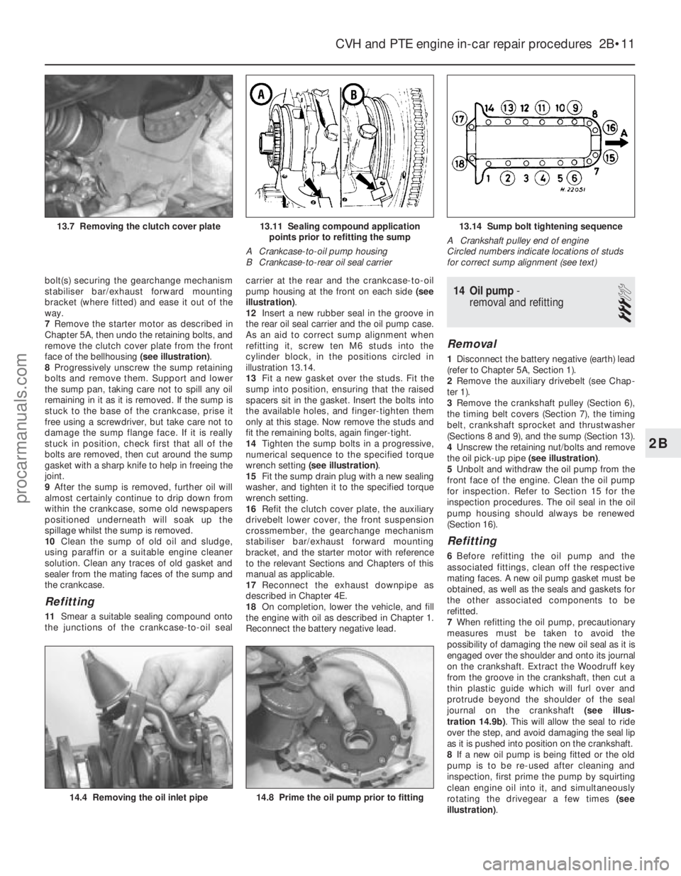
7Remove the starter motor as described in
Chapter 5A, then undo the retaining bolts, and
remove the clutch cover plate from the front
face of the bellhousing (see illustration).
8 Progressively unscrew the sump retaining
bolts and remove them. Support and lower
the sump pan, taking care not to spill any oil
remaining in it as it is removed. If the sump is
stuck to the base of the crankcase, prise it
free using a screwdriver, but take care not to
damage the sump flange face. If it is really
stuck in position, check first that all of the
bolts are removed, then cut around the sump
gasket with a sharp knife to help in freeing the
joint.
9 After the sump is removed, further oil will
almost certainly continue to drip down from
within the crankcase, some old newspapers
positioned underneath will soak up the
spillage whilst the sump is removed.
10 Clean the sump of old oil and sludge,
using paraffin or a suitable engine cleaner
solution. Clean any traces of old gasket and
sealer from the mating faces of the sump and
the crankcase.
Refitting
11 Smear a suitable sealing compound onto
the junctions of the crankcase-to-oil seal carrier at the rear and the crankcase-to-oil
pump housing at the front on each side
(see
illustration) .
12 Insert a new rubber seal in the groove in
the rear oil seal carrier and the oil pump case.
As an aid to correct sump alignment when
refitting it, screw ten M6 studs into the
cylinder block, in the positions circled in
illustration 13.14.
13 Fit a new gasket over the studs. Fit the
sump into position, ensuring that the raised
spacers sit in the gasket. Insert the bolts into
the available holes, and finger-tighten them
only at this stage. Now remove the studs and
fit the remaining bolts, again finger-tight.
14 Tighten the sump bolts in a progressive,
numerical sequence to the specified torque
wrench setting (see illustration) .
15 Fit the sump drain plug with a new sealing
washer, and tighten it to the specified torque
wrench setting.
16 Refit the clutch cover plate, the auxiliary
drivebelt lower cover, the front suspension
crossmember, the gearchange mechanism
stabiliser bar/exhaust forward mounting
bracket, and the starter motor with reference
to the relevant Sections and Chapters of this
manual as applicable.
17 Reconnect the exhaust downpipe as
described in Chapter 4E.
18 On completion, lower the vehicle, and fill
the engine with oil as described in Chapter 1.
Reconnect the battery negative lead.
14 Oil pump -
removal and refitting
3
Removal
1 Disconnect the battery negative (earth) lead
(refer to Chapter 5A, Section 1).
2 Remove the auxiliary drivebelt (see Chap-
ter 1).
3 Remove the crankshaft pulley (Section 6),
the timing belt covers (Section 7), the timing
belt, crankshaft sprocket and thrustwasher
(Sections 8 and 9), and the sump (Section 13).
4 Unscrew the retaining nut/bolts and remove
the oil pick-up pipe (see illustration).
5 Unbolt and withdraw the oil pump from the
front face of the engine. Clean the oil pump
for inspection. Refer to Section 15 for the
inspection procedures. The oil seal in the oil
pump housing should always be renewed
(Section 16).
Refitting
6 Before refitting the oil pump and the
associated fittings, clean off the respective
mating faces. A new oil pump gasket must be
obtained, as well as the seals and gaskets for
the other associated components to be
refitted.
7 When refitting the oil pump, precautionary
measures must be taken to avoid the
possibility of damaging the new oil seal as it is
engaged over the shoulder and onto its journal
on the crankshaft. Extract the Woodruff key
from the groove in the crankshaft, then cut a
thin plastic guide which will furl over and
protrude beyond the shoulder of the seal
journal on the crankshaft (see illus-
tration 14.9b) . This will allow the seal to ride
over the step, and avoid damaging the seal lip
as it is pushed into position on the crankshaft.
8 If a new oil pump is being fitted or the old
pump is to be re-used after cleaning and
inspection, first prime the pump by squirting
clean engine oil into it, and simultaneously
rotating the drivegear a few times (see
illustration) .
CVH and PTE engine in-car repair procedures 2B•11
13.14 Sump bolt tightening sequence
A Crankshaft pulley end of engine
Circled numbers indicate locations of studs
for correct sump alignment (see text)13.11 Sealing compound application points prior to refitting the sump
A Crankcase-to-oil pump housing
B Crankcase-to-rear oil seal carrier13.7 Removing the clutch cover plate
14.8 Prime the oil pump prior to fitting14.4 Removing the oil inlet pipe
2B
1595Ford Fiesta Remakeprocarmanuals.com
http://vnx.su
Page 56 of 296
fitted with three piston rings: two
compression rings and an oil control ring.
After manufacture, the cylinder bores and
piston skirts are measured and classified into
three grades, which must be carefully
matched together, to ensure the correct
piston/cylinder clearance; no oversizes are
available to permit reboring.The inlet and exhaust valves are each
closed by coil springs; they operate in guides
which are shrink-fitted into the cylinder head,
as are the valve seat inserts. Both camshafts are driven by the same
toothed timing belt, each operating eight
valves via self-adjusting hydraulic tappets,
thus eliminating the need for routine checking
and adjustment of the valve clearances. Each
camshaft rotates in five bearings that are line-
bored directly in the cylinder head and the
(bolted-on) bearing caps; this means that the
bearing caps are not available separately from
the cylinder head, and must not be
interchanged with caps from another engine. The water pump is bolted to the right-hand
end of the cylinder block, inboard of the
timing belt, and is driven with the power
steering pump and alternator by a flat
“polyvee”-type auxiliary drivebelt from the
crankshaft pulley.
When working on this engine, note that
Torx-type (both male and female heads) and
hexagon socket (Allen head) fasteners are
widely used; a good selection of bits, with the
necessary adapters, will be required, so that
these can be unscrewed without damage and,
on reassembly, tightened to the torque
wrench settings specified. Lubrication is by means of an eccentric-
rotor trochoidal pump, which is mounted on
the crankshaft right-hand end, and draws oil
through a strainer located in the sump. The
pump forces oil through an externally-
mounted full-flow cartridge-type filter - on
some versions of the engine, an oil cooler is
fitted to the oil filter mounting, so that clean oil
entering the engine’s galleries is cooled by the
main engine cooling system.
Repair operations possible with
the engine in the car
The following work can be carried out with
the engine in the car:
a) Compression pressure - testing.
b) Cylinder head cover - removal and
refitting.
c) Timing belt covers - removal and refitting.
d) Timing belt - renewal.
e) Timing belt tensioner and sprockets - removal and refitting.
f) Camshaft oil seals - renewal.
g) Camshafts and hydraulic tappets - removal and refitting.
h) Cylinder head - removal and refitting.
i) Cylinder head and pistons - decarbonising.
j) Sump - removal and refitting.
k) Crankshaft oil seals - renewal.
l) Oil pump - removal and refitting. m)
Flywheel/driveplate - removal and
refitting.
n) Engine/transmission mountings - removal and refitting.
Note: It is possible to remove the pistons and
connecting rods (after removing the cylinder
head and sump) without removing the engine.
However, this is not recommended. Work of
this nature is more easily and thoroughly
completed with the engine on the bench, as
described in Chapter 2D.
2 Compression test -
description and interpretation
2
Refer to Section 2 in Part A of this Chapter.
3 Top Dead Centre (TDC) for No 1 piston - locating
2
1Top dead centre (TDC) is the highest point
of the cylinder that each piston reaches as the
crankshaft turns. Each piston reaches its TDC
position at the end of its compression stroke,
and then again at the end of its exhaust
stroke. For the purpose of engine timing, TDC
on the compression stroke for No 1 piston is
used. No 1 cylinder is at the timing belt end of
the engine. Proceed as follows.
2 Disconnect the battery negative (earth) lead
(refer to Chapter 5A, Section 1).
3 Chock the rear wheels then jack up the
front of the car and support it on axle stands
(see “Jacking and Vehicle Support” ). Remove
the right-hand roadwheel.
4 Remove the auxiliary drivebelt cover (see
Chapter 1) to expose the crankshaft pulley
and timing marks.
5 Fit a spanner onto the crankshaft pulley
bolt, and turn the crankshaft in its normal
direction of rotation (clockwise, viewed from
the pulley end). 6
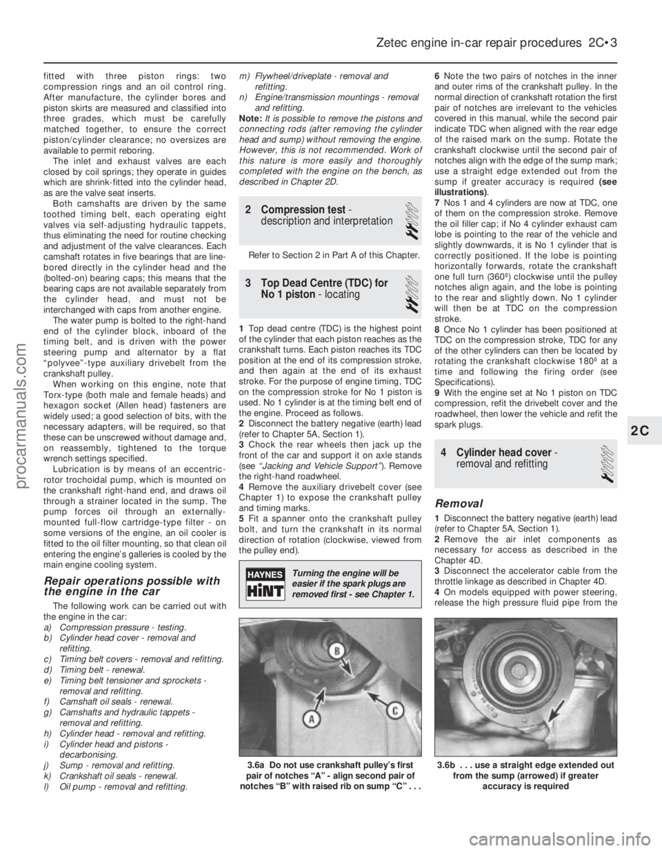
Note the two pairs of notches in the inner
and outer rims of the crankshaft pulley. In the
normal direction of crankshaft rotation the first
pair of notches are irrelevant to the vehicles
covered in this manual, while the second pair
indicate TDC when aligned with the rear edge
of the raised mark on the sump. Rotate the
crankshaft clockwise until the second pair of
notches align with the edge of the sump mark;
use a straight edge extended out from the
sump if greater accuracy is required (see
illustrations) .
7 Nos 1 and 4 cylinders are now at TDC, one
of them on the compression stroke. Remove
the oil filler cap; if No 4 cylinder exhaust cam
lobe is pointing to the rear of the vehicle and
slightly downwards, it is No 1 cylinder that is
correctly positioned. If the lobe is pointing
horizontally forwards, rotate the crankshaft
one full turn (360º) clockwise until the pulley
notches align again, and the lobe is pointing
to the rear and slightly down. No 1 cylinder
will then be at TDC on the compression
stroke.
8 Once No 1 cylinder has been positioned at
TDC on the compression stroke, TDC for any
of the other cylinders can then be located by
rotating the crankshaft clockwise 180º at a
time and following the firing order (see
Specifications).
9 With the engine set at No 1 piston on TDC
compression, refit the drivebelt cover and the
roadwheel, then lower the vehicle and refit the
spark plugs.
4 Cylinder head cover -
removal and refitting
1
Removal
1 Disconnect the battery negative (earth) lead
(refer to Chapter 5A, Section 1).
2 Remove the air inlet components as
necessary for access as described in the
Chapter 4D.
3 Disconnect the accelerator cable from the
throttle linkage as described in Chapter 4D.
4 On models equipped with power steering,
release the high pressure fluid pipe from the
Zetec engine in-car repair procedures 2C•3
3.6b . . . use a straight edge extended out from the sump (arrowed) if greater
accuracy is required3.6a Do not use crankshaft pulley’s first
pair of notches “A” - align second pair of
notches “B” with raised rib on sump “C” . . .
2C
1595Ford Fiesta Remake
Turning the engine will be
easier if the spark plugs are
removed first - see Chapter 1.
procarmanuals.com
http://vnx.su
Page 61 of 296
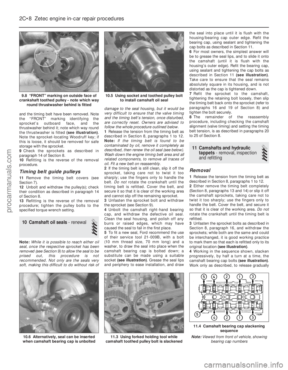
and the timing belt have been removed. Note
the “FRONT” marking identifying the
sprocket’s outboard face, and the
thrustwasher behind it; note which way round
the thrustwasher is fitted (see illustration).
Note the sprocket-locating Woodruff key; if
this is loose, it should be removed for safe
storage with the sprocket.
9 Check the sprockets as described in
paragraph 14 of Section 8.
10 Refitting is the reverse of the removal
procedure.
Timing belt guide pulleys
11 Remove the timing belt covers (see
Section 7).
12 Unbolt and withdraw the pulley(s); check
their condition as described in paragraph 14
of Section 8.
13 Refitting is the reverse of the removal
procedure; tighten the pulley bolts to the
specified torque wrench setting.
10 Camshaft oil seals - renewal
4
Note:While it is possible to reach either oil
seal, once the respective sprocket has been
removed (see Section 9) to allow the seal to be
prised out, this procedure is not
recommended. Not only are the seals very
soft, making this difficult to do without risk of damage to the seal housing, but it would be
very difficult to ensure that the valve timing
and the timing belt’s tension, once disturbed,
are correctly reset. Owners are advised to
follow the whole procedure outlined below.
1
Release the tension from the timing belt as
described in Section 8, paragraphs 1 to 12.
Note: If the timing belt is found to be
contaminated by oil, remove it completely as
described, then renew the oil seal (see below).
Wash down the engine timing belt area and all
related components, to remove all traces of
oil. Fit a new belt on reassembly.
2 If the timing belt is still clean, slip it off the
sprocket, taking care not to twist it too
sharply; use the fingers only to handle the
belt. Do not rotate the crankshaft until the
timing belt is refitted. Cover the belt, and
secure it so that it is clear of the working area
and cannot slip off the remaining sprocket.
3 Unfasten the sprocket bolt and withdraw
the sprocket (see Section 9).
4 Unbolt the camshaft right-hand bearing
cap, and withdraw the defective oil seal.
Clean the seal housing, and polish off any
burrs or raised edges, which may have
caused the seal to fail in the first place.
5 To fit a new seal, Ford recommend the use
of their service tool 21-009B, with a bolt
(10 mm thread size, 70 mm long) and a
washer, to draw the seal into place when the
camshaft bearing cap is bolted down; a
substitute can be made using a suitable
socket (see illustration) . Grease the seal lips
and periphery to ease installation, and draw the seal into place until it is flush with the
housing/bearing cap outer edge. Refit the
bearing cap, using sealant and tightening the
cap bolts as described in Section 11.
6
For most owners, the simplest answer will
be to grease the seal lips, and to slide it onto
the camshaft (until it is flush with the
housing’s outer edge). Refit the bearing cap,
using sealant and tightening the cap bolts as
described in Section 11 (see illustration).
Take care to ensure that the seal remains
absolutely square in its housing, and is not
distorted as the cap is tightened down.
7 Refit the sprocket to the camshaft,
tightening the retaining bolt loosely, then slip
the timing belt back onto the sprocket (refer to
paragraphs 16 and 19 of Section 8) and
tighten the bolt securely.
8 The remainder of the reassembly
procedure, including checking the camshaft
alignment (valve timing) and setting the timing
belt tension, is as described in paragraphs 20
to 25 of Section 8.
11 Camshafts and hydraulic tappets - removal, inspection
and refitting
4
Removal
1 Release the tension from the timing belt as
described in Section 8, paragraphs 1 to 12.
2 Either remove the timing belt completely
(Section 8, paragraphs 13 and 14) or slip it off
the camshaft sprockets, taking care not to
twist it too sharply; use the fingers only to
handle the belt. Cover the belt, and secure it
so that it is clear of the working area. Do not
rotate the crankshaft until the timing belt is
refitted.
3 Unfasten the sprocket bolts as described in
Section 8, paragraph 16, and withdraw the
sprockets; while both are the same and could
be interchanged, it is good working practice
to mark them so that each is refitted only to its
original location (see illustration) .
4 Working in the sequence shown, slacken
progressively, by half a turn at a time, the
camshaft bearing cap bolts (see illustration).
Work only as described, to release gradually
2C•8 Zetec engine in-car repair procedures
11.4 Camshaft bearing cap slackening
sequence
Note: Viewed from front of vehicle, showing
bearing cap numbers
11.3 Using forked holding tool while
camshaft toothed pulley bolt is slackened10.6 Alternatively, seal can be inserted
when camshaft bearing cap is unbolted
10.5 Using socket and toothed pulley bolt to install camshaft oil seal9.8 “FRONT” marking on outside face of
crankshaft toothed pulley - note which way round thrustwasher behind is fitted
1595Ford Fiesta Remakeprocarmanuals.com
http://vnx.su
Page 62 of 296
and evenly the pressure of the valve springs
on the caps.
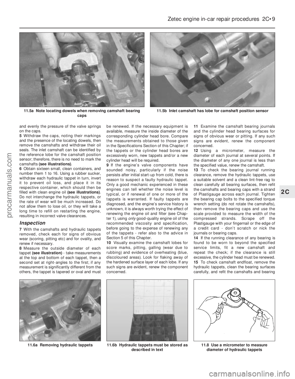
5Withdraw the caps, noting their markings
and the presence of the locating dowels, then
remove the camshafts and withdraw their oil
seals. The inlet camshaft can be identified by
the reference lobe for the camshaft position
sensor; therefore, there is no need to mark the
camshafts (see illustrations) .
6 Obtain sixteen small, clean containers, and
number them 1 to 16. Using a rubber sucker,
withdraw each hydraulic tappet in turn, invert
it to prevent oil loss, and place it in its
respective container, which should then be
filled with clean engine oil (see illustrations).
Do not interchange the hydraulic tappets, or
the rate of wear will be much increased. Do
not allow them to lose oil, or they will take a
long time to refill on restarting the engine,
resulting in incorrect valve clearances.
Inspection
7 With the camshafts and hydraulic tappets
removed, check each for signs of obvious
wear (scoring, pitting etc) and for ovality, and
renew if necessary.
8 Measure the outside diameter of each
tappet (see illustration) - take measurements
at the top and bottom of each tappet, then a
second set at right-angles to the first; if any
measurement is significantly different from the
others, the tappet is tapered or oval and must be renewed. If the necessary equipment is
available, measure the inside diameter of the
corresponding cylinder head bore. Compare
the measurements obtained to those given
in the Specifications Section of this Chapter; if
the tappets or the cylinder head bores are
excessively worn, new tappets and/or a new
cylinder head will be required.
9
If the engine’s valve components have
sounded noisy, particularly if the noise
persists after initial start-up from cold, there is
reason to suspect a faulty hydraulic tappet.
Only a good mechanic experienced in these
engines can tell whether the noise level is
typical, or if renewal of one or more of the
tappets is warranted. If faulty tappets are
diagnosed, and the engine’s service history is
unknown, it is always worth trying the effect of
renewing the engine oil and filter (see Chap-
ter 1), using onlygood-quality engine oil of the
recommended viscosity and specification,
before going to the expense of renewing any
of the tappets - refer also to the advice in
Section 5 of this Chapter.
10 Visually examine the camshaft lobes for
score marks, pitting, galling (wear due to
rubbing) and evidence of overheating (blue,
discoloured areas). Look for flaking away of
the hardened surface layer of each lobe. If any
such signs are evident, renew the component
concerned. 11
Examine the camshaft bearing journals
and the cylinder head bearing surfaces for
signs of obvious wear or pitting. If any such
signs are evident, renew the component
concerned.
12 Using a micrometer, measure the
diameter of each journal at several points. If
the diameter of any one journal is less than
the specified value, renew the camshaft.
13 To check the bearing journal running
clearance, remove the hydraulic tappets, use
a suitable solvent and a clean lint-free rag to
clean carefully all bearing surfaces, then refit
the camshafts and bearing caps with a strand
of Plastigauge across each journal. Tighten
the bearing cap bolts to the specified torque
wrench setting (do not rotate the camshafts),
then remove the bearing caps and use the
scale provided to measure the width of the
compressed strands. Scrape off the
Plastigauge with your fingernail or the edge of
a credit card - don’t scratch or nick the
journals or bearing caps.
14 If the running clearance of any bearing is
found to be worn to beyond the specified
service limits, fit a new camshaft and
repeat the check; if the clearance is still
excessive, the cylinder head must be renewed.
15 To check camshaft endfloat, remove the
hydraulic tappets, clean the bearing surfaces
carefully, and refit the camshafts and bearing
Zetec engine in-car repair procedures 2C•9
11.6a Removing hydraulic tappets
11.5b Inlet camshaft has lobe for camshaft position sensor11.5a Note locating dowels when removing camshaft bearing caps
11.8 Use a micrometer to measurediameter of hydraulic tappets11.6b Hydraulic tappets must be stored as described in text
2C
1595Ford Fiesta Remakeprocarmanuals.com
http://vnx.su
Page 78 of 296
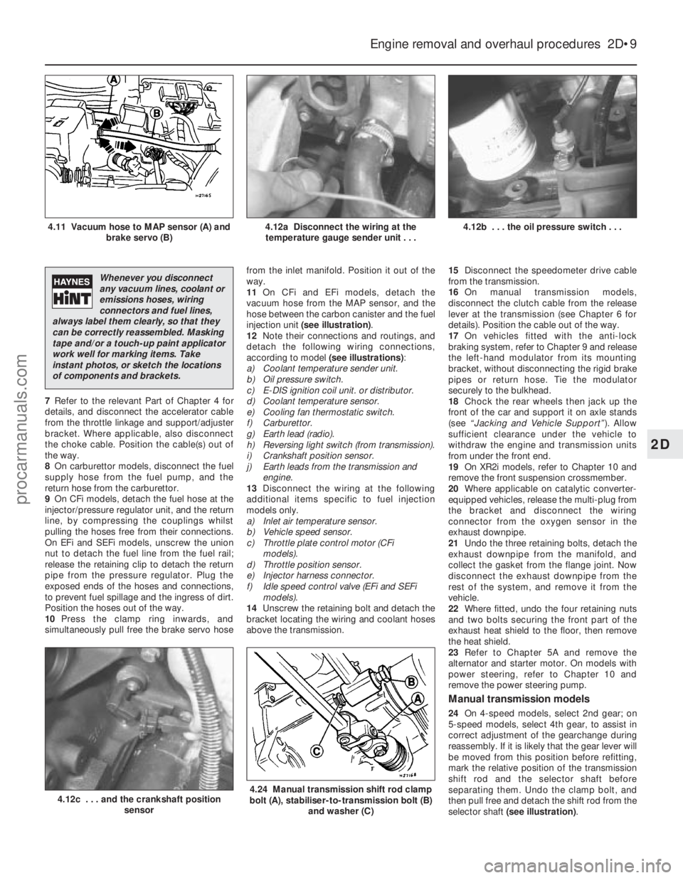
7Refer to the relevant Part of Chapter 4 for
details, and disconnect the accelerator cable
from the throttle linkage and support/adjuster
bracket. Where applicable, also disconnect
the choke cable. Position the cable(s) out of
the way.
8 On carburettor models, disconnect the fuel
supply hose from the fuel pump, and the
return hose from the carburettor.
9 On CFi models, detach the fuel hose at the
injector/pressure regulator unit, and the return
line, by compressing the couplings whilst
pulling the hoses free from their connections.
On EFi and SEFi models, unscrew the union
nut to detach the fuel line from the fuel rail;
release the retaining clip to detach the return
pipe from the pressure regulator. Plug the
exposed ends of the hoses and connections,
to prevent fuel spillage and the ingress of dirt.
Position the hoses out of the way.
10 Press the clamp ring inwards, and
simultaneously pull free the brake servo hose from the inlet manifold. Position it out of the
way.
11
On CFi and EFi models, detach the
vacuum hose from the MAP sensor, and the
hose between the carbon canister and the fuel
injection unit (see illustration) .
12 Note their connections and routings, and
detach the following wiring connections,
according to model (see illustrations):
a) Coolant temperature sender unit.
b) Oil pressure switch.
c) E-DIS ignition coil unit. or distributor.
d) Coolant temperature sensor.
e) Cooling fan thermostatic switch.
f) Carburettor.
g) Earth lead (radio).
h) Reversing light switch (from transmission).
i) Crankshaft position sensor.
j) Earth leads from the transmission and engine.
13 Disconnect the wiring at the following
additional items specific to fuel injection
models only.
a) Inlet air temperature sensor.
b) Vehicle speed sensor.
c) Throttle plate control motor (CFi models).
d) Throttle position sensor.
e) Injector harness connector.
f) Idle speed control valve (EFi and SEFi models).
14 Unscrew the retaining bolt and detach the
bracket locating the wiring and coolant hoses
above the transmission. 15
Disconnect the speedometer drive cable
from the transmission.
16 On manual transmission models,
disconnect the clutch cable from the release
lever at the transmission (see Chapter 6 for
details). Position the cable out of the way.
17 On vehicles fitted with the anti-lock
braking system, refer to Chapter 9 and release
the left-hand modulator from its mounting
bracket, without disconnecting the rigid brake
pipes or return hose. Tie the modulator
securely to the bulkhead.
18 Chock the rear wheels then jack up the
front of the car and support it on axle stands
(see “Jacking and Vehicle Support” ). Allow
sufficient clearance under the vehicle to
withdraw the engine and transmission units
from under the front end.
19 On XR2i models, refer to Chapter 10 and
remove the front suspension crossmember.
20 Where applicable on catalytic converter-
equipped vehicles, release the multi-plug from
the bracket and disconnect the wiring
connector from the oxygen sensor in the
exhaust downpipe.
21 Undo the three retaining bolts, detach the
exhaust downpipe from the manifold, and
collect the gasket from the flange joint. Now
disconnect the exhaust downpipe from the
rest of the system, and remove it from the
vehicle.
22 Where fitted, undo the four retaining nuts
and two bolts securing the front part of the
exhaust heat shield to the floor, then remove
the heat shield.
23 Refer to Chapter 5A and remove the
alternator and starter motor. On models with
power steering, refer to Chapter 10 and
remove the power steering pump.
Manual transmission models
24 On 4-speed models, select 2nd gear; on
5-speed models, select 4th gear, to assist in
correct adjustment of the gearchange during
reassembly. If it is likely that the gear lever will
be moved from this position before refitting,
mark the relative position of the transmission
shift rod and the selector shaft before
separating them. Undo the clamp bolt, and
then pull free and detach the shift rod from the
selector shaft (see illustration) .
Engine removal and overhaul procedures 2D•9
4.12b . . . the oil pressure switch . . .4.12a Disconnect the wiring at the
temperature gauge sender unit . . .4.11 Vacuum hose to MAP sensor (A) and brake servo (B)
4.24 Manual transmission shift rod clamp
bolt (A), stabiliser-to-transmission bolt (B)
and washer (C)4.12c . . . and the crankshaft position sensor
2D
1595Ford Fiesta Remake
Whenever you disconnect
any vacuum lines, coolant or
emissions hoses, wiring
connectors and fuel lines,
always label them clearly, so that they
can be correctly reassembled. Masking
tape and/or a touch-up paint applicator
work well for marking items. Take
instant photos, or sketch the locations
of components and brackets.
procarmanuals.com
http://vnx.su
Page 80 of 296
8Disconnect the accelerator cable from the
throttle linkage as described in Chapter 4D.
Secure the cable clear of the
engine/transmission.
9 Releasing its wire clip, unplug the wiring
connector from the power steering pressure
switch (where fitted), then disconnect the
earth cable from the engine lifting eye. Refit
the bolt after disconnecting the cable.
10 Marking or labelling all components as
they are disconnected, disconnect the
vacuum hoses as follows:
a) From the rear of the inlet manifold.
b) The braking system vacuum servo unit
hose - from the inlet manifold (see
Chapter 9 for details).
c) While you are there, trace the vacuum line
from the pulse-air filter housing, and
disconnect it from the pulse-air solenoid
valve.
d) Secure all these hoses so that they won’t
get damaged as the engine/transmission
is removed.
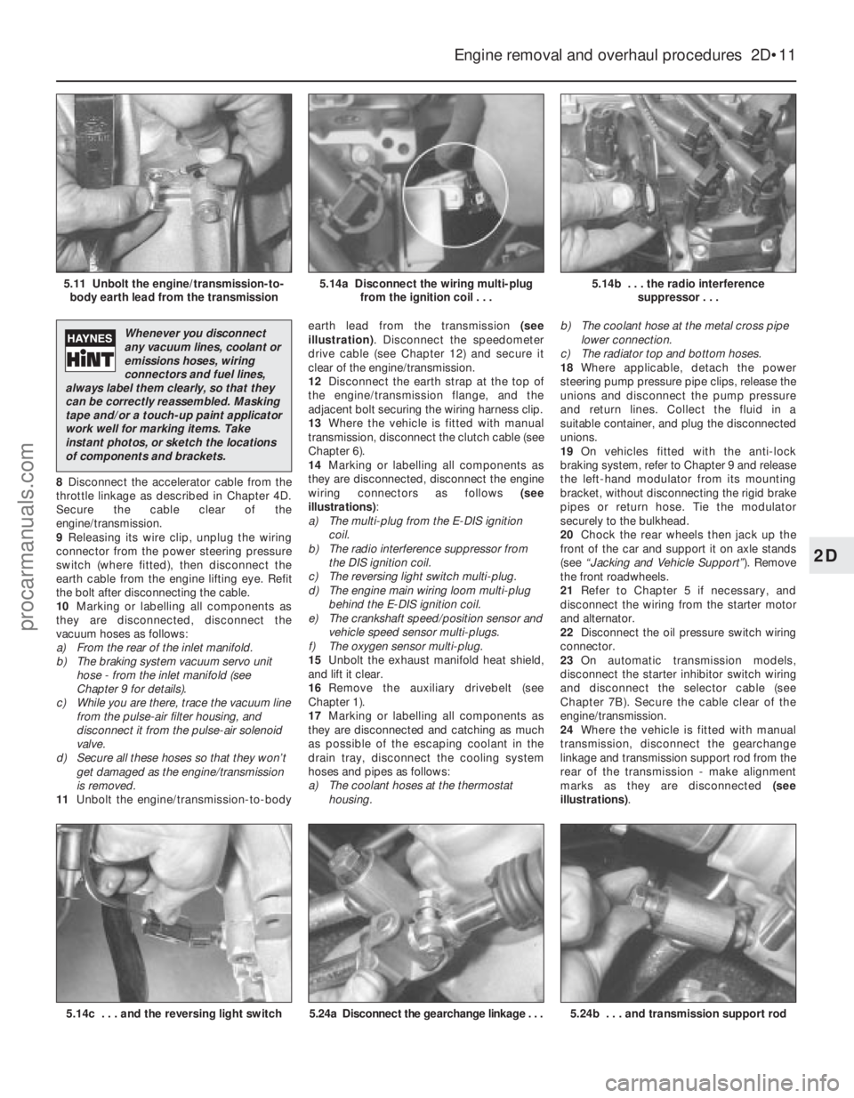
11 Unbolt the engine/transmission-to-body earth lead from the transmission
(see
illustration) . Disconnect the speedometer
drive cable (see Chapter 12) and secure it
clear of the engine/transmission.
12 Disconnect the earth strap at the top of
the engine/transmission flange, and the
adjacent bolt securing the wiring harness clip.
13 Where the vehicle is fitted with manual
transmission, disconnect the clutch cable (see
Chapter 6).
14 Marking or labelling all components as
they are disconnected, disconnect the engine
wiring connectors as follows (see
illustrations) :
a) The multi-plug from the E-DIS ignition
coil.
b) The radio interference suppressor from
the DIS ignition coil.
c) The reversing light switch multi-plug.
d) The engine main wiring loom multi-plug
behind the E-DIS ignition coil.
e) The crankshaft speed/position sensor and vehicle speed sensor multi-plugs.
f) The oxygen sensor multi-plug.
15 Unbolt the exhaust manifold heat shield,
and lift it clear.
16 Remove the auxiliary drivebelt (see
Chapter 1).
17 Marking or labelling all components as
they are disconnected and catching as much
as possible of the escaping coolant in the
drain tray, disconnect the cooling system
hoses and pipes as follows:
a) The coolant hoses at the thermostat housing. b)
The coolant hose at the metal cross pipe
lower connection.
c) The radiator top and bottom hoses.
18 Where applicable, detach the power
steering pump pressure pipe clips, release the
unions and disconnect the pump pressure
and return lines. Collect the fluid in a
suitable container, and plug the disconnected
unions.
19 On vehicles fitted with the anti-lock
braking system, refer to Chapter 9 and release
the left-hand modulator from its mounting
bracket, without disconnecting the rigid brake
pipes or return hose. Tie the modulator
securely to the bulkhead.
20 Chock the rear wheels then jack up the
front of the car and support it on axle stands
(see “Jacking and Vehicle Support” ). Remove
the front roadwheels.
21 Refer to Chapter 5 if necessary, and
disconnect the wiring from the starter motor
and alternator.
22 Disconnect the oil pressure switch wiring
connector.
23 On automatic transmission models,
disconnect the starter inhibitor switch wiring
and disconnect the selector cable (see
Chapter 7B). Secure the cable clear of the
engine/transmission.
24 Where the vehicle is fitted with manual
transmission, disconnect the gearchange
linkage and transmission support rod from the
rear of the transmission - make alignment
marks as they are disconnected (see
illustrations) .
Engine removal and overhaul procedures 2D•11
5.14b . . . the radio interference
suppressor . . .5.14a Disconnect the wiring multi-plugfrom the ignition coil . . .5.11 Unbolt the engine/transmission-to-body earth lead from the transmission
5.24b . . . and transmission support rod5.24a Disconnect the gearchange linkage . . .5.14c . . . and the reversing light switch
2D
1595Ford Fiesta Remake
Whenever you disconnect
any vacuum lines, coolant or
emissions hoses, wiring
connectors and fuel lines,
always label them clearly, so that they
can be correctly reassembled. Masking
tape and/or a touch-up paint applicator
work well for marking items. Take
instant photos, or sketch the locations
of components and brackets.
procarmanuals.com
http://vnx.su
Page 90 of 296
diameter from the bore measurement. If the
precision measuring tools shown are not
available, the condition of the pistons and
bores can be assessed, though not quite as
accurately, by using feeler gauges as follows.
Select a feeler gauge of thickness equal to the
specified piston-to-bore clearance, and slip it
into the cylinder along with the matching
piston. The piston must be positioned exactly
as it normally would be. The feeler gauge
must be between the piston and cylinder on
one of the thrust faces (at right-angles to the
gudgeon pin bore). The piston should slip
through the cylinder (with the feeler gauge in
place) with moderate pressure; if it falls
through or slides through easily, the clearance
is excessive, and a new piston will be
required. If the piston binds at the lower end
of the cylinder, and is loose toward the top,
the cylinder is tapered. If tight spots are
encountered as the piston/feeler gauge is
rotated in the cylinder, the cylinder is
out-of-round (oval).15 Repeat these procedures for the
remaining pistons and cylinder bores.
16 Compare the results with the
Specifications at the beginning of this
Chapter; if any measurement is beyond the
dimensions specified for that class (check the
piston crown marking to establish the class
of piston fitted), or if any bore measurement is
significantly different from the others
(indicating that the bore is tapered or oval),
the piston or bore is excessively-worn.
17 Worn pistons must be renewed; on some
engines, the pistons are available as Ford
replacement parts only as part of the
complete piston/connecting rod assembly.
See a Ford dealer or engine reconditioning
specialist for advice.
18 If any of the cylinder bores are badly
scuffed or scored, or if they are excessively-
worn, out-of-round or tapered, the usual
course of action would be to have the cylinder
block/crankcase rebored, and to fit new,
oversized, pistons on reassembly. See a Ford
dealer or engine reconditioning specialist for
advice.
19 If the bores are in reasonably good
condition and not excessively-worn, then it
may only be necessary to renew the piston
rings.
20 If this is the case, the bores should be
honed, to allow the new rings to bed in
correctly and provide the best possible seal.
Honing is an operation that will be carried out
for you by an engine reconditioning specialist.
21 After all the machining operations have
been carried out, the entire block/crankcase
must be washed very thoroughly with warm
soapy water to remove all traces of abrasive
grit produced during the machining
operations. When completely clean, rinse it
thoroughly and dry it, then lightly oil all
exposed machined surfaces to prevent
rusting.
22 The cylinder block/crankcase should now
be completely clean and dry, with all components checked for wear or damage,
and repaired or overhauled as necessary.
Refit as many ancillary components as
possible, for safekeeping. If reassembly is not
to start immediately, cover the block with a
large plastic bag to keep it clean.
14 Main and big-end bearings
-
inspection
4
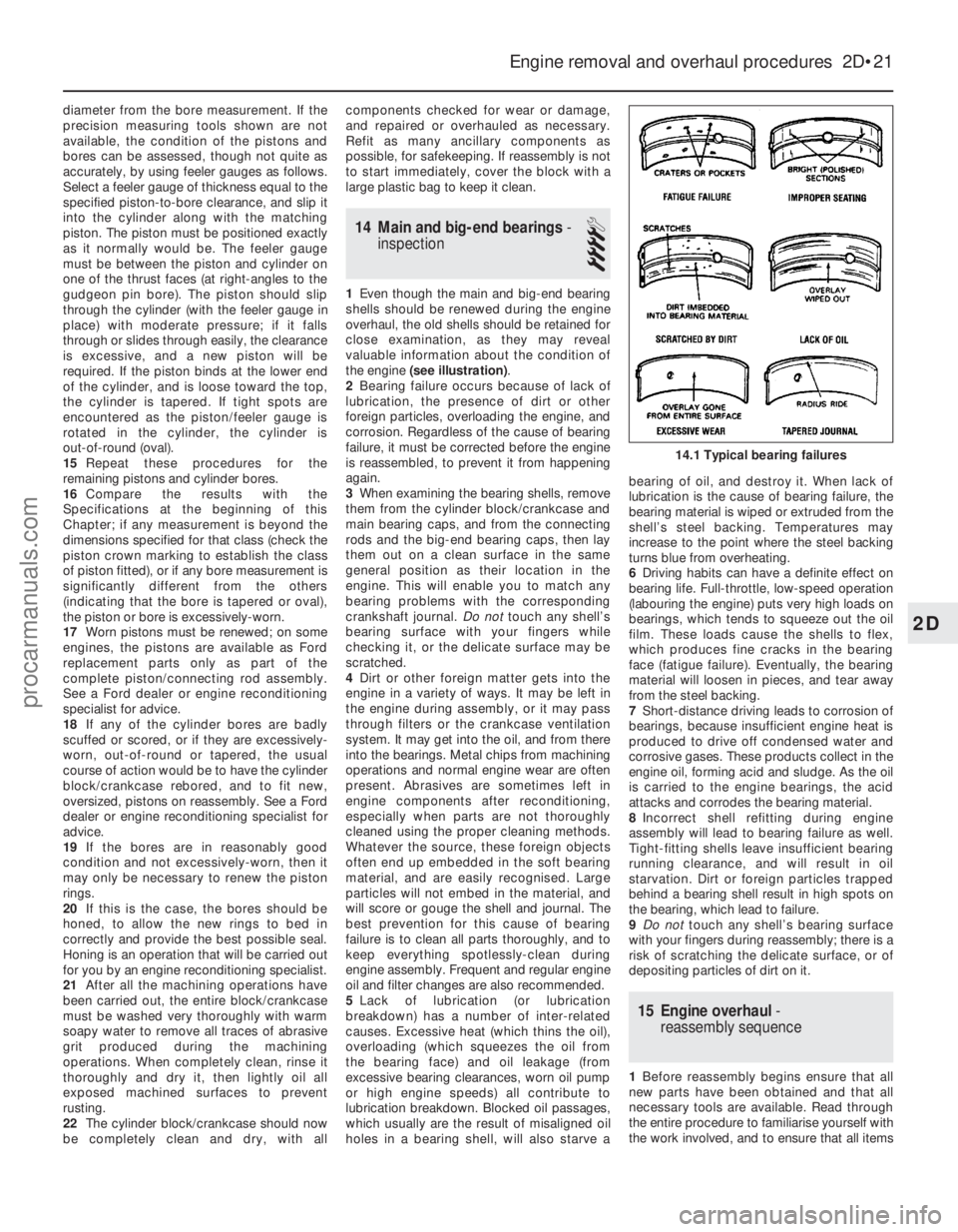
1 Even though the main and big-end bearing
shells should be renewed during the engine
overhaul, the old shells should be retained for
close examination, as they may reveal
valuable information about the condition of
the engine (see illustration) .
2 Bearing failure occurs because of lack of
lubrication, the presence of dirt or other
foreign particles, overloading the engine, and
corrosion. Regardless of the cause of bearing
failure, it must be corrected before the engine
is reassembled, to prevent it from happening
again.
3 When examining the bearing shells, remove
them from the cylinder block/crankcase and
main bearing caps, and from the connecting
rods and the big-end bearing caps, then lay
them out on a clean surface in the same
general position as their location in the
engine. This will enable you to match any
bearing problems with the corresponding
crankshaft journal. Do nottouch any shell’s
bearing surface with your fingers while
checking it, or the delicate surface may be
scratched.
4 Dirt or other foreign matter gets into the
engine in a variety of ways. It may be left in
the engine during assembly, or it may pass
through filters or the crankcase ventilation
system. It may get into the oil, and from there
into the bearings. Metal chips from machining
operations and normal engine wear are often
present. Abrasives are sometimes left in
engine components after reconditioning,
especially when parts are not thoroughly
cleaned using the proper cleaning methods.
Whatever the source, these foreign objects
often end up embedded in the soft bearing
material, and are easily recognised. Large
particles will not embed in the material, and
will score or gouge the shell and journal. The
best prevention for this cause of bearing
failure is to clean all parts thoroughly, and to
keep everything spotlessly-clean during
engine assembly. Frequent and regular engine
oil and filter changes are also recommended.
5 Lack of lubrication (or lubrication
breakdown) has a number of inter-related
causes. Excessive heat (which thins the oil),
overloading (which squeezes the oil from
the bearing face) and oil leakage (from
excessive bearing clearances, worn oil pump
or high engine speeds) all contribute to
lubrication breakdown. Blocked oil passages,
which usually are the result of misaligned oil
holes in a bearing shell, will also starve a bearing of oil, and destroy it. When lack of
lubrication is the cause of bearing failure, the
bearing material is wiped or extruded from the
shell’s steel backing. Temperatures may
increase to the point where the steel backing
turns blue from overheating.
6
Driving habits can have a definite effect on
bearing life. Full-throttle, low-speed operation
(labouring the engine) puts very high loads on
bearings, which tends to squeeze out the oil
film. These loads cause the shells to flex,
which produces fine cracks in the bearing
face (fatigue failure). Eventually, the bearing
material will loosen in pieces, and tear away
from the steel backing.
7 Short-distance driving leads to corrosion of
bearings, because insufficient engine heat is
produced to drive off condensed water and
corrosive gases. These products collect in the
engine oil, forming acid and sludge. As the oil
is carried to the engine bearings, the acid
attacks and corrodes the bearing material.
8 Incorrect shell refitting during engine
assembly will lead to bearing failure as well.
Tight-fitting shells leave insufficient bearing
running clearance, and will result in oil
starvation. Dirt or foreign particles trapped
behind a bearing shell result in high spots on
the bearing, which lead to failure.
9 Do not touch any shell’s bearing surface
with your fingers during reassembly; there is a
risk of scratching the delicate surface, or of
depositing particles of dirt on it.
15 Engine overhaul -
reassembly sequence
1 Before reassembly begins ensure that all
new parts have been obtained and that all
necessary tools are available. Read through
the entire procedure to familiarise yourself with
the work involved, and to ensure that all items
Engine removal and overhaul procedures 2D•21
14.1 Typical bearing failures
2D
1595Ford Fiesta Remakeprocarmanuals.com
http://vnx.su
Page 94 of 296
Plastigauge to the scale printed on the
Plastigauge envelope, to obtain the running
clearance (see illustration 17.15) . Compare it
to the Specifications, to make sure the
clearance is correct.
14 If the clearance is not as specified, seek
the advice of a Ford dealer or similar engine
reconditioning specialist - if the crankshaft
journals are in good condition it may be
possible simply to renew the shells to achieve
the correct clearance. If this is not possible,
the crankshaft must be reground by a
specialist, who can also supply the necessary
undersized shells. First though, make sure
that no dirt or oil was trapped between the
bearing shells and the connecting rod or cap
when the clearance was measured. Also,
recheck the crankpin diameter. If the
Plastigauge was wider at one end than the
other, the crankpin journal may be tapered.
15 Carefully scrape all traces of the
Plastigauge material off the journal and the
bearing surface. Be very careful not to scratch
the bearing - use your fingernail or the edge of a credit card.
Final piston/connecting rod
refitting
16 Make sure the bearing surfaces are
perfectly clean, then apply a uniform layer of
clean molybdenum disulphide-based grease,
engine assembly lubricant, or clean engine oil,
to both of them. You’ll have to push the piston
into the cylinder to expose the bearing surface
of the shell in the connecting rod.
17 Slide the connecting rod back into place
on the crankpin (big-end) journal, refit the big-
end bearing cap, and then tighten the bolts as
described above.
18 Repeat the entire procedure for the
remaining piston/connecting rod assemblies.
19 The important points to remember are:
a) Keep the backs of the bearing shells and the recesses of the connecting rods and
caps perfectly clean when assembling
them.
b) Make sure you have the correct
piston/rod assembly for each cylinder -
use the etched cylinder numbers to
identify the front-facing side of both the
rod and its cap.
c) The arrow on the piston crown must face the timing belt/chain end of the engine.
d) Lubricate the cylinder bores with clean
engine oil.
e) Lubricate the bearing surfaces when refitting the big-end bearing caps after the
running clearance has been checked. 20
After all the piston/connecting rod
assemblies have been properly installed,
rotate the crankshaft a number of times by
hand, to check for any obvious binding.
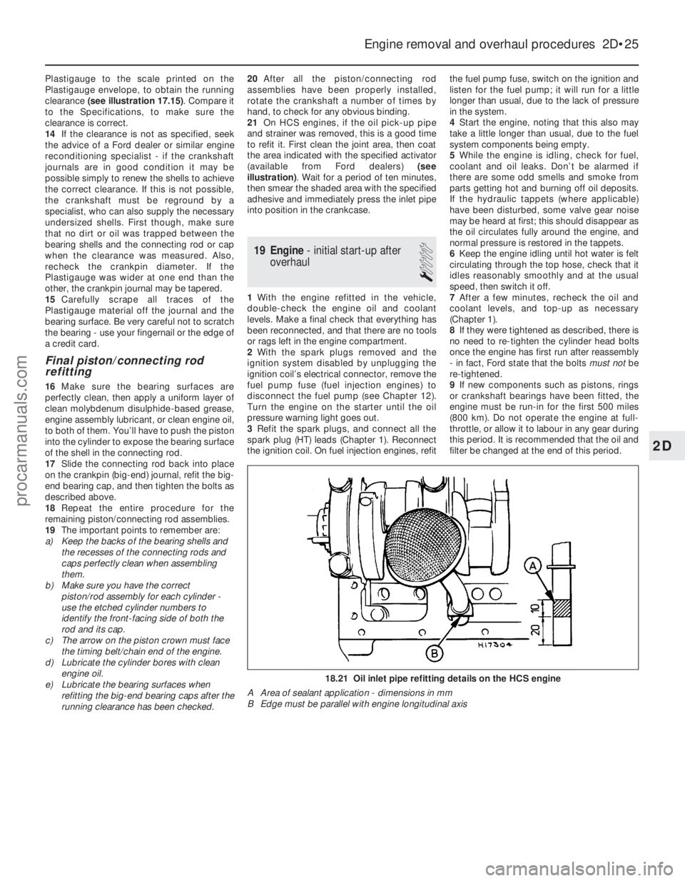
21 On HCS engines, if the oil pick-up pipe
and strainer was removed, this is a good time
to refit it. First clean the joint area, then coat
the area indicated with the specified activator
(available from Ford dealers) (see
illustration) . Wait for a period of ten minutes,
then smear the shaded area with the specified
adhesive and immediately press the inlet pipe
into position in the crankcase.
19 Engine - initial start-up after
overhaul
1
1 With the engine refitted in the vehicle,
double-check the engine oil and coolant
levels. Make a final check that everything has
been reconnected, and that there are no tools
or rags left in the engine compartment.
2 With the spark plugs removed and the
ignition system disabled by unplugging the
ignition coil’s electrical connector, remove the
fuel pump fuse (fuel injection engines) to
disconnect the fuel pump (see Chapter 12).
Turn the engine on the starter until the oil
pressure warning light goes out.
3 Refit the spark plugs, and connect all the
spark plug (HT) leads (Chapter 1). Reconnect
the ignition coil. On fuel injection engines, refit the fuel pump fuse, switch on the ignition and
listen for the fuel pump; it will run for a little
longer than usual, due to the lack of pressure
in the system.
4
Start the engine, noting that this also may
take a little longer than usual, due to the fuel
system components being empty.
5 While the engine is idling, check for fuel,
coolant and oil leaks. Don’t be alarmed if
there are some odd smells and smoke from
parts getting hot and burning off oil deposits.
If the hydraulic tappets (where applicable)
have been disturbed, some valve gear noise
may be heard at first; this should disappear as
the oil circulates fully around the engine, and
normal pressure is restored in the tappets.
6 Keep the engine idling until hot water is felt
circulating through the top hose, check that it
idles reasonably smoothly and at the usual
speed, then switch it off.
7 After a few minutes, recheck the oil and
coolant levels, and top-up as necessary
(Chapter 1).
8 If they were tightened as described, there is
no need to re-tighten the cylinder head bolts
once the engine has first run after reassembly
- in fact, Ford state that the bolts must notbe
re-tightened.
9 If new components such as pistons, rings
or crankshaft bearings have been fitted, the
engine must be run-in for the first 500 miles
(800 km). Do not operate the engine at full-
throttle, or allow it to labour in any gear during
this period. It is recommended that the oil and
filter be changed at the end of this period.
Engine removal and overhaul procedures 2D•25
18.21 Oil inlet pipe refitting details on the HCS engine
A Area of sealant application - dimensions in mm
B Edge must be parallel with engine longitudinal axis
2D
1595Ford Fiesta Remakeprocarmanuals.com
http://vnx.su