1988 PONTIAC FIERO lock
[x] Cancel search: lockPage 90 of 1825
R-4 AIR 60NDlVlONBNG COMPRESSOR OVERHAUL l Dl-1 l
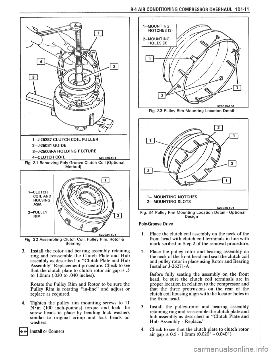
1-J-25287 CLUTCH COIL PULLER
2-5-25031 GUIDE
3-J-25Q88-A HOLDING F IXVUWE
4-CLUTCH COl b 520023.1 DI
Fig. 3 1 Removing Poly-Groove Clutch Coil (Optional
Method)
1-CLUTCH COIL AND HOUSING
ASM.
2-PULLEY
RIM
Fig. 32 Assembling Clutch Coil, Pulley Rim, Rotor & Bearing
3. Install the rotor and bearing assembly retaining
ring and reassemble the Clutch Plate and Hub
assenibly as described in "Clutch Plate and Hub
Assembly"
Repllacement procedure. Check to see
that the clutch plate to clutch rotor air gap is
.5
to l.Omm (.020 to .040 inches).
Rotate the Pulley Rim and Rotor to be sure the
Pulley Rim is rotating "in-line" and adjust or
replace as required.
4. Tighten the pulley rim mounting screws to 11
Nom (100 inch-pounds) torque and lock the
screw heads in place by bending lock washers
similar to original
crimp and lock bends on
washers.
Fig. 33 Pulley Rim Mounting Location Detail
Ill
1- MOUNTING NOTCHES
2- MOUNTING SLOTS
Fig.
34 Pulley Rim Mounting Location Detail - Optional
Design
Poly-Groove Drive
1. Place
the clutch coil assembly on the neck of the
front head with clutch coil terminals in line with
mark scribed in Step
2 of the removal procedure.
2. Place the pulley rotor and bearing assembly on
the neck of the front head and seat the clutch coil
and pulley rotor in place using Rotor and Bearing
Installer
J-2627 1 -A.
Before fully seating the assembly on the front
head, be sure the clutch coil terminals are in
proper location in relation to the compressor and
that the three protrusions on the rear of the
clutch coil housing align with the locator holes in
the front head.
3. Install the pulley-rotor and bearing assembly
retaining ring and reassemble the clutch plate and
hub assembly as described in "Clutch Plate and
Hub Assembly
- Replace."
Install or Gsns~eet 4. Check
to see that the clutch plate to clutch rotor
air gap is 0.5
- f.Omm (0.020" - 0.040").
Page 91 of 1825
4 Dl-I 2 R-4 AIR CONDITIONING COMPRESSOR OVERHAUL
MAJOR REPAIR PROCEDURES
Service repair procedures to the
Compressor Shaft Seal,
Pressure Relief Valve
or disassembly
of the Internal Compressor
Cylinder and Shaft Assembly are considered
"MAJOR" SINCE THE REFRIGERATION
SYSTEM MUST BE DISCHARGED,
EVACUATED AND RECHARGED to complete
service and/or because major internal
operating and sealing components of the
compressor are being disassembled and
serviced.
When replacing the shaft seal assembly or
pressure relief valve, even if the compressor remains on
the vehicle during the operation, it will be necessary to
discharge the system of refrigerant (see Section
1B).
Other than clutch repair procedures, the same holds
true for any disassembly of the compressor.
If the compressor shell, front head or cylinder
and shaft assembly are to be serviced or replaced, the
oil in the compressor must be drained, measured and
replaced (see Section
1B) to determine addition of
proper oil quantity to new assembly.
A clean workbench, preferably covered with a
sheet of clean paper, orderliness in the work area and
a place for all parts being removed and replaced is of
great importance, as is the use of the proper, clean
service tools.
NOTICE: Any attempt to use make-shift or
inadequate equipment may result in damage
and/or improper compressor operation.
All parts required for servicing the internal
compressor are protected by a preservation process and
packaged in a manner which will eliminate the
necessity of cleaning, washing or flushing of the parts.
The parts can be used in the internal assembly just as
they are removed from the service package.
Seals and
protective packaging should be left in tact un
ti1 just
prior to installation.
SI-IAFT SEAL
Fig. 35 thru 40
Shaft Seal Design
The shaft seal is a one piece design.
Seal Leak Detection
A shaft seal should not be changed because of an
oil-line on the hood insulator. The Seal is designed to
seep some oil for lubrication purposes. Only change a
Shaft Seal when a leak is detected by evidence of oil
sprayed in large amounts and then only after actual
refrigerant leakage is found by using an approved leak
Detector such as J-29547 or equivalent.
Should an R-4 compressor shaft seal ever have to
be replaced, the accumulator in this R-4 system must
also be removed from the vehicle. The oil in the
accumulator then must be drained, measured and
replaced according to the directions in Section
1B to
determine oil loss.
On-Car
Remove
or Disconnect
1. Discharge A/C system
2. Loosen and reposition compressor in mounting
brackets
3. Clutch Plate and Hub assembly
4. Shaft seal seat retainer ring, using Snap Ring
Pliers J-5403-A
5. Thoroughly clean inside of compressor neck area
and O-ring groove surrounding the shaft, the
exposed portion of the seal seat and the shaft
itself. Any dirt or foreign material getting into
compressor may cause damage.
6. Remove Lip Seal:
e Fully engage the knurled tangs of Seal
Remover-Installer J-23 128-A into the
recessed portion of the Seal by turning the
handle clockwise. Remove the Seal from the
compressor with a rotary-pulling motion.
Discard the Seal. The handle must be
hand-tightened securely. Do not use a
wrench or pliers.
7. Discard the seal seat O-ring from the compressor
neck using 0-Ring Remover J-9553-01.
8. Recheck the shaft and inside of the compressor
neck and O-ring groove for dirt or foreign
material and be sure these areas are perfectly
clean before installing new parts.
Inspection
Seals should not be reused. Always use a new
specification service seal kit on rebuild. Care should be
taken to prevent damage to the lip of the one piece seal.
Make sure that the Seal Seat and Seal Lip are free of
lint and dirt that could damage the seal surface or
prevent sealing.
On-Car
Install
or Connect
1. Dip
the new seal O-ring in clean 525 viscosity
refrigerant oil and assemble onto 0-Ring
Installer J-33011.
2. Insert
the 0-Ring Installer
5-3301 1 completely
down into the compressor neck until the Installer
"bottoms." Lower the moveable slide of the
0-Ring Installer to release the 0-Ring into the
seal seat O-ring lower groove. (The compressor
neck top groove is for the shaft seal retainer ring.)
Rotate the Installer to seat the O-ring and remove
the Installer.
3. Prepare Lip Seal:
Assemble seal to Seal Installer J-23128-A,
by turning handle clockwise, and then push
Seal Protector J-34614, into seal lip. The
stamped steel case side of the lip seal must
be engaged with knurled tangs of installer so
that flared-out side of lip seal is facing and
installed towards the compressor.
4. Install Lip Seal:
Page 95 of 1825
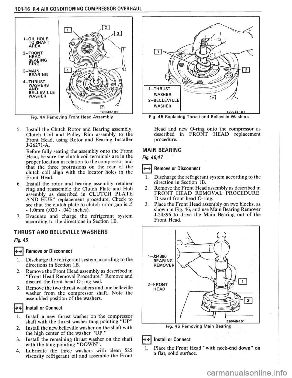
1D1-16 R-4 AIR CONDITIONING COMPRESSOR OVERHAUL
BELLEVl LLE
2-BELLEVI
LLE
Fig. 44 Removing Front Head Assembly Fig. 45 Replacing Thrust
and Belleville Washers
5. I~stall the Clutch Rotor and Bearing assembly,
Clutch Coil and Pulley Rim assembly to the
Front Head, using Rotor and Bearing Installer
J-2627 1-A.
Before fully seating the assembly onto the Front
Head, be sure the clutch coil terminals are in the
proper location in relation to the compressor and
that the three protrusions on the rear of the
clutch coil align with the locator holes in the
Front Head.
6. Install the rotor and bearing assembly retainer
ring and reassemble the Clutch Plate and Hub
assembly as described in CLUTCH PLATE
AND HUB" replacement procedure. Check to
see that the clutch plate to clutch rotor gap is
.5
- 1.Omm (.020 - .040 inches).
7. Evacuate and charge the refrigerant system
according to the directions in Section
1B.
THRUST AND BELLEVILLE WASHERS
Fig. 45
Remove or Disconnect
1. Discharge the refrigerant system according to the
directions in Section
1B.
2. Remove
the Front Head assembly as described in
"Front Head Removal Procedure." Remove and
discard the front head O-ring seal.
3. Remove the two thrust washers and one belleville
washer from the compressor shaft. Note the
assembled position of the washers.
Install or Connect
1. Install a new thrust washer on the compressor
shaft with the thrust washer tang pointing "UP"
2. Install the new belleville washer on the shaft with
the high center of the washer "UP." Head
and new O-ring onto the compressor as
described in FRONT HEAD replacement
procedure.
MAIN BEARING
Fig. 46,47
Remove or Disconnect
1. Discharge the refrigerant system according to the
direction in Section
1B.
2. Remove the Front Head assembly as described in
FRONT HEAD REMOVAL PROCEDURE.
Discard front head O-ring.
3. Place the Front Head assembly on two blocks, as
shown in Fig. 46, and use Main Bearing Remover
J-24896 to drive the Main Bearing out of the
Front Head.
Fig. 46 Removing Main Bearing
-
3. Install the remaining thrust washer on the shaft Install or Connect
with the tang pointing "DOWN".
4. Lubricate the three washers with clean 525 1. Place the Front Head "with neck-end down" on
viscosity refrigerant oil and assemble the Front a
flat, solid surface.
Page 96 of 1825
R-4 AIR CONDITIONING COMPRESSOR OVERHAUL 1 Dl-17
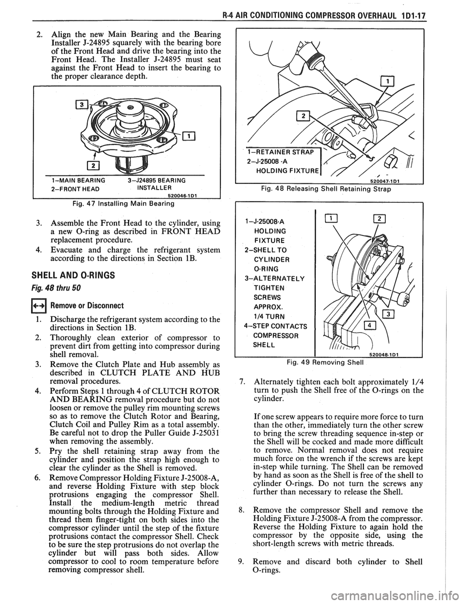
2. Align
the new Main Bearing and the Bearing
Installer
5-24895 squarely with the bearing bore
of the Front Head and drive the bearing into the
Front Head. The Installer J-24895 must seat
against the Front Head to insert the bearing to
the proper clearance depth.
Fig. 47 Installing Main Bearing
3. Assemble the Front Head to the cylinder, using
a new O-ring as described in FRONT HEAD
replacement procedure.
4. Evacuate and charge the refrigerant system
according to the directions in Section
1B.
SHELL AND O-RINGS
Fig. 48 thru 50
Remove or Disconnect
1. Discharge the refrigerant system according to the
directions in Section
1B.
2. Thoroughly clean exterior of compressor to
prevent dirt from getting into compressor during
shell removal.
3. Remove the Clutch Plate and Hub assembly as
described in CLUTCH PLATE AND HUB
removal procedures.
4. Perform Steps 1 through 4 of CLUTCH ROTOR
AND BEARING removal procedure but do not
loosen or remove the pulley rim mounting screws
so as to remove the Clutch Rotor and Bearing,
Clutch Coil and Pulley Rim as a total assembly.
Be careful not to drop the Puller Guide J-25031
when removing the assembly.
5. Pry the shell-retaining strap away from the
cylinder and position the strap high enough to
clear the cylinder as the Shell is removed.
6. Remove Compressor Holding Fixture J-25008-A,
and reverse Holding Fixture with step block
protrusions engaging the compressor Shell.
Install the medium-length metric thread
mounting bolts through the Holding Fixture and
thread them finger-tight on both sides into the
compressor cylinder until the step of the fixture
protrusions contact the compressor Shell. Check
to be sure the step protrusions do not overlap the
cylinder but will pass both sides. Allow
compressor to cool to room temperature before
removing compressor shell.
2-J-25008 -A
HOLDING FIXTURE
Fig. 48 Releasing Shell Retaining Strap
HOLDING FIXTURE
2-SHELL TO
CYLINDER
O-RING
3-ALTERNATELY
TIGHTEN
SCREWS
APPROX.
114 TURN
4-STEP CONTACTS
COMPRESSOR
SHELL
Fig. 49 Removing Shell
7. Alternately tighten each bolt approximately 1/4
turn to push the Shell free of the O-rings on the
cylinder.
If one screw appears to require more force to turn
than the other, immediately turn the other screw
to bring the screw threading sequence in-step or
the Shell will be cocked and made more difficult
to remove. Normal removal does not require
much force on the wrench if the screws are kept
in-step while turning. The Shell can be removed
by hand as soon as the Shell is free of the shell to
cylinder O-rings. Do not turn the screws any
further than necessary to release the Shell.
8. Remove the compressor Shell and remove the
Holding Fixture J-25008-A from the compressor.
Reverse the Holding Fixture to again hold the
compressor by the opposite side, using the
short-length screws with metric threads.
9. Remove and discard both cylinder to Shell
O-rings.
Page 100 of 1825
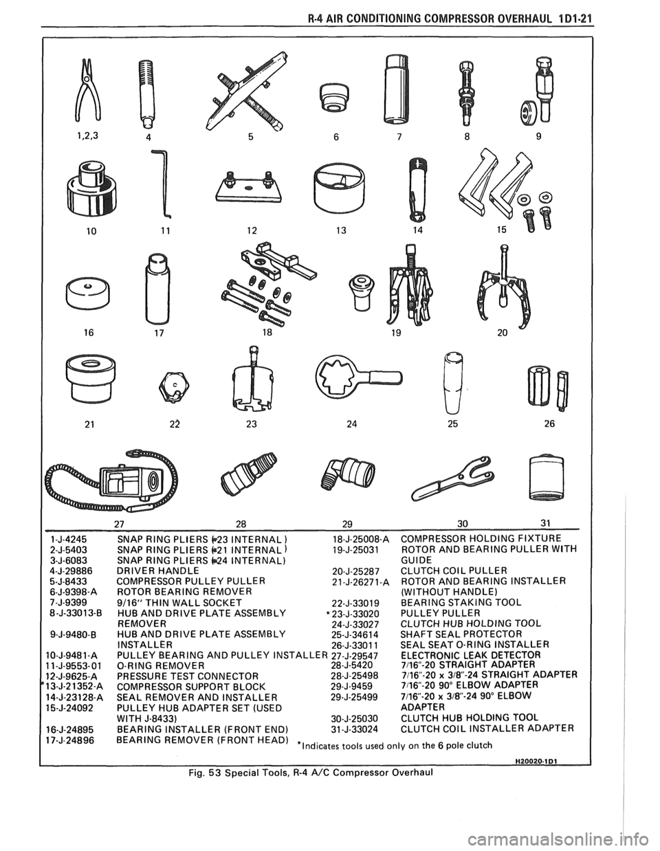
R-4 AIR CONDITIONING COMPRESSOR OVERHAUL 1 Dl-21
SNAP RING PLIERS b23 INTERNAL ) 18-J-25008-A COMPRESSOR HOLDING FIXTURE
SNAP
RING PLIERS @21 INTERNAL) 19-J-25031 ROTOR
AND BEARING PULLER WITH SNAP RING PLIERS 44424 INTERNAL)
GUIDE
DRIVER HANDLE 20-J-25287 CLUTCH COIL PULLER
COMPRESSOR PULLEY PULLER 21-J-26271.A ROTOR AND BEARING INSTALLER
ROTOR BEARING REMOVER (WITHOUT HANDLE)
9/16"
THIN WALL SOCKET
22-J-33019 BEARING STAKING TOOL
HUB AND DRIVE PLATE ASSEMBLY "23-J-33020 PULLEY PULLER
REMOVER 24-J-33027 CLUTCH HUB HOLDING TOQL
HUB AND DRIVE PLATE ASSEMBLY 25-J-34614 SHAFT SEAL PROTECTOR
INSTALLER 26-J-33011 SEAL SEAT O-RING INSTALLER
PULLEY BEARING AND PULLEY INSTALLER
27-J-29547 ELECTRONIC LEAK DETECTOR
O-RING REMOVER 28-J-5420 7116"-20 STRAIGHT ADAPTER
PRESSURE TEST CONNECTOR 28-J-25498 7116"-20 x 3/8-24 STRAIGHT ADAPTER
COMPRESSOR SUPPORT BLOCK 29-J-9459 7116"-20 90" ELBOW ADAPTER
SEAL REMOVER AND INSTALLER 29-J-25499 7/16-20 x 318"-24 90" ELBOW
PULLEY HUB ADAPTER SET (USED ADAPTER
WITH
J-8433) 30-J-25030 CLUTCH HUB HOLDING TOOL
BEARING INSTALLER (FRONT END) 31-J-33024 CLUTCH COIL INSTALLER ADAPTER
HEAD) "Indicates tools used only on the 6 pole clutch
Fig.
53 Special Tools, R-4 A/C Compressor Overhaul
Page 103 of 1825
2B-2 BUMPERS
REAR BUMPER FASCIA
Removal
Place a jack stand under fascia before removing
bolts to prevent it from dropping down when fascia
attaching bolts are removed. Fascia will pivot on the
opposite end when one end is disconnected. Do not
rotate energy absorber any more than necessary to
align mounting holes.
1. Remove fascia attaching bolts and fascia to
fender attaching screws on right and left side, and
remove fascia and spacers.
2. If energy absorber is to be replaced, remove the
bolts and nuts from the front of the unit and the
nut from the stud at the rear. The stud at the rear
of the absorber is attached to a bracket in the
frame. Remove the bolt holding this bracket in
the frame to remove the absorber.
Installation
1. Install energy absorber if removed.
2. Support fascia during installation to prevent
rotation of energy absorbers.
3. Install spacers and bolts at fascia to energy
absorber brackets.
4. Install fascia to fender attaching screws.
5. Check for proper clearance.
6. If adjustment is required to align the fascia, use
shims as necessary. Vertical and lateral
adjustment can be made at slots in fascia and
absorber brackets. Torque all bolts and nuts. (See
Specifications.)
FRONT BUMPER
Removal
1. Remove
front end fascia as shown in Section 2C.
2. Remove bumper barlenergy absorber assembly
from body.
3. If energy absorber must be replaced, drill out pop
rivets, and install new absorber with nuts, bolts,
and locking washers.
4. To install, reverse above procedure.
REAR BUMPER
Removal
1. Remove left hand rear quarter trim panel.
2. Remove right hand rear quataer trim panel.
3. Remove spare tire assembly.
4. Remove rear center trim panel.
5. Remove right tail light assembly.
6. Remove left tail light assembly.
7. Remove tail light center piece.
8. Remove bumper cover lower retainers.
9. Remove right-side bumper cover fasteners from
inside of compartment.
10. Remove left side bumper cover fasteners from
inside of compartment.
11. Remove bumper cover upper retainers.
12. Remove cover.
13. To dissasemble impact bar, proceed as follows:
a. Remove bolts attataching impact bar to
rear end panel.
b. Remove rivets retaining pad to impact
bar.
14. To install, reverse above procedure.
BUMPER ENERGY ABSORBING UNITS
The absorbing capability for both front and rear
bumper systems is achieved through two energy
absorbing devices in each bumper. These units convert
the energy of an impact into heat and restoration. The
energy absorbing device consists of two main
subassemblies: the piston tube assembly and the
cylinder tube assembly. The piston tube assembly is
filled with an inert gas under pressure and consists of
a bumper bracket, piston tube, orifice, seal, piston seal,
piston, and stop-ring. The cylinder tube assembly is
filled with a hydraulic fluid and consists of a frame
bracket, cylinder tube, mounting stud, and metering
pin.
Upon impact, as the energy absorber is collapsed,
the hydraulic fluid in the cylinder tube is forced into
the piston tube through the orifice. The metering pin
controls the rate at which this fluid passes from the
cylinder tube through the orifice and into the piston
tube. This controlled passage of fluid provides the
energy absorbing action.
The hydraulic fluid that is forced from the
cylinder tube into the piston tube displaces the floating
piston, compressing the gas behind the floating piston.
After impact, the pressure of the compressed gas
behind the floating piston forces the hydraulic fluid
back into the cylinder tube assembly, extending the
unit to its normal position.
Some front and rear bumpers (J and
F Models)
use a plastic honeycomb pad energy absorber (except
J wagon rear bumper). This energy absorber will
compress on impact, and both the energy absorber and
the urethane fascia will return to their original shape.
The energy absorber pad has no moving parts.
The J wagon rear bumper system uses a hydraulic
energy absorbing unit, more commonly known as a
"minisorber".
TESTING FRONT OR REAR ENERGY
ABSORBER OPERATION
The right and left energy absorbing devices are to
be diagnosed separately. The following checks are to be
made on each unit:
1. Leakage
Some oil wetting may be visible due to the grease
packed in the crimp recess. Therefore, a stain or trace
of oil on the piston tube near the crimp is normal.
However, if oil is dripping continuously from the crimp
or the stud end of the unit, a leak is indicated and the
unit should be replaced.
Page 109 of 1825
26-2 CHASSIS SHEET METAL
TO RAISE OR LOWER THE FRONT comers
for proper alignment, proceed as follows:
1. Close hood firmly.
2. Determine the amount of adjustment necessary.
3. Open hood.
4. Raise or lower the adjustable hood bumpers as
required.
FORE AND APT adjustment can be accom-
plished as follows:
1. Loosen hinge to fender attaching screws.
Remove or Disconnect
Open hood.
Scribe line on hood inner panel and fender panel
to indicate original hinge position.
Block hood on side where hinge is to be
removed.
Prop hood open.
Remove hinge-to-hood attaching screws and
hinge-to-fender attaching screws.
Carefully remove hinge and strut assembly.
- -
2. Reposition hinge assembly. install or Conned 3. Tighten hinge to fender attaching screws to
specifications. 1. Mount new hinge on fender using scribed line
4. If necessary, repeat procedure on opposite side for location,
and tighten attaching screws.
of hood. 2.
Position hinge to hood using scribed line for
location, install attaching screws and tighten.
3. Carefully close hood and check for proper
- - alignment.
4. If hood is misaligned, measure amount of
mis-
Figure 7
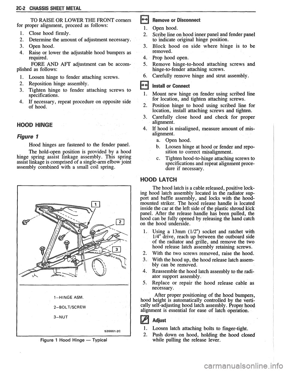
Hood hinges are fastened to the fender panel.
The hold-open position is provided by a hood
hinge spring assist linkage assembly. This spring
assist linkage is comprised of a
single-am elbow joint
assembly combined with a small coil spring.
1-HINGE ASM.
2-BOLT/SCREW
Figure 1 Hood Hinge - Typical
alignment.
a. Open hood.
b. Loosen hinge at hood or fender and repo-
sition to correct misalignment.
c. Tighten hood-to-hinge attaching screws to
specifications and repeat alignment proce-
dure if necessary.
HOOD L14TCI-I
The hood latch is a cable released, positive lock-
ing hood latch assembly located in the radiator sup-
port and baffle assembly, and locks with the
hood-
mounted striker. The hood release handle is located
inside the car at the left side of the plastic shroud kick
panel. After the release handle has been pulled, the
hood can be fully opened by releasing the hand catch
on the hood underside.
1. Using a
13mrn (112") socket and ratchet with
114" drive, reach up between the outboard side
of the radiator and grille, and remove the two
hood release latch assembly retaining screws.
2. With the two screws removed, raise the hood.
3. With the hood up, the hood release latch assem-
bly can be removed.
4. Reassemble the hood latch assembly to the radi-
ator support assembly.
5. Replace or repair the hood release cable as
necessary.
After proper positioning of the hood bumpers,
hood height is automatically controlled by the verti-
cally self-adjusting hood latch assembly. Proper hood
alignment is essential for ease of latch operation.
Adjust
1. Loosen latch attaching bolts to finger-tight.
2. Push down on hood, holding the hood closed
while pulling the release lever.
Page 114 of 1825
CHASSIS SHEET METAL 2@-7
3. During the above flash time period (1 to 10 min-
utes), apply appropriate "conventional" interior acrylic lacquer color as required and allow
painted part to dry for
4 to 5 hours before install-
ing on car.
RlGlD OW HARD ABS PMS"TIC PARTS
Rigid or hard ABS plastic requires no primer.
"Conventional" interior acrylic lacquers adhere satis-
factorily to hard ABS plastics.
Procedure
1. Wash part thoroughly with a cleaning solvent
(Acrylic-Clean, Pre-Kleano, Prep-Sol or equiv-
alent) to remove any dirt or grease.
2. Apply appropriate "conventional" interior
acrylic lacquer color. Apply only sufficient
color for proper hiding to avoid washout of
"grain" effect.
3. Allow to dry and then install part.
VINYL AND FLEXIBLE (Son) ABS
PLASTIC PARTS
The outer cover or skin material of "flexible"
instrument panel cover (pad) assemblies is made of an
ABSIPVC plastic blend. The same is true of many
"padded" door trim assemblies. The soft cushion pad-
ding under the I.P. skin is urethane foam plastic. The
most widely used
"flexible" vinyls (poly vinyl chlo-
ride)
are coated fabrics, such as used in seat trim,
some door trim assemblies, molded headlining panels
and sun visors. Most head rests are "flexible" vinyls.
Examples of "hard vinyls are: door and front seat
back assist handles and coat hooks.
The paint system of vinyl and flexible ABS
plastic involves the use of interior "vinyl" color and a
clear vinyl top coat.
Procedure
1. Wash part thoroughly with a vinyl cleaning and
preparation solvent ("Vinyl Press"
- Ditzler,
"Vinyl Prep Conditioner"
- Detroit Autobody
or equivalent) to remove greasy film or silicone.
Wipe off cleaner while still wet with clean,
lint-
free cloth.
2. Immediately after wiping face dry, apply inte-
rior "vinyl" color in wet coats allowing suffi-
cient flash time between coats (see label
directions on can). Use proper "vinyl" color as
designated by interior trim combinations. Apply
only sufficient color for proper hiding to avoid
washout of "grain" effect. No primer or
primer-
sealer is required.
3. Before the final vinyl color coat has dried, apply
two coats of clear vinyl top coat spray (instru-
ment panels will require the "nonglare" clear top
coat). Do not allow the first spray coat to com-
pletely dry before spraying on the second. Use
top coat with appropriate gloss level to match adjacent similar components. This
clear coat is
necessary to control the gloss requirement and
prevent
'tracking" (rubbing-off) of the color
coat after drying.
4. Allow to dry according to label directions before
installing part.
ON-VEHICLE SERVICE
CONCEALED HEADLIGHTS
The concealed headlights used on this model are
electrically operated. When the headlights are turned
on, solid state circuitry activates the actuators. This
same circuitry senses when the actuators stop moving
and removes the ground to deactivate the actuators.
When the headlights are turned off, the actuators run
in opposite direction closing the headlight doors.
Should an electrical failure occur in the head-
light circuit, they may be raised manually by rotating
the knob on the actuator in a counterclockwise direc-
tion until the headlights are fully open. The headlights
may be lowered by rotating the knob on the actuator in
a clockwise direction until the headlights are fully
closed.
For electrical circuit information and diagnosis,
refer to Section
8A of this manual.
If it is desired to raise the headlights with the
lights off, either of the following procedures may be
used:
1. Turn the lights on. After the headlights are
open, disconnect the electrical connections at
the actuator connectors. Turn the lights off. The
headlights will now remain in the open position.
2. Turn the parking lights on. Depress the head-
light rocker switch lightly. The headlights may
then be raised "up" fully with the lights off.
Adjust
Because of the number of adjustments possible
and the number of attaching points of the concealed
headlight body assembly
(9), only those attachments
which control the adjustment desired should be loos-
ened. Make one
adjbstment at a time.
NOTICE: The headlight door does NOT have
slotted mounting holes and therefore is not
adjustable by itself. This insures proper clearance
between the headlight door and the hood and
fenders in both the raised and lowered positions.
The entire headlight body assembly must be
adjusted to achieve the desired appearance and
fit. Care should be exercised when adjusting the
headlight body assembly. Severe hammer blows could damage the die cast aluminum headlight
body assembly.
TO RAISE OR LOWER the headlight body
assembly, proceed as follows:
1. Open hood.
2. Raise headlights.