1988 PONTIAC FIERO check engine light
[x] Cancel search: check engine lightPage 729 of 1825
6E3-C1-10 2.8L (VIN 5) DRIVEABILITY AND EMISSIONS
- 959 DK GRN
BRAKE SWITCH
MANUALTRANS
TO FAN
CONTROL +-- DK GRNMIHT335 - COOLING FAN
RELAY
CHART C-I
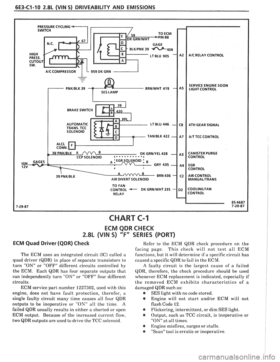
ECM QDR CHECK
2.8% (VIN S) 'TI' SERIES (PORT)
ECM Quad Driwer (QDR) Check
The ECM uses an integrated circuit (IC) called a
quad driver
(QDR) in place of separate transistors to
turn "ON" or "OFF" different circuits controlled by
the ECM. Each
QDR has four separate outputs that
can independently turn "ON" or "OFF" four different
circuits.
ECM service part number 1227302, used with this
engine, does not have fault protection, therefor,
a
single faulty circuit many time causes all four QDR
outputs to be inoperative or "OX" all the time.
A
failed QDR usually results in either a shorted or open
ECM output. Because of the increased current
flow,
two QDR outputs are used to drive the TCC solenoid. Refer
to the ECM QDR check procedure on the
facing page. This
check will not test all ECM
functions, but it will determine if a specific circuit has
caused a specific
QDR to fail in the ECM.
A faulty circuit is the largest cause of a failed
QDR, therefore, the check procedure should be used
whenever ECM replacement is indicated, especially if
the removed ECM exhibits characteristics of a
damaged QDR such as:
@ SES light with no code stored.
@ Engine will not start and/or ECM will not
flash Code 12.
@ Flickering, intermittent, or dim SES light.
@ Output, such as TCC circuit, is inoperative or
"ON" at all times.
@ ISngine misfires, surges or stalls.
@ "Scan" tool is erratic or inoperative.
Page 750 of 1825
DRIVEABILITY AND EMISSIONS 2.8L (VIN S) 6E3-CZ-15
NOTICE: Before instal ling new idle air control valve
assembly, the position of its pintle
MUST
be checked. If pintle is extended too far,
damage to the assembly may occur.
Measure
@ Distance from gasket mounting surface of IAC
valve assembly
(70) to tip of pintle, Dimension
"A" in Figure
C2-19.
Adjust
If distance is greater that 28 mm (1 118 in.), reduce -
it as follows:
a. If
IAC valve assembly has
a "collar" around
electrical connector end, use firm hand pressure
on pintle to retract it. (A slight side-to-side motion
may help.)
b. If IAC valve assembly has "no collar", compress
pintle-retaining spring toward body of the IAC
and try to turn pintle clockwise.
@ If pintle will turn, continue turning until
28mm
(1 118 in.) is reached. Return spring to
original position, with straight part of spring
end lined up with flat surface under the pintle
head.
@ If pintle will not turn, use firm hand pressure
to retract it.
Install or Connect
1. New IAC valve assembly gasket (71) on IAC valve
assembly
(70).
2. IAC valve assembly in idle airlvacuum signal
housing assembly
(60).
Tighten
IAC valve assembly to 18N.m (13 ft. Ibs.), with
wrench on hex surface only.
3. Electrical connector at IAC valve assembly (70).
Important
No physical adjustment is made to the IAC
assembly after installation.
IAC resetting occurs
after reinstallation on the vehicle, and is reset
after the engine is started and then the ignition
turned off.
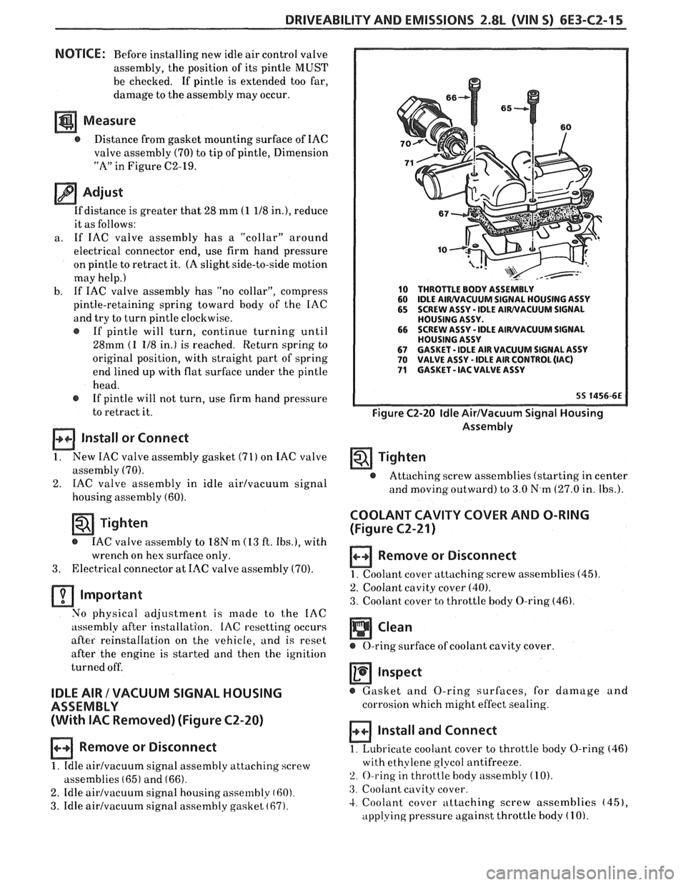
IDLE AIR / VACUUM SIGNAL HOUSING
ASSEMBLY
(With
IAC Removed) (Figure C2-20)
Remove or Disconnect
1. Idle airlvacuurn signal assembly attaching screw
assemblies
(65) and (66).
2. Idle airlvacuum signal housing assembly (60).
3. Idle airlvacuum signal assembly gasket (67).
10 THROTTLE BODY ASSEMBLY
60 IDLE AIWVACUUM SIGNAL
HOUSING ASSY
65 SCREW ASSY - IDLE AIWVACUUM SIGNAL
HOUSING ASSY.
66 SCREW
ASSY
- IDLE AIWVACUUM SIGNAL
HOUSING ASSY
67 GASKET - IDLE AIR VACUUM SIGNAL ASSY 70 VALVE ASSY - IDLE AIR CONTROL (IAC) 71 GASKET - IAC VALVE ASSY
Figure C2-20 Idle AirIVacuum Signal Housing
Assembly
Tighten
@ Attaching screw assemblies (starting in center
and
moving outward) to 3.0 N.m (27.0 in. Ibs.).
COOLANT CAVITY COVER AND O-RING
(Figure
C2-21)
Remove or Disconnect
1. Coolant cover attaching. screw assemblies (45).
2. Coolant cavity cover (40).
3. Coolant cover to throttle body O-ring (46).
Inspect
@ Gasket and O-ring surfaces, for damage and
corrosion which might effect sealing.
Install and Connect
1. Lubricate coolant cover to throttle body O-ring (46)
with ethylene glycol antifreeze.
2. O-ring in throttle body assembly (10).
:3. Coolant cavity cover.
4. Coolant cover attaching screw assemblies (451,
applying pressure against throttle body (1 0).
Page 755 of 1825
6E3-C2-20 2.8L (VIN S) DRIVEABILITY AND EMISSIONS
AIR THROTTLE FLOW BODY
LD START VALVE
8-5 BLUNVHT
BLUIBLK
GRMNVHT
. GRNIBLK
ECM
.
IAC COIL
"A" HI
IAC COIL "A" LO
IAC COIL "B" HI
C3 IAC COIL "B" LO
7-1 6-87
55 1800-6E
CHART C-2C
IDLE AIR CONTROL
2.8L (VIN S) ""F-SERIES (PORT)
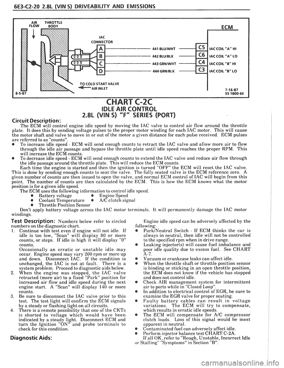
Circuit Description:
The ECM will control engine idle speed by moving the IAC valve to control air flow around the throttle
plate. It does this by sending voltage pulses to the proper motor winding for each IAC motor. This will cause
the motor shaft and valve to move in or out of the motor a given distance for each pulse received. ECM pulses
are referred to as "counts".
@ To increase idle speed - ECM will send enough counts to retract the IAC valve and allow more air to flow
through the idle air passage and bypass the throttle plate until idle speed reaches the proper RPM. This
will increase the ECM counts.
@ To decrease idle speed - ECM will send enough counts to extend the IAC valve and reduce air flow through
the idle passage around the throttle plate. This will reduce the ECM counts.
Each time the engine is started and then the ignition is turned "OFF" the ECM will reset the IAC valve.
This is done by sending enough counts to seat the valve. The fully seated valve is the ECM reference zero. A
given number of counts are then issued to open the valve, and normal ECM control of IAC will begin from this
point. The
number of counts are then calculated by the ECM. This is how the ECM knows what the motor
position is for
a given idle speed.
The ECM uses the following information to control idle speed.
@ Battery voltage @ Engine Speed
@ Coolant Temperature @ A/C clutch signal
@ Throttle Position Sensor
Don't apply battery voltage across the IAC motor terminals. It will permanently damage the IAC motor
windings.
Test Description: Numbers below refer to circled Engine
idle speed can be adversely affected by the
numbers on the diagnostic chart. following:
1. Continue
with test even if engine will not idle. If @ ParUNeutral Switch - If ECM thinks the car is
idle is too low, "Scan" will display
80 or more always
in neutral, then idle will not be controlled
counts, or steps. If idle is high it will display
"0" to the specified rpm when in drive range.
counts.
@ Leaking injector(s) will cause fuel imbalance and
Occasionally an erratic or unstable idle may poor
idle quality due to excess fuel. See CHART
occur. Engine speed may vary
200 rpm or more up A-7.
and down. Disconnect
EAC. If the condition is @ Vacuum or crankcase leaks can affect idle.
unchanged, the IAC is not at fault. There is
a @ When the throttle shaft or throttle position sensor
system problem. Proceed to diagnostic aids below. is
binding or sticking in an open throttle position,
2. When the engine was stopped, the IAC valve the
ECM does not know if the vehicle has stopped
retracted (more air) to a fixed "Park" position for and does not control idle.
increased air flow and idle speed during the next
@ Check AIR management system for intermittent
engine start. A "Scan" will display
140 or more air
to ports while in "Closed Loop".
counts. @ In addition to electrical control of EGR, be sure to
3. Be sure to disconnect the IAC valve prior to this examine the
EGR valve for proper seating.
test. The test light will confirm the ECM signals @ Faulty battery cables can result in voltage
by a steady or flashing light on all circuits. variations. The
ECM will try to compensate,
4. There is a remote possibility that one of the CKTs which results in erratic idle speeds.
is shorted to voltage which would have been @ The ECM will compensate for A/C compressor
indicated by a steady light. Disconnect ECM and clutch
loads. Loss of this signal would be most
turn the Ignition "ON" and probe terminals to apparent
in neutral.
check for this condition.
@ Contaminated fuel can adversely affect idle. @ Perform in
or Stalling" "Svmptoms" in Section "B".
Page 762 of 1825
DRIVEABILITY AND EMISSIONS f.8L (VIN 5) 6E3-C3-5
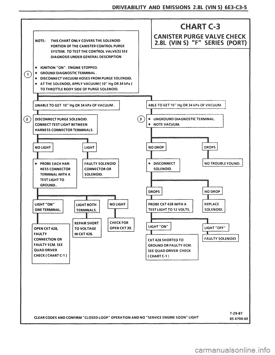
NOTE: THIS CHART ONLY COVERS THE SOLENOID
PORTION OF THE CANISTER CONTROL PURGE
SYSTEM. TO TEST THE CONTROL
VALVE(S) SEE
DIAGNOSIS UNDER GENERAL DESCRIPTION
@ IGNITION "ON". ENGINE STOPPED.
@ GROUND DIAGNOSTIC TERMINAL.
AT THE SOLENOID, APPLY VACUUM
( 10" Hg OR 34 kPa )
STIC TERMINAL.
TERMINAL
WITH A
TEST LIGHT TO
CONNECTION OR
FAULTY ECM. SEE
GROUND OR FAULTY ECM.
SEE QUAD DRIVER CHECK
Page 772 of 1825
DRIVEABILITY AND EMISSIONS 2.8L (WIN 5) 6E3-C6-3
4. If a leak is suspected on the pressure side of the
system or if
a hose or pipe has been disconnected
on the pressure side, the connections should be
checked for leaks with a soapy water solution.
With the pump running, bubbles will form if
a
leak exists.
Deceleration Valve
1. Connect tachometer, start engine and allow idle to
stabilize.
2. With the engine running at specified idle speed,
remove the small deceleration valve signal hose
from the manifold vacuum source.
3. Reconnect the signal hose and listen for air flow
through the ventilation pipe and into the
deceleration valve. There should also be a
noticeable speed drop when the signal hose is
reconnected.
4. If the air flow does not continue for at least one
second or the engine speed does not drop
noticeably, check the deceleration valve hoses for
restrictions or leaks.
5. If no restrictions or leaks are found, replace the
deceleration valve.
Check Valve
Inspect
1. A check valve should be inspected whenever the
hose is disconnected form
a check valve or
whenever check valve failure is suspected.
(A
pump that had become inoperative and had shown
indications of having exhaust gases in the pump
would indicate check valve failure).
2. Blow through the check valve (toward the exhaust
manifold) then attempt to suck back through the
check valve. Flow should only be in one
direction(towax-d the exhaust manifold). Replace
valve which does not operate properly.
ON-CAR SERVICE
DRIVE BELT
Remove or Disconnect
1. Inspect drive belt for ware, cracks or deterioration
and replace if required. When installing new belt,
it must be seated and fully secured in grooves of
A/C compressor, AIR pump, generator, and
crankshaft pulleys.
A.I.R. PUMP
Remove or Disconnect
1. Hold pump pulley from turning by compressing
drive belt, then loosen pump pulley bolts.
2. Loosen bolt, holding pump to mounting brackets,
release tension on drive belts.
3. Move belts out of the way, then remove pump
hoses, vacuum and electrical connections, and
control valve.
4. Pulley, then pump.
5. If required, insert needle nose pliers and pull filter
fan from hub.
Install or Connect
1. Air pump assembly, and tighten mounting bolts.
2. I-loses, vacuum and electrical connections, and
control valve
3. New
filter
fan on pump hub.
4. Spacer and pump pulley against centrifugal filter
fan.
5. Pump pulley bolts and tighten equally to 13 N m
(10 lb.
ft.). This will compress the centrifugal
filter fan onto the pump hole. Do not drive filter
fan on with a hammer. A slight amount of
interference with the housing bore is normal.
After a new filter fan has been installed, it
ma?;
squeal upon initial operation or until 0.11, sealing
lip has worn in. This
may require a short period of
purnp operation at various engine speeds.
6. Pump drive belt and adjust.
a Lon 7. Check air injection system for proper oper t'
(see CHART C-6)
AIR CONTROL VALVE
Remove or Disconnect
1. Battery ground cable.
2. Adapter bolts (See Figure C6-3).
3. Air outlet hoses from valve.
4. Adapter.
5. Electrical connectors and vacuum hoses from
valve. ve.
6. Control
va 1
Install or Connect
1. Control valve.
2. Electrical connectors and vacuum hoses.
3. Adapter.
4. Air hoses to valve.
5. Adapter bolts to pump.
6 Batterv ground crtble.
7. Check system operation (see CHART C-6)
Page 786 of 1825
DRIVEABILITY AND EMlSSlONS 2.8L (VIN %I 6E3-C8-1
TRANSMISSION CONVERTER CLUTCH (KC) SYSTEM
AND MANUAL
TRANSMISSION SHIFT LIGHT
CONTENTS
GENERAL DESCRIPTION ................ C8-1 DIAGNOSIS ..........ee...ee....e.e. C8-1
PURPOSE ......................... C8-1 SHIFT LIGHT (MIT) DESCRIPTION ........ C8-1
OPERATION ....................... C8-1 DIAGNOSIS ....................... .. C8-1
ON-CAR SERVICE ...................*. C8-1
GENERAL DESCRIPTION
PURPOSE
The transmission converter clutch (TCC) svstem
uses a solenoid operated valve in the automatic
transmission to couple the engine flywheel to the
output shaft of the transmission thru the torque
converter. This reduces the slippage losses in the
converter, which increases fuel economy.
OPERATION
For the converter clutch to apply, two conditions
must be met:
o Internal transmission fluid pressure must be
correct. For information on internal transmission
operation, see Section
"7A". This section will cover
only the electrical operation of the TCC system.
@ The ECM grounds a switch internally to turn on a
solenoid in the transmission. This moves a check
ball, which will allow the converter clutch to
apply, if the hydraulic pressure is correct, as
described above.
The ECM controls the TCC apply solenoid by
looking at several sensors:
@ Speedo Buffer Sensor (also called vehicle speed
sensor
(VSS). Speed must be above a certain value
before the clutch can apply.
@ Coolant Temperature Sensor. Engine must be
warmed up before clutch can apply about
65OC
(149°F').
Throttle position sensor ('I'PS). After the
converter clutch applies, the
HCM uses the
information from the TPS to release thc clutch
when the car is accelerating or decelerating at a
certain rate.
@ 'I'he brake switch is also part of the 'I'CC circuit as
it will remove battery voltage to the 'KC solenoid
when the brake pedal is depressed.
@ Gear Select Switch. The 4th gear switch is used to
send a signal to the
ECM telling it when the
transmission is in 4th gear. The ECM uses this
information to vary the conditions under which
the clutch applies or releases.
IIowever, the
transmission does not have to be in fourth gear in
order for the ECM to turn the clutch on.
If the converter clutch is applied at all times. the
engine will stall immediately, just as in
u manual
transmission with the clutch applied.
If the converter clutch does not apply, fuel
ecomony
may be lower than expected. If the vehicle
speed sensor fails, the TCC will not apply. If the 4th
gear switch does not operate, the TCC may not apply
at the right time.
DIAGNOSIS
The diagnosis of the TCC system is covered in
CHART C-8
. If the ECM detects a problem in the
system,
a Code 24 should set. In this case see Code 24
CHART.
SHIFT LIGHT (MiT) DESCRIPTION
'The purpose of the shift light is to provide a
display which indicates the optimum fuel economy
point for up
shifling the manual transmission based
on engine speed
and load. 'I'he display is a lamp on the
instrument panel. Activation of the ECM driver turns
the lamp
on.
'I'he shift light circuit can he checlted using
CHAR?' C-8C.
ON-CAR SERVICE
@ See Section "8B" if the shift light bulb needs
replacement.
@ See Section "6E" to repair wiring problem.
@ See Section "6C" if ECM is to be replaced.
Page 787 of 1825
6E3-C8-2 2.8L (VIN S) DRIVEABILITY AND EMISSIONS
VEHICLE SPEED SIGNAL
SPEED INPUT
CONNECTOR
aTH GEAR SIGNAL
422 TAN/BLK
4TH GEAR SW.
TRANSMISSION
ALDL CONNECTOR
TCC APPLY SOLENOID
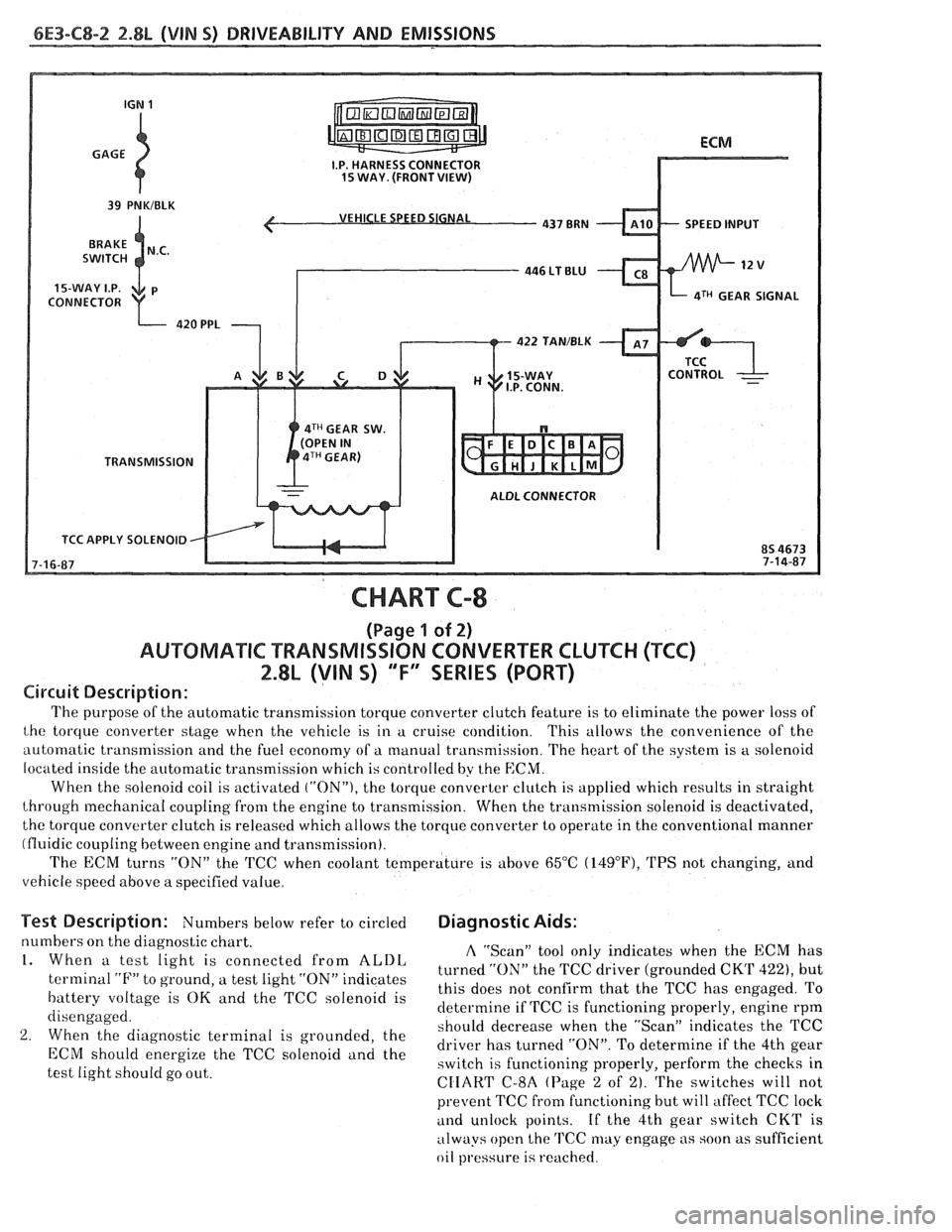
CHART C-8
(Page 1 of 2)
AUWBMATIC TRANSMISSION CONVERTER CLUTCH (TCC)
2.8L (VIN S) "F" SERIES (PORT)
Circuit Description:
The purpose of the automatic transmission torque converter clutch feature is to eliminate the power loss of
the torque converter stage when the vehicle is in a cruise condition. This allows the convenience of the
automatic transmission and the fuel economy of a manual transmission. The heart of the system is
a solenoid
located inside the automatic transmission which is controlled by the
ECM.
When the solenoid coil is activated ("ON"), the torque converter clutch is applied which results in straight
through mechanical coupling from the engine to transmission. When the transmission solenoid is deactivated,
the torque converter clutch is released which allows the torque converter to operate in the conventional manner
(fluidic coupling between engine and transmission).
The ECM turns
"ON" the 'KC when coolant temperature is above 65°C (14g°F), TPS not changing, and
vehicle speed above a specified value.
Test Description: Numbers below refer to circled Diagnostic Aids:
numbers on the diagnostic chart. A "Scan" tool only indicates when the ECM has 1. When a test light is connected from ALDL turned the TCC driver (grounded CKT 422), but terminal "F" to ground, a test light "ON" indicates
this does not confirm that the TCC has engaged. To battery voltage is OK and the TCC solenoid is
determine if TCC is functioning properly, engine rpm
disengaged.
should decrease when the "ScanJ' indicates the TCC
2. When the diagnostic terminal is grounded, the
driver has turned "ON". To determine if the 4th gear ECM energize the TCC "Ienoid and the switch is functioning properly, perform the checks in
test light should go out.
CIIART C-8A (Page 2 of 2). The switches will not
prevent TCC fi-om functioning but will affect TCC lock
and unlock points. If the 4th gear switch CKT is
always open the
TCC may engage as soon as sufficient
oil
pl.essure is reached.
Page 797 of 1825
CONNECTOR
TO ALTERNATOR
I.P.CONNECTOR
DK GRNNVHT 335
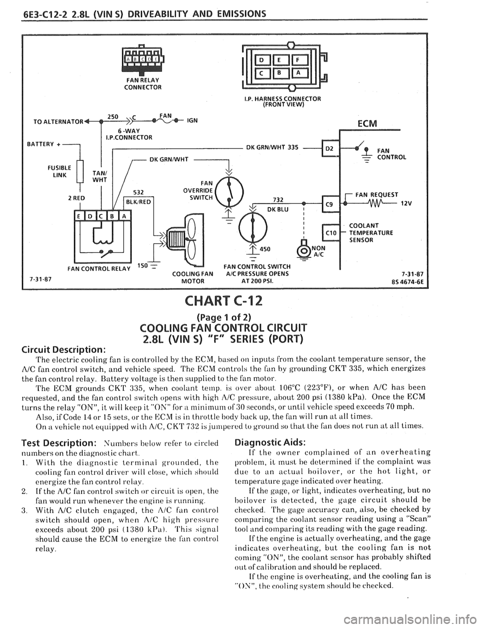
CHART C-12
(Page 1 of 2)
COOLING FAN CONTROL CIRCUIT
2.8L (VIN S) "F" SERIES (PORT)
Circuit Description:
'I'he electric cooling fan is controlled by the ECM, based on inputs from the coolant temperature sensor, the
NC fan control switch, and vehicle speed. 'I'he ECM controls the f~in by grounding CKT 335, which energizes
the fan control relay. Battery voltage is then supplied to the fan motor.
The ECM grounds
CKT 335, when coolant temp. is over about 106°C (223"F), or when AIC has been
requested, and the fan control switch opens with high
I\/C pressure, about 200 psi (1380 kPa). Once the ECM
turns the relay "ON", it will keep it "ON" for a nlinirnum of GO seconds, or until vehicle speed exceeds 70 mph.
Also, if Code
14 or 15 sets, or the ECM is in throttle body back up, the fan will run at all times.
On
kt vehicle not equipped with A/C, CK'I' 732 is,ju~rlperetl to ground so that Lhe fan does not run at all times.
Test Description: Numbers below refer to circled
numbers on the diagnostic chart,.
1. With the diagnostic terminal grounded, the
cooling
fan control driver will close, which should
energize the fan control
relay.
2. If the A/C fan control switch or circuit is open, the
fan would run whenever the engine is running.
3. With AIC clutch engaged, the i\lC fan control
switch should open, when
A/C high pressure
exceeds about
200 psi ( 1380 k13a). This signal
should cause the
ECM to energize the ran control
relay.
Diagnostic Aids:
If the owner complained of an overheating
problem, it
rnust he determined if the complaint was
clue to an actuill hoilover, or the hot light, or
temperature gage indicated over heating.
If the gage, or light, indicates overheating, but no
hoilover is detected, the gage circuit should he
checked.
'I'he gage accuracy can, also, be checked by
comparing the coolant sensor reading using a "Scan"
tool and comparing its reading with the gage reading.
If the engine is actually overheating, and the gage
indicates overheating, but the cooling fan is not
coming "ON", the coolant sensor has probably shifted
out
ofcalibration and should be replaced.
If
the engine is overheating, and the cooling fan is
"ON", the cooling system should hc checked.