1988 OPEL CALIBRA clock
[x] Cancel search: clockPage 215 of 525

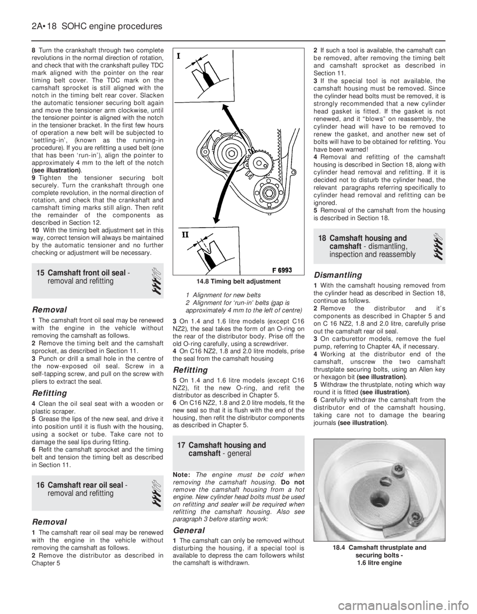
8Turn the crankshaft through two complete
revolutions in the normal direction of rotation,
and check that with the crankshaft pulley TDC
mark aligned with the pointer on the rear
timing belt cover. The TDC mark on the
camshaft sprocket is still aligned with the
notch in the timing belt rear cover. Slacken
the automatic tensioner securing bolt again
and move the tensioner arm clockwise, until
the tensioner pointer is aligned with the notch
in the tensioner bracket. In the first few hours
of operation a new belt will be subjected to
‘settling-in’, (known as the running-in
procedure). If you are refitting a used belt (one
that has been ‘run-in’), align the pointer to
approximately 4 mm to the left of the notch
(see illustration).
9Tighten the tensioner securing bolt
securely. Turn the crankshaft through one
complete revolution, in the normal direction of
rotation, and check that the crankshaft and
camshaft timing marks still align. Then refit
the remainder of the components as
described in Section 12.
10With the timing belt adjustment set in this
way, correct tension will always be maintained
by the automatic tensioner and no further
checking or adjustment will be necessary.
15Camshaft front oil seal -
removal and refitting
3
Removal
1The camshaft front oil seal may be renewed
with the engine in the vehicle without
removing the camshaft as follows.
2Remove the timing belt and the camshaft
sprocket, as described in Section 11.
3Punch or drill a small hole in the centre of
the now-exposed oil seal. Screw in a
self-tapping screw, and pull on the screw with
pliers to extract the seal.
Refitting
4Clean the oil seal seat with a wooden or
plastic scraper.
5Grease the lips of the new seal, and drive it
into position until it is flush with the housing,
using a socket or tube. Take care not to
damage the seal lips during fitting.
6Refit the camshaft sprocket and the timing
belt and tension the timing belt as described
in Section 11.
16Camshaft rear oil seal -
removal and refitting
3
Removal
1The camshaft rear oil seal may be renewed
with the engine in the vehicle without
removing the camshaft as follows.
2Remove the distributor as described in
Chapter 53On 1.4 and 1.6 litre models (except C16
NZ2), the seal takes the form of an O-ring on
the rear of the distributor body. Prise off the
old O-ring carefully, using a screwdriver.
4On C16 NZ2, 1.8 and 2.0 litre models, prise
the seal from the camshaft housing
Refitting
5 On 1.4 and 1.6 litre models (except C16
NZ2), fit the new O-ring, and refit the
distributor as described in Chapter 5.
6On C16 NZ2, 1.8 and 2.0 litre models, fit the
new seal so that it is flush with the end of the
housing, then refit the distributor components
as described in Chapter 5.
17Camshaft housing and
camshaft -general
Note: The engine must be cold when
removing the camshaft housing. Do not
remove the camshaft housing from a hot
engine. New cylinder head bolts must be used
on refitting and sealer will be required when
refitting the camshaft housing. Also see
paragraph 3 before starting work:
General
1The camshaft can only be removed without
disturbing the housing, if a special tool is
available to depress the cam followers whilst
the camshaft is withdrawn.2If such a tool is available, the camshaft can
be removed, after removing the timing belt
and camshaft sprocket as described in
Section 11.
3If the special tool is not available, the
camshaft housing must be removed. Since
the cylinder head bolts must be removed, it is
strongly recommended that a new cylinder
head gasket is fitted. If the gasket is not
renewed, and it “blows” on reassembly, the
cylinder head will have to be removed to
renew the gasket, and another new set of
bolts will have to be obtained for refitting. You
have been warned!
4Removal and refitting of the camshaft
housing is described in Section 18, along with
cylinder head removal and refitting. If it is
decided not to disturb the cylinder head, the
relevant paragraphs referring specifically to
cylinder head removal and refitting can be
ignored.
5Removal of the camshaft from the housing
is described in Section 18.
18Camshaft housing and
camshaft - dismantling,
inspection and reassembly
4
Dismantling
1With the camshaft housing removed from
the cylinder head as described in Section 18,
continue as follows.
2Remove the distributor and it’s
components as described in Chapter 5 and
on C 16 NZ2, 1.8 and 2.0 litre, carefully prise
out the camshaft rear oil seal.
3On carburettor models, remove the fuel
pump, referring to Chapter 4A, if necessary.
4Working at the distributor end of the
camshaft, unscrew the two camshaft
thrustplate securing bolts, using an Allen key
or hexagon bit (see illustration).
5Withdraw the thrustplate, noting which way
round it is fitted (see illustration).
6Carefully withdraw the camshaft from the
distributor end of the camshaft housing,
taking care not to damage the bearing
journals (see illustration).
2A•18SOHC engine procedures
14.8 Timing belt adjustment
1 Alignment for new belts
2 Alignment for ‘run-in’ belts (gap is
approximately 4 mm to the left of centre)
18.4 Camshaft thrustplate and
securing bolts -
1.6 litre engine
Page 237 of 525

4Position a container beneath the tank, then
disconnect the bottom hose and allow the
contents of the tank to drain into the
container. Suspend the bottom hose as high
as possible above the engine to prevent
coolant loss.
Refitting
5Refitting is a reversal of removal, but on
completion check and if necessary top-up the
coolant level, as described in Section 4. The
coolant drained from the expansion tank
during removal can be re-used, provided it
has not been contaminated.
Coolant level sensor
6The coolant level sensor, where fitted, is an
integral part of the expansion tank cap. If the
level sensor is faulty, the complete cap
assembly must be renewed.
14Temperature gauge sender -
removal and refitting
2
Removal
1The sender is screwed into the inlet
manifold on 1.4 and 1.6 litre models (except
C16 NZ2), and into the thermostat housing
on C16 NZ2, 1.8 and 2.0 litre models (see
illustrations).
2Partially drain the cooling system, as
described in Section 2, to minimise coolant
spillage.
3Disconnect the battery negative lead.4Disconnect the wiring from the switch, then
unscrew the switch from its location.
Refitting
5Refitting is a reversal of removal,
remembering the following points.
6Coat the sender threads with sealant before
fitting.
7Top-up the cooling system, as described in
Section 4.
8On completion, start the engine and check
the operation of the temperature gauge. Also
check for coolant leaks.
15Cooling fan switch -removal
and refitting
3
Note: A new sealing ring should be used
when refitting the switch
Removal
1The cooling fan switch is located at the
bottom right-hand corner of the radiator (see
illustration).
2If a faulty switch is suspected, the circuit to
the fan motor can be tested by temporarily
bridging the terminals in the switch wiring
plug, and switching on the ignition. If the
cooling fan now operates, the switch is faulty
and should be renewed. To remove the
switch, continue as follows.
3Disconnect the battery negative lead, then
disconnect the switch wiring plug if not
already done.4Drain the cooling system, as described in
Section 2.
5Unscrew the switch from the radiator and
recover the sealing ring.
Refitting
6Refitting is a reversal of removal, but use a
new sealing ring, and refill the cooling system
as described in Section 4.
7On completion, start the engine and run it
until it reaches normal operating temperature,
then continue to run the engine and check
that the cooling fan cuts in and functions
correctly.
16Heater control panel -
removal and refitting
3
Removal
1Disconnect the battery negative lead.
2Remove the passenger side footwell trim,
the steering column shrouds, and the
instrument panel lower and upper trim panels,
as described in Chapter 11.
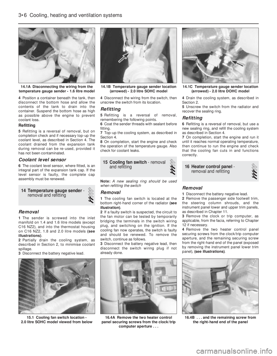
3Remove the clock or trip computer, as
applicable, from the facia, referring to Chapter
12 if necessary.
4Remove the two heater control panel
securing screws from the clock/trip computer
aperture, and the remaining securing screw
from the right-hand end of the panel (exposed
by removing the instrument panel lower trim
panel), (see illustrations).
3•6Cooling, heating and ventilation systems
14.1A Disconnecting the wiring from the
temperature gauge sender - 1.6 litre model14.1C Temperature gauge sender location
(arrowed) - 2.0 litre DOHC model
16.4B . . . and the remaining screw from
the right-hand end of the panel16.4A Remove the two heater control
panel securing screws from the clock/trip
computer aperture . . .15.1 Cooling fan switch location -
2.0 litre SOHC model viewed from below
14.1B Temperature gauge sender location
(arrowed) - 2.0 litre SOHC model
Page 249 of 525

REF•10MOTTest Checks
Exhaust system
MStart the engine. With your assistant
holding a rag over the tailpipe, check the
entire system for leaks. Repair or renew
leaking sections.
Jack up the front and rear of the vehicle,
and securely support it on axle stands.
Position the stands clear of the suspension
assemblies. Ensure that the wheels are
clear of the ground and that the steering
can be turned from lock to lock.
Steering mechanism
MHave your assistant turn the steering from
lock to lock. Check that the steering turns
smoothly, and that no part of the steering
mechanism, including a wheel or tyre, fouls
any brake hose or pipe or any part of the body
structure.
MExamine the steering rack rubber gaiters
for damage or insecurity of the retaining clips.
If power steering is fitted, check for signs of
damage or leakage of the fluid hoses, pipes or
connections. Also check for excessive
stiffness or binding of the steering, a missing
split pin or locking device, or severe corrosion
of the body structure within 30 cm of any
steering component attachment point.
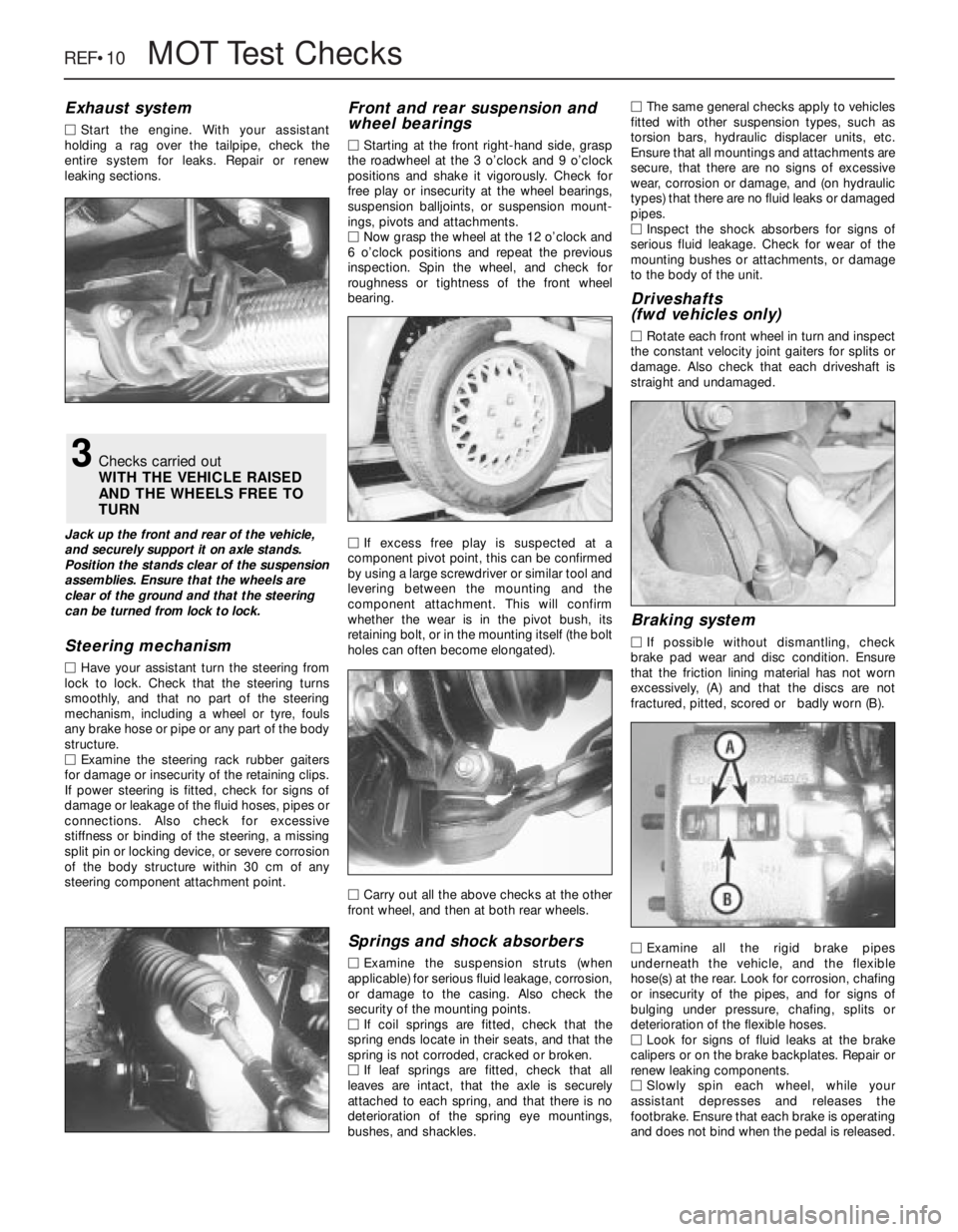
Front and rear suspension and
wheel bearings
MStarting at the front right-hand side, grasp
the roadwheel at the 3 o’clock and 9 o’clock
positions and shake it vigorously. Check for
free play or insecurity at the wheel bearings,
suspension balljoints, or suspension mount-
ings, pivots and attachments.
MNow grasp the wheel at the 12 o’clock and
6 o’clock positions and repeat the previous
inspection. Spin the wheel, and check for
roughness or tightness of the front wheel
bearing.
MIf excess free play is suspected at a
component pivot point, this can be confirmed
by using a large screwdriver or similar tool and
levering between the mounting and the
component attachment. This will confirm
whether the wear is in the pivot bush, its
retaining bolt, or in the mounting itself (the bolt
holes can often become elongated).
MCarry out all the above checks at the other
front wheel, and then at both rear wheels.
Springs and shock absorbers
MExamine the suspension struts (when
applicable) for serious fluid leakage, corrosion,
or damage to the casing. Also check the
security of the mounting points.
MIf coil springs are fitted, check that the
spring ends locate in their seats, and that the
spring is not corroded, cracked or broken.
MIf leaf springs are fitted, check that all
leaves are intact, that the axle is securely
attached to each spring, and that there is no
deterioration of the spring eye mountings,
bushes, and shackles.MThe same general checks apply to vehicles
fitted with other suspension types, such as
torsion bars, hydraulic displacer units, etc.
Ensure that all mountings and attachments are
secure, that there are no signs of excessive
wear, corrosion or damage, and (on hydraulic
types) that there are no fluid leaks or damaged
pipes.
MInspect the shock absorbers for signs of
serious fluid leakage. Check for wear of the
mounting bushes or attachments, or damage
to the body of the unit.
Driveshafts
(fwd vehicles only)
MRotate each front wheel in turn and inspect
the constant velocity joint gaiters for splits or
damage. Also check that each driveshaft is
straight and undamaged.
Braking system
MIf possible without dismantling, check
brake pad wear and disc condition. Ensure
that the friction lining material has not worn
excessively, (A) and that the discs are not
fractured, pitted, scored or badly worn (B).
MExamine all the rigid brake pipes
underneath the vehicle, and the flexible
hose(s) at the rear. Look for corrosion, chafing
or insecurity of the pipes, and for signs of
bulging under pressure, chafing, splits or
deterioration of the flexible hoses.
MLook for signs of fluid leaks at the brake
calipers or on the brake backplates. Repair or
renew leaking components.
MSlowly spin each wheel, while your
assistant depresses and releases the
footbrake. Ensure that each brake is operating
and does not bind when the pedal is released.
3Checks carried out
WITH THE VEHICLE RAISED
AND THE WHEELS FREE TO
TURN
Page 264 of 525

AABS components- 9•2, 9•16
Accelerator cable- 4A•5, 4B•9
Accelerator pedal- 4A•5
Acknowledgements- 0•4
Aerial- 12•17
Air cleaner- 1•3, 1•13, 4A•3, 4B•4
Air box- 4B•5
Air pump/cut off valve- 4C•2
Air temp control- 4B•5
Air vents- 3•8
Airbag- 12•19
Airflow meters- 4B•12
Alternator- 5•5
Alternator V-belt check- 1•12
Anti theft alarm- 12•19
Anti-roll bars- 10•8, 10•13, 10•17
Antifreeze mixture- 0•12, 0•17, 1•2, 3•3
ATF- 0•17, 1•2, 1•11, 7B•3
Automatic choke unit- 4A•9
Automatic transmission- 7B•1 et seq
cooler pipes and hoses - 7B•5
ECU - 7B•5
fault diagnosis - REF•12, REF•16
fluid - 0•17, 1•2, 1•11, 7B•3
kickdown switch - 7B•3
removal and refitting - 7B•6
selector control cable - 7B•4
speed sensors - 7B•6
starter inhibitor switch - 7B•3
temperature sensor - 7B•5
BBattery- 0•6, 0•15, 5•5
Bearings (engine)- 2A•31
Bleeding the brakes- 9•3
Bleeding the power steering- 10•22
Blower motor- 3•7
Body damage- 11•2
Body electrical systems - 12•1 et seq
Bodywork and fittings- 11•1 et seq
Bonnet- 11•4
Bonnet lock/release cable- 11•4
Boot lid- 11•4
Boot lid lock- 11•5
Bores- 2A•33
Brake checks- 1•12,
Braking system- 9•1 et seq
ABS components - 9•2, 9•16
backplate - 9•12
bleeding the brakes - 9•3
brake caliper - 9•8
brake disc - 9•10
brake drum - 9•11
brake fluid pipes and hoses - 9•18
brake lamp switch - 12•5
brake pads - 9•4
brake pedal - 9•21
brake shoes - 9•6
disc shield - 9•13
fault diagnosis - REF•12, REF•17
fluid - 0•13, 0•17handbrake adjustment - 9•18
handbrake cables - 9•19
handbrake lever - 9•20
master cylinder - 9•13
pressure valves - 9•18
vacuum servo unit - 9•15
wheel cylinder - 9•11
Bulbs- 12•2, 12•7, 12•11
Bumpers- 11•11
CCables:
bonnet release - 11•4
clutch - 6•2
handbrake - 9•19
selector automatic transmission - 7B•4
speedometer - 12•18
throttle - 4A•5, 4B•9
Caliper (brake)- 9•8
Camber- 10•1, 10•24
Camshaft- 2A•19, 2B•6
Camshaft housing- 2A•18
Camshaft oil seals- 2A•18
Capacities- 1•2
Carbon canister- 4C•4
Carburettor- 4A•5, 4A•11
Carpets- 11•2
Castor- 10•1, 10•24
Catalytic converter- 4C•3
Central door locking- 12•16
Centre console- 11•18
Cigarette lighter- 12•5
Clock- 12•6
Clutch- 6•1 et seq
cable - 6•2
fault diagnosis - REF•12, REF•15
pedal - 6•3
release bearing - 6•6
removal, inspection and refitting - 6•3
Coil- 5•9
Coil spring (rear)- 10•12, 10•15
Compression test- 2A•8
Computer components- 12•7
Connecting rods- 2A•29
Contents- 0•2
Control units- 4B•16, 7B•5
Conversion factors- REF•2
Coolant- 0•12, 0•17, 1•2, 3•3
Cooling, heating and ventilation systems-
3•1 et seq
blower motor - 3•7
coolant level sensor - 3•5
coolant pump - 3•4
cooling fan - 3•5
draining - 3•2
expansion tank - 3•5
fan switch - 3•6
fault diagnosis - REF•12, REF•15
filling - 3•2
flushing - 3•2
heater control panel - 3•6
heater matrix - 3•7
radiator - 3•3temperature gauge sender - 3•6
thermostat - 3•4
vents - 3•8
Courtesy lamp switch- 12•5
Crankcase ventilation system- 2A•7
Crankshaft- 2A•31
Crankshaft oil seals- 2A•26, 2B•6, 2B•9
Cylinder bores- 2A•33
Cylinder head- 2A•19, 2A•22, 2B•7DDents- 11•2
Depressurising fuel system- 4B•5
Differential bearing oil seal- 7A•3
Dimensions and weights- REF•1
Disc (brake)- 9•10
Distributor- 5•10
Door- 11•6
handle - 11•7
inner trim panel - 11•6
lock key battery - 1•13
mirror - 11•11
Driveshafts- 8•1 et seq
fault diagnosis - REF•12, REF•16
gaiter - 8•4
joint renewal - 8•4
Drum (brake)- 9•11
EEarth fault finding- 12•2
ECU’s - 4B•16, 7B•5
EGR components- 4C•2
Electric windows- 12•15
Electrical fault finding- 12•2
Electrical system (body)- 12•1 et seq
Electrical system- 0•14, 5•2
Electrical system fault diagnosis- REF•12,
REF•18
Electronic control units- 4B•16, 7B•5
Engine:
bearings - 2A•31
camshaft - 2A•19, 2B•6
camshaft housing - 2A•18
camshaft oil seals - 2A•18, 2B•6
codes - 2A•1, 2B•1
compartment - 0•10, 1•5
compression test - 2A•8
connecting rods - 2A•29
crankcase ventilation - 2A•7
crankshaft - 2A•31
crankshaft oil seals - 2A•26, 2B•6, 2B•9
cylinder bores - 2A•33
cylinder head - 2A•19, 2A•22, 2B•7
dismantling - 2A•12
DOHC - 2B•1 et seq
electrical systems - 5•1 et seq
fault diagnosis - REF•12, REF•13
flexplate (automatic transmission) - 2A•26
flywheel - 2A•26
main and big-end bearings - 2A•31
mountings (engine/transmission) - 2A•12,
2B•3
Index REF•25
REF
Note:References throughout this index are in the form - “Chapter number” • “page number”