1988 OPEL CALIBRA clock
[x] Cancel search: clockPage 146 of 525
42Where applicable, screw the pressure-
proportioning valves into the base of the
cylinder.
43Refit the master cylinder, as described in
Section 15.
17Master cylinder (ABS) -
general
The master cylinder fitted to models with
ABS cannot be dismantled, and no attempt
should be made at overhaul.
If faulty, the complete unit must be
renewed, as described in Section 15.
18Vacuum servo - description
and testing
Description
1The vacuum servo is fitted between the
brake pedal and the master cylinder, and
provides assistance to the driver when the
pedal is depressed, reducing the effort required
to operate the brakes. The unit is operated by
vacuum from the inlet manifold. With the brake
pedal released, vacuum is channelled to both
sides of the internal diaphragm. However,
when the pedal is depressed, one side of the
diaphragm is opened to atmosphere, resulting
in assistance to the pedal effort. Should the
vacuum servo develop a fault, the hydraulic
system is not affected, but greater effort will be
required at the pedal.
Testing
2The operation of the servo can be checked
as follows.
3With the engine stopped, destroy the
vacuum in the servo by depressing the brake
pedal several times.
4Hold the brake pedal depressed and start
the engine. The pedal should sink slightly as
the engine is started.
5If the pedal does not sink, check the servo
vacuum hose for leaks.
6If no defects are found in the vacuum hose,
the fault must lie in the servo itself.7No overhaul of the servo is possible, and if
faulty, the complete unit must be renewed.
19Vacuum servo - removal and
refitting
4
Note: During the 1989 model year, some
vehicles were produced with the brake pedal
height incorrectly set, resulting in the brake
pedal resting approximately 15.0 mm (0.6 in)
above the clutch pedal instead of 4.0 mm
(0.16 in below). The correct pedal height can
be set by adjusting the vacuum servo
operating fork dimension, as described in
paragraphs 15 and 16
Removal
1Disconnect the battery negative lead.
2Working inside the vehicle, remove the
lower trim panel from the driver’s footwell.
3Disconnect the wiring plug from the brake
lamp switch, then twist the switch anti-
clockwise and remove it from its bracket.
4Pull the spring clip from the right-hand end
of the servo fork-to-pedal pivot pin.
5Using a pair of pliers, pull back the end of
the pedal return spring from the pedal, to
enable the servo fork-to-pedal pivot pin to be
removed. Withdraw the pivot pin.
6Remove the windscreen cowl panel, as
described in Chapter 11, then remove the
windscreen wiper motor and linkage as
described in Chapter 12.7Remove the coolant expansion tank as
described in Chapter 3.
8Pull the vacuum pipe from the brake servo.
9Unscrew the two securing nuts, and
carefully withdraw the brake master cylinder
from the studs on the servo. Move the master
cylinder forwards slightly, taking care not to
strain the brake pipes.
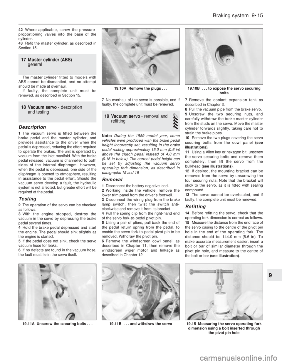
10Remove the two plugs covering the servo
securing bolts from the cowl panel (see
illustrations).
11Using a Allen key or hexagon bit, unscrew
the servo securing bolts and remove them
completely, then lift the servo from the
bulkhead (see illustrations).
12If desired, the mounting bracket can be
removed from the servo by unscrewing the
four securing nuts. Note that the bracket will
stick to the servo, as it is fitted with sealing
compound.
13The servo cannot be overhauled, and if
faulty, the complete unit must be renewed.
Refitting
14Before refitting the servo, check that the
operating fork dimension is correct as follows.
15Measure the distance from the end face of
the servo casing to the centre of the pivot pin
hole in the end of the operating fork. The
distance should be 144.0 mm (5.6 in). To
make accurate measurement easier, insert a
bolt or bar of similar diameter through the
pivot pin hole, and measure to the centre of
the bolt or bar (see illustration).
Braking system 9•15
19.11A Unscrew the securing bolts . . .19.15 Measuring the servo operating fork
dimension using a bolt inserted through
the pivot pin hole19.11B . . . and withdraw the servo
19.10B . . . to expose the servo securing
bolts19.10A Remove the plugs . . .
9
Page 152 of 525
19On DOHC models, use a new self-locking
nut to secure the equaliser yoke to the
handbrake lever operating rod, and screw the
nut onto the rod to the position noted before
removal.
20On SOHC models, tighten the cable
adjuster to expose the length of thread noted
before removal.
21Before lowering the vehicle to the ground,
adjust the handbrake, (Section 26).
29Brake pedal - removal and
refitting
3
Removal
1Disconnect the battery negative lead.
2Remove the lower trim panel from the
driver’s footwell.3Disconnect the wiring plug from the brake
lamp switch, then twist the switch anti-
clockwise and remove it from its bracket.
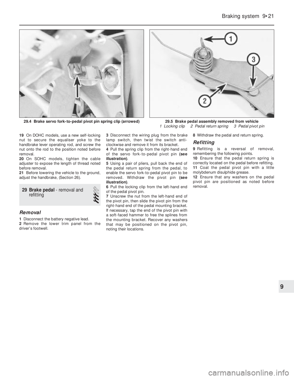
4Pull the spring clip from the right-hand end
of the servo fork-to-pedal pivot pin (see
illustration).
5Using a pair of pliers, pull back the end of
the pedal return spring from the pedal, to
enable the servo fork-to-pedal pivot pin to be
removed. Withdraw the pivot pin (see
illustration).
6Pull the locking clip from the left-hand end
of the pedal pivot pin.
7Unscrew the nut from the left-hand end of
the pivot pin, then slide the pivot pin from the
right-hand end of the pedal mounting bracket.
If necessary, tap the end of the pivot pin with
a soft-faced hammer to free the splines from
the mounting bracket. Recover any washers
that may be positioned on the pivot pin,
noting their locations.8Withdraw the pedal and return spring.
Refitting
9Refitting is a reversal of removal,
remembering the following points.
10Ensure that the pedal return spring is
correctly located on the pedal before refitting.
11Coat the pedal pivot pin with a little
molybdenum disulphide grease.
12Ensure that any washers on the pedal
pivot pin are positioned as noted before
removal.
Braking system 9•21
29.5 Brake pedal assembly removed from vehicle
1 Locking clip 2 Pedal return spring 3 Pedal pivot pin29.4 Brake servo fork-to-pedal pivot pin spring clip (arrowed)
9
Page 165 of 525
9Remove the two securing screws and
withdraw the sensor from the throttle body.
Refitting
10Refitting is a reversal of removal.
11On Motronic M4.1 system models, before
tightening the securing screws, adjust the
position of the sensor as follows:
a)Turn the sensor body anti-clockwise until
resistance is felt, then tighten the securing
screws.
b)When the throttle valve is opened, an
audible click should be noticeable from
the sensor, and similarly, this should be
repeated as the throttle valve is closed.
c)If necessary, adjust the position of the
sensor until a click is heard just as the
throttle valve begins to open.
12On M 1.5 systems, no adjustment is
required when refitting, as the sensor can only
be fitted in one position.
24Throttle valve potentiometer
- removal and refitting
3
Removal
1Disconnect the battery negative lead.
2Disconnect the wiring plugs at the inlet air
temperature sensor and at the hot film mass
airflow meter.
3Undo and remove the bolts securing the air
box to the throttle body. Remove the air box
complete with air trunking.4Disconnect the wiring plug at the throttle
valve potentiometer, then undo the two
screws and withdraw the potentiometer from
the throttle body.
Refitting
5Refitting is a reversal of removal.
25Airflow meter (if fitted) -
removal and refitting
3
Note: If the air funnel is removed, a new
gasket must be used on refitting. The airflow
meter securing bolts must be coated with
thread-locking compound on refitting
Removal
1Remove the air cleaner assembly, as
described in Section 4.
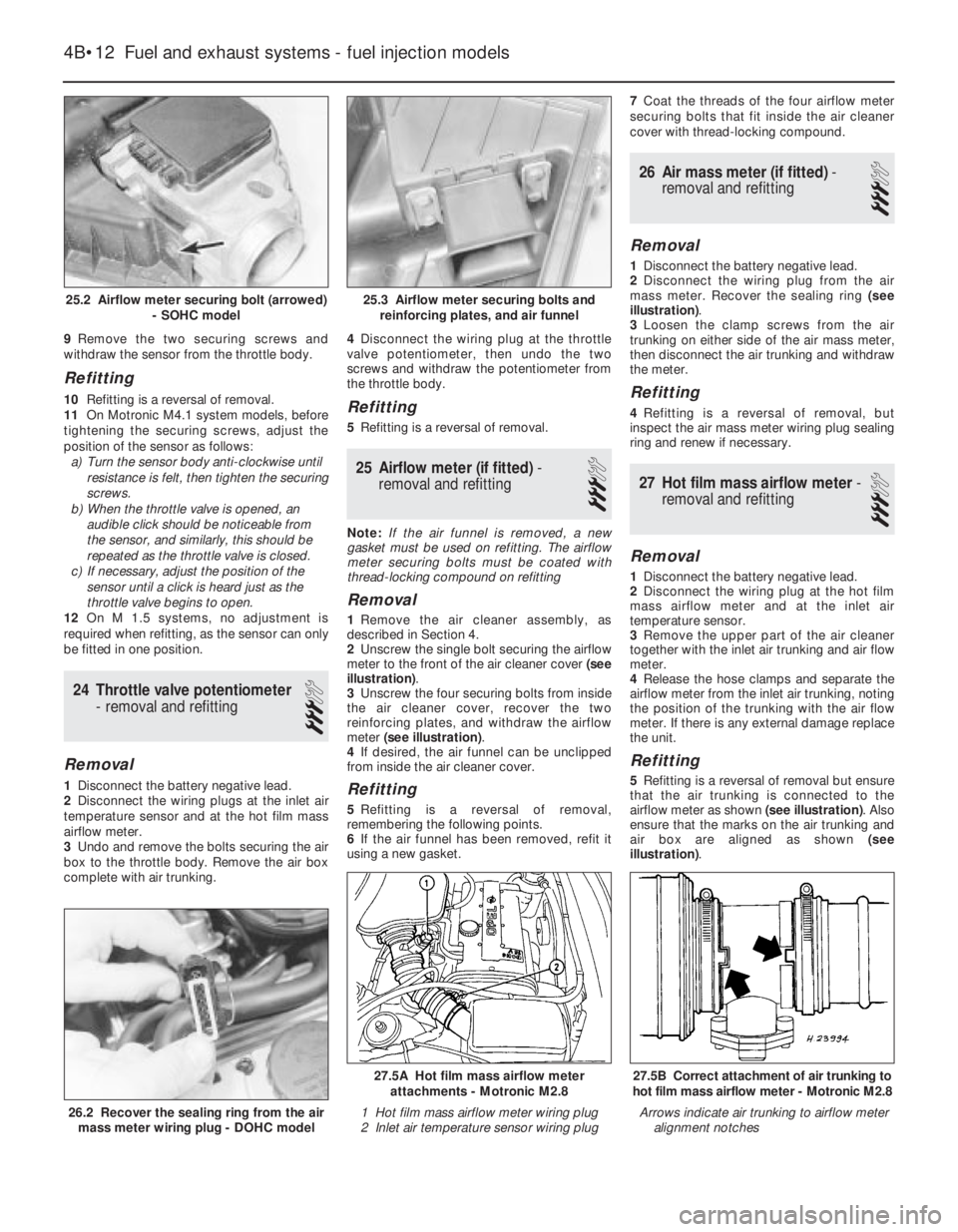
2Unscrew the single bolt securing the airflow
meter to the front of the air cleaner cover (see
illustration).
3Unscrew the four securing bolts from inside
the air cleaner cover, recover the two
reinforcing plates, and withdraw the airflow
meter (see illustration).
4If desired, the air funnel can be unclipped
from inside the air cleaner cover.
Refitting
5Refitting is a reversal of removal,
remembering the following points.
6If the air funnel has been removed, refit it
using a new gasket.7Coat the threads of the four airflow meter
securing bolts that fit inside the air cleaner
cover with thread-locking compound.
26Air mass meter (if fitted) -
removal and refitting
3
Removal
1Disconnect the battery negative lead.
2Disconnect the wiring plug from the air
mass meter. Recover the sealing ring (see
illustration).
3Loosen the clamp screws from the air
trunking on either side of the air mass meter,
then disconnect the air trunking and withdraw
the meter.
Refitting
4Refitting is a reversal of removal, but
inspect the air mass meter wiring plug sealing
ring and renew if necessary.
27Hot film mass airflow meter -
removal and refitting
3
Removal
1Disconnect the battery negative lead.
2Disconnect the wiring plug at the hot film
mass airflow meter and at the inlet air
temperature sensor.
3Remove the upper part of the air cleaner
together with the inlet air trunking and air flow
meter.
4Release the hose clamps and separate the
airflow meter from the inlet air trunking, noting
the position of the trunking with the air flow
meter. If there is any external damage replace
the unit.
Refitting
5Refitting is a reversal of removal but ensure
that the air trunking is connected to the
airflow meter as shown (see illustration). Also
ensure that the marks on the air trunking and
air box are aligned as shown (see
illustration).
4B•12Fuel and exhaust systems - fuel injection models
25.2 Airflow meter securing bolt (arrowed)
- SOHC model
26.2 Recover the sealing ring from the air
mass meter wiring plug - DOHC model
27.5B Correct attachment of air trunking to
hot film mass airflow meter - Motronic M2.8
Arrows indicate air trunking to airflow meter
alignment notches
27.5A Hot film mass airflow meter
attachments - Motronic M2.8
1 Hot film mass airflow meter wiring plug
2 Inlet air temperature sensor wiring plug
25.3 Airflow meter securing bolts and
reinforcing plates, and air funnel
Page 181 of 525
2Also check the security and condition of all
the engine related pipes and hoses. Ensure
that all cable-ties or securing clips are in
place, and in good condition. Clips that are
broken or missing can lead to chafing of the
hoses, pipes or wiring, which could cause
more serious problems in the future.
3Carefully check the radiator hoses and
heater hoses along their entire length. Renew
any hose that is cracked, swollen or
deteriorated. Cracks will show up better if the
hose is squeezed. Pay close attention to the
hose clips that secure the hoses to the
cooling system components. Hose clips can
pinch and puncture hoses, resulting in cooling
system leaks. It is always beneficial to renew
hose clips whenever possible.
4Inspect all the cooling system components
(hoses, joint faces, etc.) for leaks.
5Where any problems are found on system
components, renew the component or gasket
with reference to Chapter 3.
6Where applicable, inspect the automatic
transmission fluid cooler hoses for leaks or
deterioration.
7With the vehicle raised, inspect the petrol
tank and filler neck for punctures, cracks and
other damage. The connection between the
filler neck and tank is especially critical.
Sometimes a rubber filler neck or connecting
hose will leak due to loose retaining clamps or
deteriorated rubber.
8Carefully check all rubber hoses and metal
fuel lines leading away from the petrol tank.
Check for loose connections, deteriorated
hoses, crimped lines, and other damage. Pay
particular attention to the vent pipes and
hoses, which often loop up around the filler
neck and can become blocked or crimped.
Follow the lines to the front of the vehicle,
carefully inspecting them all the way. Renew
damaged sections as necessary.
9From within the engine compartment,
check the security of all fuel hose attachments
and pipe unions, and inspect the fuel hoses
and vacuum hoses for kinks, chafing and
deterioration.
10Where applicable, check the condition of
the power steering fluid hoses and pipes.5Steering and suspension
check
2
Front suspension and steering
check
1Raise the front of the car, and support on
axle stands (“Jacking and Vehicle Support”).
2Visually inspect the balljoint dust covers
and the steering rack-and-pinion gaiters for
splits, chafing or deterioration. Any wear of
these components will cause loss of lubricant,
together with dirt and water entry, resulting in
rapid wear of the balljoints or steering gear.
3On vehicles with power steering, check the
fluid hoses for chafing or deterioration, and
the pipe and hose unions for fluid leaks. Also
check for signs of fluid leakage under
pressure from the steering gear rubber
gaiters, which would indicate failed fluid seals
within the steering gear.
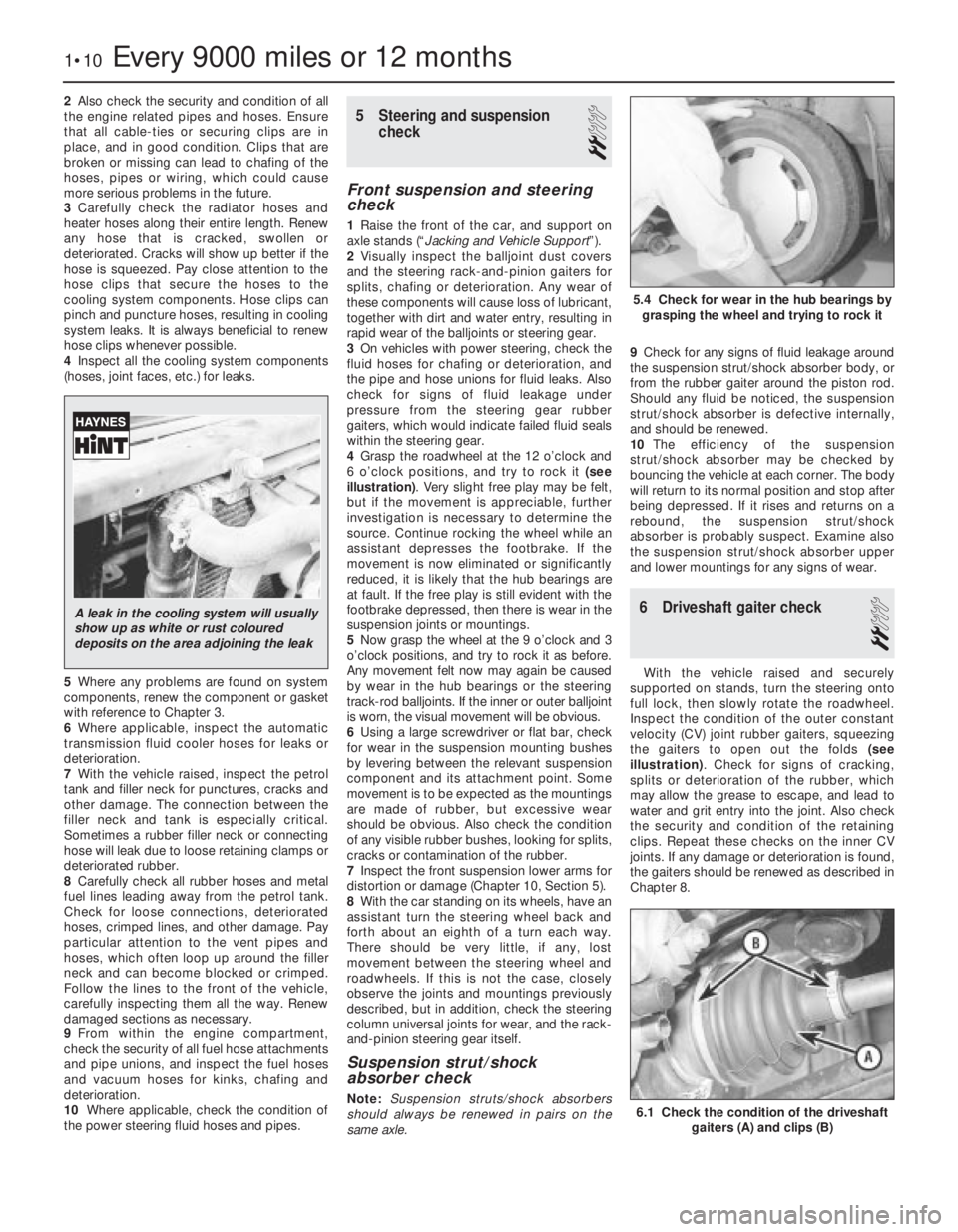
4Grasp the roadwheel at the 12 o’clock and
6 o’clock positions, and try to rock it (see
illustration). Very slight free play may be felt,
but if the movement is appreciable, further
investigation is necessary to determine the
source. Continue rocking the wheel while an
assistant depresses the footbrake. If the
movement is now eliminated or significantly
reduced, it is likely that the hub bearings are
at fault. If the free play is still evident with the
footbrake depressed, then there is wear in the
suspension joints or mountings.
5Now grasp the wheel at the 9 o’clock and 3
o’clock positions, and try to rock it as before.
Any movement felt now may again be caused
by wear in the hub bearings or the steering
track-rod balljoints. If the inner or outer balljoint
is worn, the visual movement will be obvious.
6Using a large screwdriver or flat bar, check
for wear in the suspension mounting bushes
by levering between the relevant suspension
component and its attachment point. Some
movement is to be expected as the mountings
are made of rubber, but excessive wear
should be obvious. Also check the condition
of any visible rubber bushes, looking for splits,
cracks or contamination of the rubber.
7Inspect the front suspension lower arms for
distortion or damage (Chapter 10, Section 5).
8With the car standing on its wheels, have an
assistant turn the steering wheel back and
forth about an eighth of a turn each way.
There should be very little, if any, lost
movement between the steering wheel and
roadwheels. If this is not the case, closely
observe the joints and mountings previously
described, but in addition, check the steering
column universal joints for wear, and the rack-
and-pinion steering gear itself.
Suspension strut/shock
absorber check
Note:Suspension struts/shock absorbers
should always be renewed in pairs on the
same axle.9Check for any signs of fluid leakage around
the suspension strut/shock absorber body, or
from the rubber gaiter around the piston rod.
Should any fluid be noticed, the suspension
strut/shock absorber is defective internally,
and should be renewed.
10The efficiency of the suspension
strut/shock absorber may be checked by
bouncing the vehicle at each corner. The body
will return to its normal position and stop after
being depressed. If it rises and returns on a
rebound, the suspension strut/shock
absorber is probably suspect. Examine also
the suspension strut/shock absorber upper
and lower mountings for any signs of wear.
6Driveshaft gaiter check
2
With the vehicle raised and securely
supported on stands, turn the steering onto
full lock, then slowly rotate the roadwheel.
Inspect the condition of the outer constant
velocity (CV) joint rubber gaiters, squeezing
the gaiters to open out the folds (see
illustration). Check for signs of cracking,
splits or deterioration of the rubber, which
may allow the grease to escape, and lead to
water and grit entry into the joint. Also check
the security and condition of the retaining
clips. Repeat these checks on the inner CV
joints. If any damage or deterioration is found,
the gaiters should be renewed as described in
Chapter 8.
1•10Every 9000 miles or 12 months
6.1 Check the condition of the driveshaft
gaiters (A) and clips (B)
5.4 Check for wear in the hub bearings by
grasping the wheel and trying to rock it
A leak in the cooling system will usually
show up as white or rust coloured
deposits on the area adjoining the leak
Page 192 of 525

Apply a little grease to the threads of the
securing bolt, and tighten it to the specified
torque in the two stages given in the Specifi-
cations. Ensure that the thrustwasher is in
place under the bolt head, and prevent the
crankshaft from turning as during removal.
23Refit the camshaft sprockets. Ensure that
the locating pins on the ends of the camshafts
engage with the holes in the sprockets and
with the sprocket timing marks facing
forwards. Then tighten the securing bolts to
the specified torque in the two stages given in
the Specifications. Prevent the camshafts
from turning as during removal.
24Check the condition of the camshaft
cover rubber gasket and renew if necessary,
then refit the camshaft cover and tighten the
securing bolts (see illustration).
25Refit the HT leads to the spark plugs
(ensuring that they are refitted to their correct
cylinders), then clip the leads to the end of the
camshaft cover. Refit the spark plug cover
and tighten the securing bolts.
26Reconnect the breather hose to the
camshaft cover.
27Temporarily refit the crankshaft pulley,
and ensure that the crankshaft pulley and
camshaft sprocket timing marks are still
aligned as described in paragraph 6. Then fit a
new timing belt around the sprockets and
pulleys, starting at the crankshaft sprocket.
28Refit the crankshaft pulley, and tighten the
securing bolts to the specified torque. If
necessary, prevent the crankshaft from
turning as during removal. 29Adjust the timing belt tension, as
described from paragraph 35 onwards.
30Refit the outer timing belt cover, ensuring
that the rubber grommets are in place in the
screw holes, and tighten the securing screws.
31Refit the alternator drivebelt and adjust
the drivebelt tension, as described in Chapter
5.
32Refit the power steering pump drivebelt
and adjust the drivebelt tension, as described
in Chapter 10.
33Refit the air cleaner components as
applicable, referring to Chapter 4B, if
necessary.
34Reconnect the battery negative lead.
Adjustment
Note: The manufacturers specify the use of
special adjustment wrench Vauxhall tool No
KM-666 for adjusting the timing belt tension. If
access to this tool cannot be obtained an
approximate adjustment can be achieved
using the method described in this Section.
However it is emphasised that the vehicle
should be taken to a dealer at the earliest
possible opportunity to have the tension
adjusted using the special tool. Do not drive
the vehicle over any long distance until the
belt tension has been adjusted by a dealer
Approximate adjustment
35No checking of timing belt adjustment is
specified, and the following adjustment
procedure applies to a newly fitted belt. The
adjustment must be carried out with the
engine cold.36With the timing belt cover removed and
the tensioner pulley bolt slackened, ensure
that the TDC marks on the camshaft
sprockets and the crankshaft pulley are
aligned as described in paragraph 6. If
necessary, turn the crankshaft to achieve
alignment.
37Have an assistant press the tensioner
pulley against the belt until the belt can just be
twisted through 45°, using moderate pressure
with the thumb and forefinger, on the longest
belt run between the exhaust camshaft
sprocket and the belt idler pulley.
38Have the assistant hold the tensioner
pulley in position, and tighten the tensioner
pulley bolt to the specified torque in the two
stages given in the Specifications.
39Turn the crankshaft clockwise through
two complete revolutions, and check that,
with the crankshaft pulley TDC mark aligned
with the pointer on the rear timing belt cover,
the TDC marks on the camshaft sprockets are
still aligned with the notches in the camshaft
cover.
40Proceed as described in paragraphs 30 to
34, inclusive.
41Have the belt tension adjusted by a
Vauxhall dealer using the manufacturer’s
special tool at the earliest opportunity.Adjustment using Vauxhall special
tool (KM-666)
42Proceed as described in paragraphs 35
and 36.
43Fit the special tool KM-666 to the belt
tensioner pulley mounting plate, in
accordance with the tool manufacturer’s
instructions.
44Working anti-clockwise from the TDC
mark on the exhaust camshaft sprocket, mark
the seventh tooth on the sprocket (see
illustration).
45Turn the crankshaft clockwise until this
tooth is aligned with the TDC notch in the
camshaft cover. The crankshaft must be
turned evenly and without jerking, to prevent
the timing belt from jumping off the sprockets
and pulleys.
46Tighten the tensioner pulley bolt to the
specified torque in the two stages given in the
Specifications.
47Remove the special tool.
DOHC engine procedures 2B•5
4.21 Belt tensioner pulley and spacer
sleeve. Note that smaller diameter of
spacer sleeve fits against pulley
4.44 Working anti-clockwise from the TDC
mark on the exhaust camshaft sprocket,
mark the seventh tooth on the sprocket4.24 Tightening a camshaft cover securing
bolt
4.19B Rear timing belt cover lower right-
hand securing bolt4.19A Timing belt outer cover screw upper
stud (1) and rear belt cover upper
securing bolts (2)
2B
Page 193 of 525
48Turn the crankshaft clockwise until the
TDC marks on the camshaft sprockets are
aligned with the notches in the camshaft
cover, and check that the crankshaft pulley
TDC mark is aligned with the pointer on the
rear timing belt cover.
49Proceed as described in paragraphs 30 to
34 inclusive.
5Timing belt, with automatic
adjuster- removal, refitting
and adjustment
3
Removal
1The operations are essentially the same as
described in Section 4, except that the
tensioner pulley incorporates an automatic
adjuster that simplifies the procedure as
follows.
2To release the belt tension before removal,
unscrew the timing belt tensioner pulley
securing bolt slightly then, with a large
screwdriver (or similar tool) inserted in the slot
on the tensioner arm, turn the tensioner arm
until the timing belt is slack. Tighten the
securing bolt slightly to hold the tensioner in
this position.
Refitting
3To refit the timing belt, first ensure that the
coolant pump is correctly positioned by
checking that the lug on the coolant pump
flange is aligned with the corresponding lug
on the cylinder block. If this is not the case,
slacken the coolant pump mounting bolts
slightly and move the pump accordingly.
Tighten the bolts to the specified torque on
completion (see Chapter 3).
4Refit the timing belt as described in Section 4,
then tension it as follows.
Adjustment
5Slacken the tensioner pulley securing bolt
and move the tensioner arm anti-clockwise,
until the tensioner pointer lies at its stop.
Tighten the tensioner pulley securing bolt to
hold the tensioner in this position.
6Turn the crankshaft through two complete
revolutions in the normal direction of rotation
and check that with the crankshaft pulley TDC
mark aligned with the pointer on the rear
timing belt cover, the TDC marks on the
camshaft sprockets are still aligned with the
notches in the camshaft cover.
7Slacken the tensioner pulley securing bolt
once again and move the tensioner arm
clockwise, until the tensioner pointer is
aligned with the notch in the tensioner. In the
first few hours of operation a new belt will be
subjected to ‘settling-in’, (known as the
running-in procedure). If you are refitting a
used belt (one that has been ‘run-in’), align the
pointer to approximately 4 mm to the left of
the notch, refer to Section 14 in Chapter 2A.
Tighten the tensioner pulley securing bolt
securely. Turn the crankshaft through onecomplete revolution in the normal direction of
rotation and check that the crankshaft and
camshaft timing marks still align, then refit the
remainder of the components as described in
Section 4.
8With the timing belt adjustment set in this
way, correct tension will always be maintained
by the automatic tensioner and no further
checking or adjustment will be necessary.
6Camshaft front oil seal-
removal and refitting
3
Note: A new timing belt should be used on
refitting
Removal
1The camshaft front oil seals may be
renewed with the engine in the vehicle without
removing the camshafts as follows.
2Remove the timing belt and the relevant
camshaft sprocket(s), as described in Section 4.
3Punch or drill a small hole in the centre of
the now-exposed oil seal. Screw in a
self-tapping screw, and pull on the screw with
pliers to extract the seal.
4Clean the oil seal seat with a wooden or
plastic scraper.
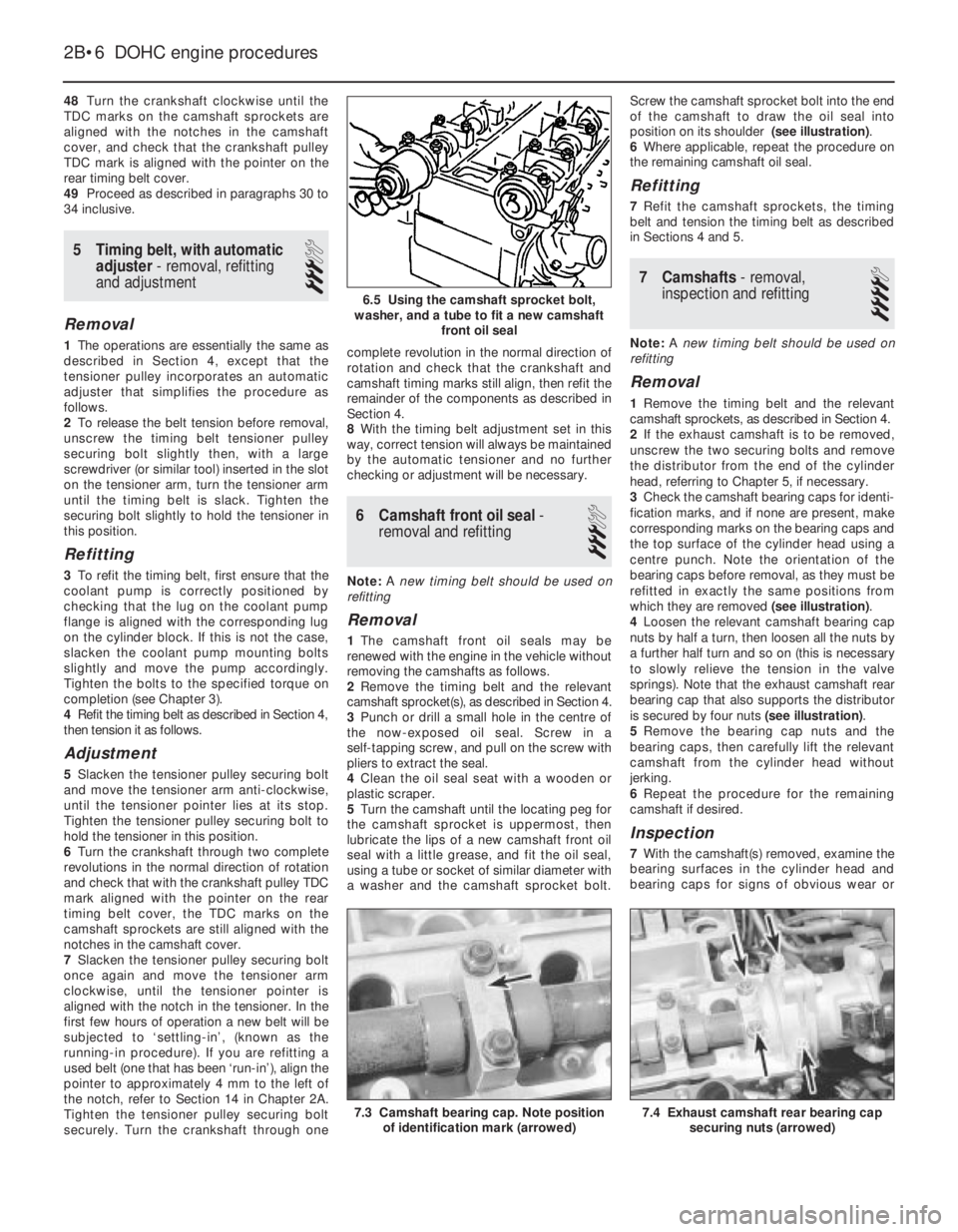
5Turn the camshaft until the locating peg for
the camshaft sprocket is uppermost, then
lubricate the lips of a new camshaft front oil
seal with a little grease, and fit the oil seal,
using a tube or socket of similar diameter with
a washer and the camshaft sprocket bolt.Screw the camshaft sprocket bolt into the end
of the camshaft to draw the oil seal into
position on its shoulder (see illustration).
6Where applicable, repeat the procedure on
the remaining camshaft oil seal.
Refitting
7Refit the camshaft sprockets, the timing
belt and tension the timing belt as described
in Sections 4 and 5.
7Camshafts- removal,
inspection and refitting
4
Note: A new timing belt should be used on
refitting
Removal
1Remove the timing belt and the relevant
camshaft sprockets, as described in Section 4.
2If the exhaust camshaft is to be removed,
unscrew the two securing bolts and remove
the distributor from the end of the cylinder
head, referring to Chapter 5, if necessary.
3Check the camshaft bearing caps for identi-
fication marks, and if none are present, make
corresponding marks on the bearing caps and
the top surface of the cylinder head using a
centre punch. Note the orientation of the
bearing caps before removal, as they must be
refitted in exactly the same positions from
which they are removed (see illustration).
4Loosen the relevant camshaft bearing cap
nuts by half a turn, then loosen all the nuts by
a further half turn and so on (this is necessary
to slowly relieve the tension in the valve
springs). Note that the exhaust camshaft rear
bearing cap that also supports the distributor
is secured by four nuts (see illustration).
5Remove the bearing cap nuts and the
bearing caps, then carefully lift the relevant
camshaft from the cylinder head without
jerking.
6Repeat the procedure for the remaining
camshaft if desired.
Inspection
7With the camshaft(s) removed, examine the
bearing surfaces in the cylinder head and
bearing caps for signs of obvious wear or
2B•6DOHC engine procedures
6.5 Using the camshaft sprocket bolt,
washer, and a tube to fit a new camshaft
front oil seal
7.4 Exhaust camshaft rear bearing cap
securing nuts (arrowed)7.3 Camshaft bearing cap. Note position
of identification mark (arrowed)
Page 213 of 525
32Release the securing clips and remove the
main outer timing belt cover, then unclip the
smaller outer timing belt cover from the
coolant pump.
33Turn the crankshaft through at least
quarter of a turn clockwise using a socket or
spanner on the crankshaft sprocket bolt.
34If the special gauge is available, place the
locked gauge at the centre of the belt run
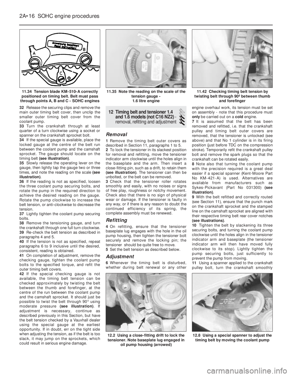
between the coolant pump and the camshaft
sprocket. The gauge should locate on the
timing belt (see illustration).
35Slowly release the operating lever on the
gauge, then lightly tap the gauge two or three
times, and note the reading on the scale (see
illustration).
36If the reading is not as specified, loosen
the three coolant pump securing bolts, and
rotate the pump in the required direction to
achieve the desired reading on the gauge.
Rotate the pump clockwise to increase the
belt tension, or anti-clockwise to decrease the
tension.
37Lightly tighten the coolant pump securing
bolts.
38Remove the tensioning gauge, and turn
the crankshaft through one full turn clockwise.
39Re-check the belt tension as described in
paragraphs 4 and 5.
40If the tension is not as specified, repeat
paragraphs 6 to 9 inclusive until the desired,
consistent, reading is obtained.
41On completion of adjustment, remove the
checking gauge, tighten the coolant pump
bolts to the specified torque, and refit the
outer timing belt covers.
42If the special checking gauge is not
available, the timing belt tension can be
checked approximately by twisting the belt
between the thumb and forefinger, at the
centre of the run between the coolant pump
and the camshaft sprocket. It should just be
possible to twist the belt through 90°using
moderate pressure (see illustration). If
adjustment is necessary, continue as
described previously in this Section, but have
the belt tension checked by a Vauxhall dealer
using the special gauge at the earliest
opportunity. If in doubt, err on the tight side
when adjusting the tension, as if the belt is too
slack, it may jump on the sprockets, which
could result in serious engine damage.12Timing belt and tensioner 1.4
and 1.6 models (not C16 NZ2) -
removal, refitting and adjustment
3
Removal
1Remove the timing belt outer covers as
described in Section 11, paragraphs 1 to 5.
2To lock the tensioner in its slackest position
for removal and refitting, move the tensioner
indicator arm clockwise until the holes align in
the baseplate and the arm. Then insert a
close-fitting pin, such as a drift, to retain them
(see illustration). The tensioner can then be
unbolted, or the belt can be removed.
3Check that the tensioner roller rotates
smoothly and easily, with no noises or signs
of free play, roughness or notchy movement.
Check also that there is no sign of physical
wear or damage. If the tensioner is faulty in
any way, or if there is any reason to doubt the
continued efficiency of its spring, the
complete assembly must be renewed.
Refitting
4On refitting, ensure that the tensioner
baseplate lug engages with the hole in the oil
pump housing, then tighten the tensioner bolt
securely and remove the locking pin; the
tensioner should be quite free to move.
5Set the belt tension as described below.
Adjustment
6Whenever the timing belt is disturbed,
whether during belt renewal or any otherengine overhaul work, its tension must be set
on assembly - note that this procedure must
only be carried out on a cold engine.
7It is assumed that the belt has been
removed and refitted, i.e. that the crankshaft
pulley and timing belt outer covers are
removed, that the tensioner is unlocked (see
above) and that No 1 cylinder is in its firing
position (just before TDC on the compression
stroke). Temporarily refit the crankshaft pulley
bolt and remove the spark plugs so that the
crankshaft can be rotated easily.
8Note also that turning the coolant pump
with the precision required is a great deal
easier if a special spanner (Kent-Moore Part
No KM-421-A) is used. Alternatives are
available from manufacturers such as
Sykes-Pickavant (Part No 031300) (see
illustration).
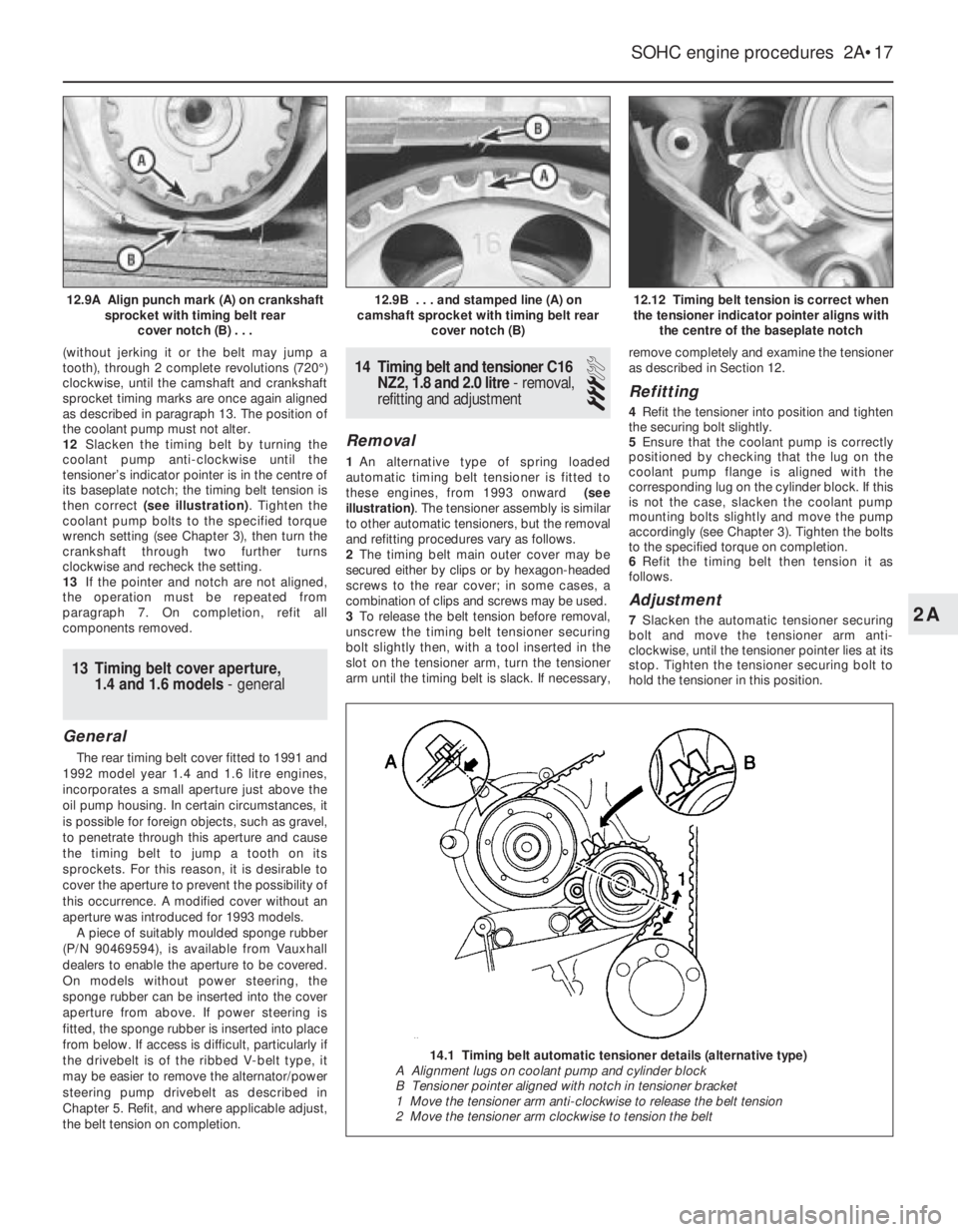
9With the belt refitted and correctly routed
(see Section 11), ensure that the punch mark
on the crankshaft sprocket and the stamped
line on the camshaft sprocket are aligned with
their respective timing belt rear cover notches
(see illustrations).
10Tighten the belt by slackening its three
securing bolts, and turning the coolant pump
clockwise until the holes align in the tensioner
indicator arm and baseplate (the tensioner
indicator arm will then have moved fully
clockwise to its stop). Lightly tighten the
pump securing bolts, just sufficiently to
prevent the pump from moving.
11Using a spanner applied to the crankshaft
pulley bolt, turn the crankshaft smoothly
2A•16SOHC engine procedures
11.34 Tension blade KM-510-A correctly
positioned on timing belt. Belt must pass
through points A, B and C - SOHC engines11.42 Checking timing belt tension by
twisting belt through 90º between thumb
and forefinger
12.8 Using a special spanner to adjust the
timing belt by moving the coolant pump12.2 Using a close-fitting drift to lock the
tensioner. Note baseplate lug engaged in
oil pump housing (arrowed)
11.35 Note the reading on the scale of the
tension gauge -
1.6 litre engine
Page 214 of 525
(without jerking it or the belt may jump a
tooth), through 2 complete revolutions (720°)
clockwise, until the camshaft and crankshaft
sprocket timing marks are once again aligned
as described in paragraph 13. The position of
the coolant pump must not alter.
12Slacken the timing belt by turning the
coolant pump anti-clockwise until the
tensioner’s indicator pointer is in the centre of
its baseplate notch; the timing belt tension is
then correct (see illustration). Tighten the
coolant pump bolts to the specified torque
wrench setting (see Chapter 3), then turn the
crankshaft through two further turns
clockwise and recheck the setting.
13If the pointer and notch are not aligned,
the operation must be repeated from
paragraph 7. On completion, refit all
components removed.
13Timing belt cover aperture,
1.4 and 1.6 models - general
General
The rear timing belt cover fitted to 1991 and
1992 model year 1.4 and 1.6 litre engines,
incorporates a small aperture just above the
oil pump housing. In certain circumstances, it
is possible for foreign objects, such as gravel,
to penetrate through this aperture and cause
the timing belt to jump a tooth on its
sprockets. For this reason, it is desirable to
cover the aperture to prevent the possibility of
this occurrence. A modified cover without an
aperture was introduced for 1993 models.
A piece of suitably moulded sponge rubber
(P/N 90469594), is available from Vauxhall
dealers to enable the aperture to be covered.
On models without power steering, the
sponge rubber can be inserted into the cover
aperture from above. If power steering is
fitted, the sponge rubber is inserted into place
from below. If access is difficult, particularly if
the drivebelt is of the ribbed V-belt type, it
may be easier to remove the alternator/power
steering pump drivebelt as described in
Chapter 5. Refit, and where applicable adjust,
the belt tension on completion.
14Timing belt and tensioner C16
NZ2, 1.8 and 2.0 litre - removal,
refitting and adjustment
3
Removal
1An alternative type of spring loaded
automatic timing belt tensioner is fitted to
these engines, from 1993 onward (see
illustration). The tensioner assembly is similar
to other automatic tensioners, but the removal
and refitting procedures vary as follows.
2The timing belt main outer cover may be
secured either by clips or by hexagon-headed
screws to the rear cover; in some cases, a
combination of clips and screws may be used.
3To release the belt tension before removal,
unscrew the timing belt tensioner securing
bolt slightly then, with a tool inserted in the
slot on the tensioner arm, turn the tensioner
arm until the timing belt is slack. If necessary,remove completely and examine the tensioner
as described in Section 12.
Refitting
4Refit the tensioner into position and tighten
the securing bolt slightly.
5Ensure that the coolant pump is correctly
positioned by checking that the lug on the
coolant pump flange is aligned with the
corresponding lug on the cylinder block. If this
is not the case, slacken the coolant pump
mounting bolts slightly and move the pump
accordingly (see Chapter 3). Tighten the bolts
to the specified torque on completion.
6Refit the timing belt then tension it as
follows.
Adjustment
7Slacken the automatic tensioner securing
bolt and move the tensioner arm anti-
clockwise, until the tensioner pointer lies at its
stop. Tighten the tensioner securing bolt to
hold the tensioner in this position.
SOHC engine procedures 2A•17
12.12 Timing belt tension is correct when
the tensioner indicator pointer aligns with
the centre of the baseplate notch12.9B . . . and stamped line (A) on
camshaft sprocket with timing belt rear
cover notch (B)12.9A Align punch mark (A) on crankshaft
sprocket with timing belt rear
cover notch (B) . . .
2A
14.1 Timing belt automatic tensioner details (alternative type)
A Alignment lugs on coolant pump and cylinder block
B Tensioner pointer aligned with notch in tensioner bracket
1 Move the tensioner arm anti-clockwise to release the belt tension
2 Move the tensioner arm clockwise to tension the belt