1988 OPEL CALIBRA air filter
[x] Cancel search: air filterPage 176 of 525
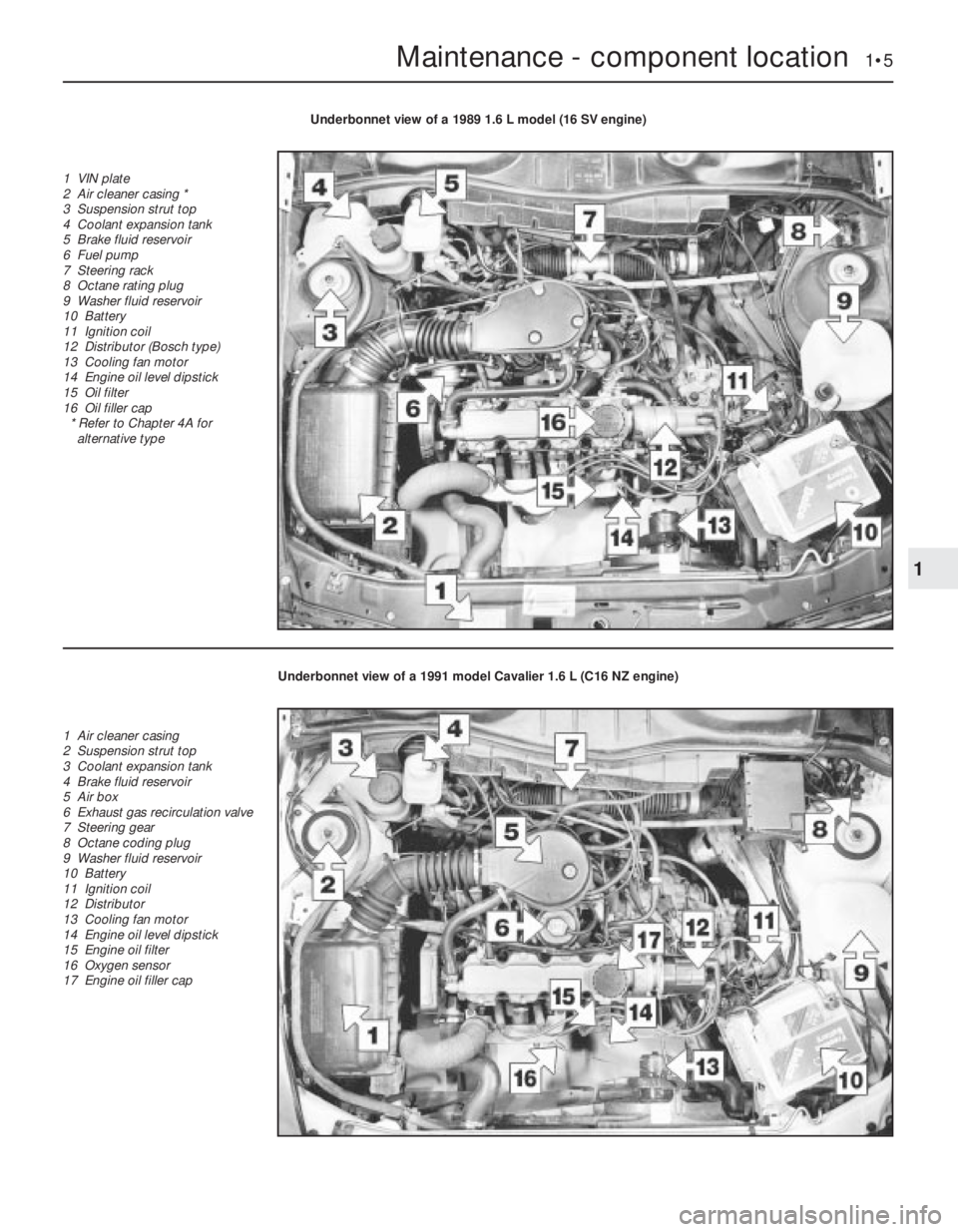
Maintenance - component location 1•5
1
Underbonnet view of a 1989 1.6 L model (16 SV engine)
1 VIN plate
2 Air cleaner casing *
3 Suspension strut top
4 Coolant expansion tank
5 Brake fluid reservoir
6 Fuel pump
7 Steering rack
8 Octane rating plug
9 Washer fluid reservoir
10 Battery
11 Ignition coil
12 Distributor (Bosch type)
13 Cooling fan motor
14 Engine oil level dipstick
15 Oil filter
16 Oil filler cap
* Refer to Chapter 4A for
alternative type
Underbonnet view of a 1991 model Cavalier 1.6 L (C16 NZ engine)
1 Air cleaner casing
2 Suspension strut top
3 Coolant expansion tank
4 Brake fluid reservoir
5 Air box
6 Exhaust gas recirculation valve
7 Steering gear
8 Octane coding plug
9 Washer fluid reservoir
10 Battery
11 Ignition coil
12 Distributor
13 Cooling fan motor
14 Engine oil level dipstick
15 Engine oil filter
16 Oxygen sensor
17 Engine oil filler cap
Page 180 of 525
test (refer to Chapter 2A) will provide valuable
information regarding the overall performance
of the main internal components. Such a test
can be used as a basis to decide on the
extent of the work to be carried out. If, for
example, a compression test indicates serious
internal engine wear, conventional
maintenance as described in this Chapter will
not greatly improve the performance of the
engine. It may also prove a waste of time and
money, unless extensive overhaul work is
carried out first.
The following series of operations are those
most often required to improve the
performance of a generally poor-running
engine:Primary operations
a)Clean, inspect and test the battery (See
“Weekly Checks”)
b)Check all the engine related fluids (See
“Weekly Checks”)
c)Check the condition and tension of the
auxiliary drivebelt (Sections 18 and 22, as
appropriate).
d)Renew the spark plugs (Sections 30 and
37, as appropriate).
e)Inspect the distributor cap, rotor arm and
HT leads, as applicable (Section 31).
f)Check the condition of the air filter, and
renew if necessary (Section 27).
g)Check the fuel filter (Section 29).
h)Check the condition of all hoses, and
check for fluid leaks (Section 4).i)Check the idle speed and mixture
settings, as applicable (Section 9).
5If the above operations do not prove fully
effective, carry out the following secondary
operations:
Secondary operations
All items listed under “Primary operations”,
plus the following:
a)Check the charging system (Chapter 5).
b)Check the ignition system (Chapter 5).
c)Check the fuel system (Chapters 4A and
4B).
d)Renew the distributor cap and rotor arm
(Section 31).
e)Renew the ignition HT leads (Section 31).
3Engine oil and filter - renewal
2
1Ideally, the oil should be drained with the
engine hot, just after the vehicle has been
driven.
2On DOHC models, remove the engine
undershield to expose the sump drain plug
and the oil filter.
3Place a container beneath the oil drain plug
at the rear of the sump.
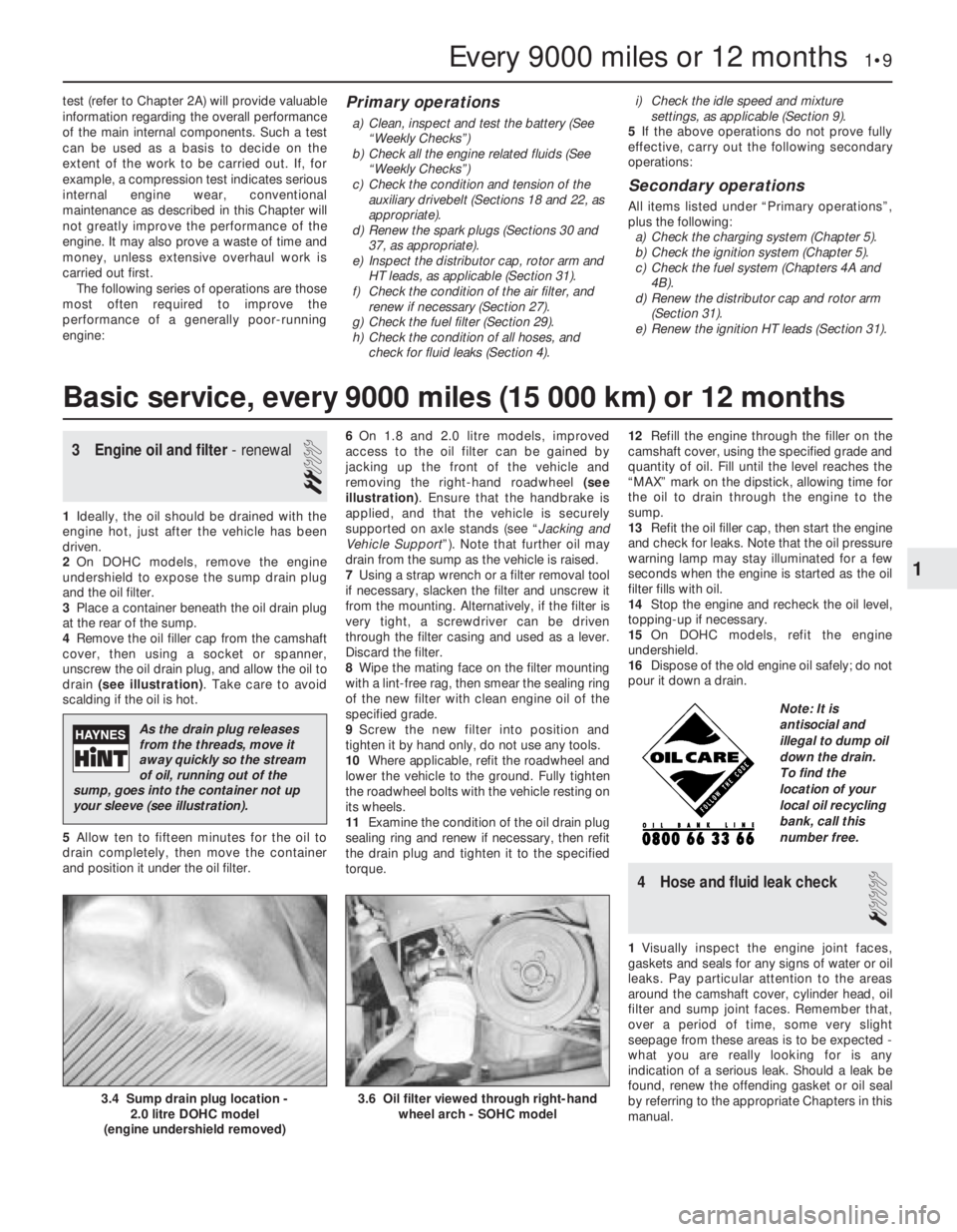
4Remove the oil filler cap from the camshaft
cover, then using a socket or spanner,
unscrew the oil drain plug, and allow the oil to
drain (see illustration). Take care to avoid
scalding if the oil is hot.
5Allow ten to fifteen minutes for the oil to
drain completely, then move the container
and position it under the oil filter.6On 1.8 and 2.0 litre models, improved
access to the oil filter can be gained by
jacking up the front of the vehicle and
removing the right-hand roadwheel (see
illustration). Ensure that the handbrake is
applied, and that the vehicle is securely
supported on axle stands (see “Jacking and
Vehicle Support”). Note that further oil may
drain from the sump as the vehicle is raised.
7Using a strap wrench or a filter removal tool
if necessary, slacken the filter and unscrew it
from the mounting. Alternatively, if the filter is
very tight, a screwdriver can be driven
through the filter casing and used as a lever.
Discard the filter.
8Wipe the mating face on the filter mounting
with a lint-free rag, then smear the sealing ring
of the new filter with clean engine oil of the
specified grade.
9Screw the new filter into position and
tighten it by hand only, do not use any tools.
10Where applicable, refit the roadwheel and
lower the vehicle to the ground. Fully tighten
the roadwheel bolts with the vehicle resting on
its wheels.
11Examine the condition of the oil drain plug
sealing ring and renew if necessary, then refit
the drain plug and tighten it to the specified
torque. 12Refill the engine through the filler on the
camshaft cover, using the specified grade and
quantity of oil. Fill until the level reaches the
“MAX” mark on the dipstick, allowing time for
the oil to drain through the engine to the
sump.
13Refit the oil filler cap, then start the engine
and check for leaks. Note that the oil pressure
warning lamp may stay illuminated for a few
seconds when the engine is started as the oil
filter fills with oil.
14Stop the engine and recheck the oil level,
topping-up if necessary.
15On DOHC models, refit the engine
undershield.
16Dispose of the old engine oil safely; do not
pour it down a drain.
4Hose and fluid leak check
1
1Visually inspect the engine joint faces,
gaskets and seals for any signs of water or oil
leaks. Pay particular attention to the areas
around the camshaft cover, cylinder head, oil
filter and sump joint faces. Remember that,
over a period of time, some very slight
seepage from these areas is to be expected -
what you are really looking for is any
indication of a serious leak. Should a leak be
found, renew the offending gasket or oil seal
by referring to the appropriate Chapters in this
manual.
Every 9000 miles or 12 months 1•9
3.6 Oil filter viewed through right-hand
wheel arch - SOHC model3.4 Sump drain plug location -
2.0 litre DOHC model
(engine undershield removed)
1
Basic service, every 9000 miles (15 000 km) or 12 months
As the drain plug releases
from the threads, move it
away quickly so the stream
of oil, running out of the
sump, goes into the container not up
your sleeve (see illustration).
Note: It is
antisocial and
illegal to dump oil
down the drain.
To find the
location of your
local oil recycling
bank, call this
number free.
Page 185 of 525
28Air inlet temperature control
check (carburettor models
only)
2
Refer to Chapter 4A for details.
29Fuel filter renewal
3
Fuel filters are fitted in various locations
throughout the range. Some may be ‘in-line’ in
the fuel tank itself, or fitted into the
carburettor.
Refer to Chapters 4A or 4B, as appropriate.
30Spark plug renewal (SOHC)
2
1The correct functioning of the spark plugs is
vital for the correct running and efficiency of
the engine. It is essential that the plugs fitted
are appropriate for the engine. Refer to the
specifications in Chapter 5. If this type is used
and the engine is in good condition, the spark
plugs should not need attention between
scheduled service replacement intervals.
Spark plug cleaning is rarely necessary and
should not be attempted unless specialised
equipment is available, as damage can easily
be caused to the firing ends.
2Identify each HT lead for position so that the
leads can be refitted to their correct cylinders.
Then disconnect the leads from the plugs by
pulling on the connectors, not the leads.
3Clean the area around each spark plug
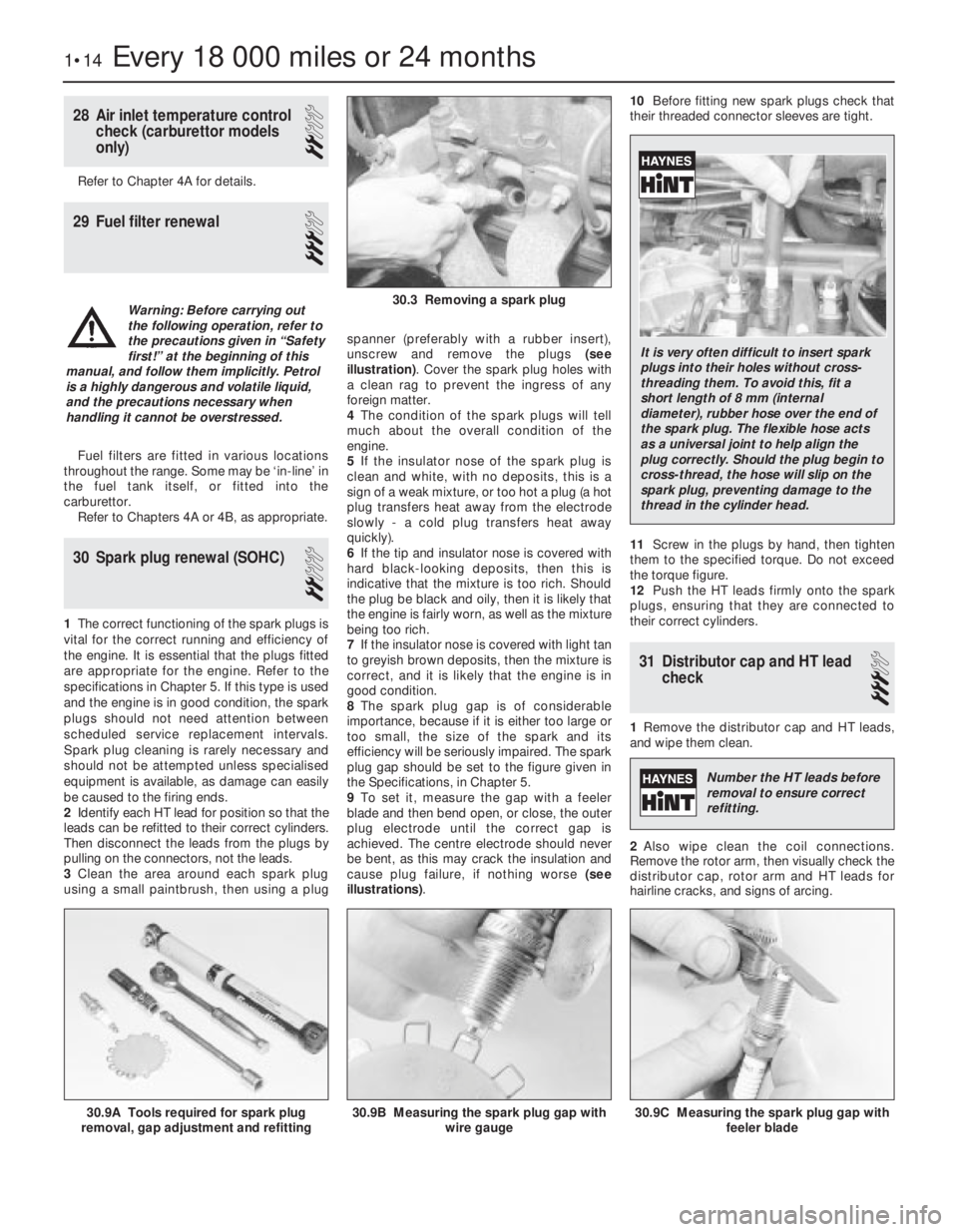
using a small paintbrush, then using a plugspanner (preferably with a rubber insert),
unscrew and remove the plugs (see
illustration). Cover the spark plug holes with
a clean rag to prevent the ingress of any
foreign matter.
4The condition of the spark plugs will tell
much about the overall condition of the
engine.
5If the insulator nose of the spark plug is
clean and white, with no deposits, this is a
sign of a weak mixture, or too hot a plug (a hot
plug transfers heat away from the electrode
slowly -a cold plug transfers heat away
quickly).
6If the tip and insulator nose is covered with
hard black-looking deposits, then this is
indicative that the mixture is too rich. Should
the plug be black and oily, then it is likely that
the engine is fairly worn, as well as the mixture
being too rich.
7If the insulator nose is covered with light tan
to greyish brown deposits, then the mixture is
correct, and it is likely that the engine is in
good condition.
8The spark plug gap is of considerable
importance, because if it is either too large or
too small, the size of the spark and its
efficiency will be seriously impaired. The spark
plug gap should be set to the figure given in
the Specifications, in Chapter 5.
9To set it, measure the gap with a feeler
blade and then bend open, or close, the outer
plug electrode until the correct gap is
achieved. The centre electrode should never
be bent, as this may crack the insulation and
cause plug failure, if nothing worse (see
illustrations).10Before fitting new spark plugs check that
their threaded connector sleeves are tight.
11Screw in the plugs by hand, then tighten
them to the specified torque. Do not exceed
the torque figure.
12Push the HT leads firmly onto the spark
plugs, ensuring that they are connected to
their correct cylinders.
31Distributor cap and HT lead
check
3
1Remove the distributor cap and HT leads,
and wipe them clean.
2Also wipe clean the coil connections.
Remove the rotor arm, then visually check the
distributor cap, rotor arm and HT leads for
hairline cracks, and signs of arcing.
1•14Every 18 000 miles or 24 months
30.9A Tools required for spark plug
removal, gap adjustment and refitting30.9C Measuring the spark plug gap with
feeler blade30.9B Measuring the spark plug gap with
wire gauge
30.3 Removing a spark plugWarning: Before carrying out
the following operation, refer to
the precautions given in “Safety
first!” at the beginning of this
manual, and follow them implicitly. Petrol
is a highly dangerous and volatile liquid,
and the precautions necessary when
handling it cannot be overstressed.
It is very often difficult to insert spark
plugs into their holes without cross-
threading them. To avoid this, fit a
short length of 8 mm (internal
diameter), rubber hose over the end of
the spark plug. The flexible hose acts
as a universal joint to help align the
plug correctly. Should the plug begin to
cross-thread, the hose will slip on the
spark plug, preventing damage to the
thread in the cylinder head.
Number the HT leads before
removal to ensure correct
refitting.
Page 198 of 525
2A
General
Type
All models . . . . . . . . . . . . . . . . . . . . . . . . . . . . . . . . . . . . . . . . . . . . . . Four-cylinder, in-line, water-cooled, transversely mounted at front of
vehicle. Single belt-driven overhead camshaft, acting on hydraulic
valve lifters
Manufacturer’s engine codes:
14 NV . . . . . . . . . . . . . . . . . . . . . . . . . . . . . . . . . . . . . . . . . . . . . . . . . 1.4 litre (1389 cc)
16 SV . . . . . . . . . . . . . . . . . . . . . . . . . . . . . . . . . . . . . . . . . . . . . . . . . . 1.6 litre (1598 cc)
X16 SZ . . . . . . . . . . . . . . . . . . . . . . . . . . . . . . . . . . . . . . . . . . . . . . . . 1.6 litre (1598 cc) ‘Ecotec’ type engine
C16 NZ . . . . . . . . . . . . . . . . . . . . . . . . . . . . . . . . . . . . . . . . . . . . . . . . 1.6 litre (1598 cc) + catalyst
C16 NZ2 . . . . . . . . . . . . . . . . . . . . . . . . . . . . . . . . . . . . . . . . . . . . . . . 1.6 litre (1598 cc) + catalyst
18 SV . . . . . . . . . . . . . . . . . . . . . . . . . . . . . . . . . . . . . . . . . . . . . . . . . . 1.8 litre (1796 cc)
C18 NZ . . . . . . . . . . . . . . . . . . . . . . . . . . . . . . . . . . . . . . . . . . . . . . . . 1.8 litre (1796 cc) + catalyst
20 NE . . . . . . . . . . . . . . . . . . . . . . . . . . . . . . . . . . . . . . . . . . . . . . . . . 2.0 litre (1998 cc)
20 SEH . . . . . . . . . . . . . . . . . . . . . . . . . . . . . . . . . . . . . . . . . . . . . . . . 2.0 litre (1998 cc) + early SRi
C20 NE . . . . . . . . . . . . . . . . . . . . . . . . . . . . . . . . . . . . . . . . . . . . . . . . 2.0 litre (1998 cc) + catalyst
Pistons:Bore (mm) Stroke (mm)
14 NV . . . . . . . . . . . . . . . . . . . . . . . . . . . . . . . . . . . . . . . . . . . . . . . . . 77.6 73.4
16 SV, C16 SV, C16 NZ and X16 SZ . . . . . . . . . . . . . . . . . . . . . . . . . 79.0 81.5
C16 NZ2 . . . . . . . . . . . . . . . . . . . . . . . . . . . . . . . . . . . . . . . . . . . . . . . 80.0 79.5
18 SV and C18 NZ . . . . . . . . . . . . . . . . . . . . . . . . . . . . . . . . . . . . . . . 84.8 79.5
20 NE, 20 SEH and C20 NE . . . . . . . . . . . . . . . . . . . . . . . . . . . . . . . . 86.0 86.0
Chapter 2 Part A:
SOHC engine procedures
Camshaft front oil seal - removal and refitting . . . . . . . . . . . . . . . . . .15
Camshaft housing and camshaft - general . . . . . . . . . . . . . . . . . . . .17
Camshaft housing and camshaft - dismantling, inspection and
reassembly . . . . . . . . . . . . . . . . . . . . . . . . . . . . . . . . . . . . . . . . . . .18
Camshaft rear oil seal - removal and refitting . . . . . . . . . . . . . . . . . . .16
Camshafts, “undersize” C16 NZ2, 1.8 and 2.0 litre engines -
general . . . . . . . . . . . . . . . . . . . . . . . . . . . . . . . . . . . . . . . . . . . . . .19
Compression test - description . . . . . . . . . . . . . . . . . . . . . . . . . . . . . .3
Crankcase ventilation system - description and maintenance . . . . . . .2
Crankshaft and bearings - examination . . . . . . . . . . . . . . . . . . . . . . .35
Crankshaft and bearings - removal and refitting . . . . . . . . . . . . . . . .34
Crankshaft front oil seal - renewal . . . . . . . . . . . . . . . . . . . . . . . . . . .27
Crankshaft rear oil seal - renewal . . . . . . . . . . . . . . . . . . . . . . . . . . . .28
Cylinder block and bores - examination and renovation . . . . . . . . . .36
Cylinder head - dismantling and reassembly . . . . . . . . . . . . . . . . . . .22
Cylinder head - inspection and renovation . . . . . . . . . . . . . . . . . . . . .23
Cylinder head - removal and refitting (engine in vehicle) . . . . . . . . . .20
Cylinder head - removal and refitting (engine removed) . . . . . . . . . . .21
Engine - removal and refitting (leaving transmission in car) . . . . . . . . .7
Engine and transmission mountings - renewal . . . . . . . . . . . . . . . . . . .9
Engine and transmission - removal, separation, reconnection and
refitting . . . . . . . . . . . . . . . . . . . . . . . . . . . . . . . . . . . . . . . . . . . . . . .8
Engine oil and filter - renewal . . . . . . . . . . . . . . . . . . . . .See Chapter 1Engine dismantling and reassembly - general . . . . . . . . . . . . . . . . . .10
Examination and renovation - general . . . . . . . . . . . . . . . . . . . . . . . .37
Flexplate (automatic transmission) - removal and refitting . . . . . . . . .26
Flywheel - removal, inspection and refitting . . . . . . . . . . . . . . . . . . . .25
General description . . . . . . . . . . . . . . . . . . . . . . . . . . . . . . . . . . . . . . .1
Hydraulic valve lifters - inspection . . . . . . . . . . . . . . . . . . . . . . . . . . .24
Initial start-up after major overhaul or repair . . . . . . . . . . . . . . . . . . .38
Major operations possible with the engine in the vehicle . . . . . . . . . . .4
Major operations requiring engine removal . . . . . . . . . . . . . . . . . . . . .5
Method of engine removal . . . . . . . . . . . . . . . . . . . . . . . . . . . . . . . . . .6
Oil pump - dismantling, inspection and reassembly . . . . . . . . . . . . .31
Oil pump - removal and refitting . . . . . . . . . . . . . . . . . . . . . . . . . . . . .30
Pistons and connecting rods - examination and renovation . . . . . . .33
Pistons and connecting rods - removal and refitting . . . . . . . . . . . . .32
Sump - removal and refitting . . . . . . . . . . . . . . . . . . . . . . . . . . . . . . .29
Timing belt and sprockets (without automatic tensioner) - removal,
refitting and adjustment . . . . . . . . . . . . . . . . . . . . . . . . . . . . . . . . .11
Timing belt and tensioner 1.4 and 1.6 models (not C16 NZ2) - removal,
refitting and adjustment . . . . . . . . . . . . . . . . . . . . . . . . . . . . . . . . .12
Timing belt and tensioner C16 NZ2, 1.8 and 2.0 litre - removal, refitting
and adjustment . . . . . . . . . . . . . . . . . . . . . . . . . . . . . . . . . . . . . . . .14
Timing belt cover aperture, 1.4 and 1.6 models - general . . . . . . . . .13
2A•1
Specifications Contents
Easy,suitable for
novice with little
experienceFairly easy,suitable
for beginner with
some experienceFairly difficult,
suitable for competent
DIY mechanic
Difficult,suitable for
experienced DIY
mechanicVery difficult,
suitable for expert DIY
or professional
Degrees of difficulty
54321
Page 204 of 525
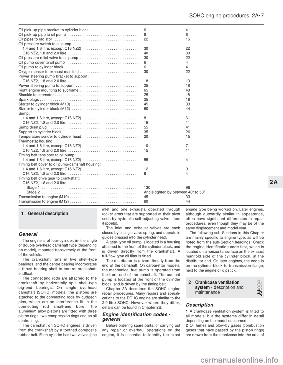
Oil pick-up pipe bracket to cylinder block . . . . . . . . . . . . . . . . . . . . . . .64
Oil pick-up pipe to oil pump . . . . . . . . . . . . . . . . . . . . . . . . . . . . . . . . . .86
Oil pipes to radiator . . . . . . . . . . . . . . . . . . . . . . . . . . . . . . . . . . . . . . . .2216
Oil pressure switch to oil pump:
1.4 and 1.6 litre, (except C16 NZ2) . . . . . . . . . . . . . . . . . . . . . . . . . .3022
C16 NZ2, 1.8 and 2.0 litre . . . . . . . . . . . . . . . . . . . . . . . . . . . . . . . . . .4030
Oil pressure relief valve to oil pump . . . . . . . . . . . . . . . . . . . . . . . . . . . .3022
Oil pump cover to oil pump . . . . . . . . . . . . . . . . . . . . . . . . . . . . . . . . . .64
Oil pump to cylinder block . . . . . . . . . . . . . . . . . . . . . . . . . . . . . . . . . . .64
Oxygen sensor to exhaust manifold . . . . . . . . . . . . . . . . . . . . . . . . . . . .3022
Power steering pump bracket to support:
C16 NZ2, 1.8 and 2.0 litre . . . . . . . . . . . . . . . . . . . . . . . . . . . . . . . . . .1813
Power steering pump to support . . . . . . . . . . . . . . . . . . . . . . . . . . . . . .2518
Right engine mounting to subframe . . . . . . . . . . . . . . . . . . . . . . . . . . . .6548
Shackle to alternator . . . . . . . . . . . . . . . . . . . . . . . . . . . . . . . . . . . . . . . .2518
Spark plugs . . . . . . . . . . . . . . . . . . . . . . . . . . . . . . . . . . . . . . . . . . . . . . .2518
Starter to cylinder block (M10) . . . . . . . . . . . . . . . . . . . . . . . . . . . . . . . .4533
Starter to cylinder block (M12) . . . . . . . . . . . . . . . . . . . . . . . . . . . . . . . .6044
Sump:
1.4 and 1.6 litre, (except C16 NZ2) . . . . . . . . . . . . . . . . . . . . . . . . . . .86
C16 NZ2, 1.8 and 2.0 litre . . . . . . . . . . . . . . . . . . . . . . . . . . . . . . . . . .1511
Sump drain plug . . . . . . . . . . . . . . . . . . . . . . . . . . . . . . . . . . . . . . . . . . .5541
Support to cylinder block . . . . . . . . . . . . . . . . . . . . . . . . . . . . . . . . . . . .3526
Temperature sender to cylinder head . . . . . . . . . . . . . . . . . . . . . . . . . . .2015
Thermostat housing:
1.4 and 1.6 litre, (except C16 NZ2) . . . . . . . . . . . . . . . . . . . . . . . . . . .107
C16 NZ2, 1.8 and 2.0 litre . . . . . . . . . . . . . . . . . . . . . . . . . . . . . . . . . .1511
Timing belt tensioner to oil pump:
1.4 and 1.6 litre, (except C16 NZ2) . . . . . . . . . . . . . . . . . . . . . . . . . . .5541
Timing belt cover to oil pump/camshaft housing:
1.4 and 1.6 litre, (except C16 NZ2) . . . . . . . . . . . . . . . . . . . . . . . . . . .129
C16 NZ2, 1.8 and 2.0 litre . . . . . . . . . . . . . . . . . . . . . . . . . . . . . . . . . .64
Timing belt drive gear to crankshaft:
C16 NZ2, 1.8 and 2.0 litre:
Stage 1 . . . . . . . . . . . . . . . . . . . . . . . . . . . . . . . . . . . . . . . . . . . . . .13096
Stage 2 . . . . . . . . . . . . . . . . . . . . . . . . . . . . . . . . . . . . . . . . . . . . . .Angle tighten by between 40º to 50º
Transmission to engine (M10) . . . . . . . . . . . . . . . . . . . . . . . . . . . . . . . . .4533
Transmission to engine (M12) . . . . . . . . . . . . . . . . . . . . . . . . . . . . . . . . .6044
1General description
General
The engine is of four-cylinder, in-line single
or double overhead camshaft type (depending
on model), mounted transversely at the front
of the vehicle.
The crankshaft runs in five shell-type
bearings, and the centre bearing incorporates
a thrust bearing shell to control crankshaft
endfloat.
The connecting rods are attached to the
crankshaft by horizontally split shell-type
big-end bearings. On single overhead
camshaft (SOHC) models, the pistons are
attached to the connecting rods by gudgeon
pins, which are an interference fit in the
connecting rod small-end bore. The
aluminium alloy pistons are fitted with three
piston rings: two compression rings and an oil
control ring.
The camshaft on SOHC engines is driven
from the crankshaft by a toothed composite
rubber belt. Each cylinder has two valves (oneinlet and one exhaust), operated through
rocker arms that are supported at their pivot
ends by hydraulic self-adjusting valve lifters
(tappets).
The inlet and exhaust valves are each
closed by a single valve spring, and operate in
guides pressed into the cylinder head.
A gear-type oil pump is located in a housing
attached to the front of the cylinder block, and
is driven directly from the crankshaft. A
full-flow type oil filter is fitted.
The distributor is driven directly from the
end of the camshaft. On carburettor models,
the mechanical fuel pump is operated from
the front end of the camshaft. The coolant
pump is located at the front of the cylinder
block, and is driven by the timing belt.
Chapter 2A describes the SOHC engine
repair procedures. Many repairs and specifi-
cations to the DOHC engine are similar to the
2.0 litre SOHC. However where they differ,
details can be found in Chapter 2B.
Engine identification codes -
general
Before ordering spare parts, or carrying out
any repair or overhaul operations on the
engine, it is essential to identify the exactengine type being worked on. Later engines,
although outwardly similar in appearance,
often have significant differences in repair
procedures, even though they may be of the
same displacement and model year.
The following sub-Sections in this Chapter
are mainly specific to engine type, as will be
noted from the sub-Section headings. Check
the engine identification code first, which is
located on a horizontal surface on the exhaust
manifold side of the cylinder block, at the
distributor end. On later engines, the code is
on the cylinder block-to-transmission flange,
next to the engine oil dipstick.
2Crankcase ventilation
system - description and
maintenance
2
Description
1A crankcase ventilation system is fitted to
all models, but the systems differ in detail
depending on the model concerned.
2Oil fumes and blow-by gases (combustion
gases that have passed by the piston rings)
are drawn from the crankcase into the area of
SOHC engine procedures 2A•7
2A
Page 205 of 525
the cylinder head above the camshaft(s)
through a hose. From here the gases are
drawn into the inlet manifold/throttle body (as
applicable) and/or the air box on the
carburettor (where applicable), where they are
re-burnt with fresh air/fuel mixture, hence
reducing harmful exhaust emissions.
Maintenance
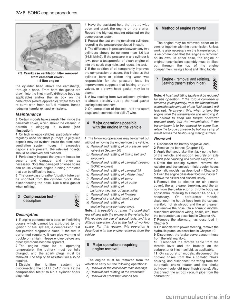
3Certain models have a mesh filter inside the
camshaft cover, which should be cleaned in
paraffin if clogging is evident (see
illustration).
4On high mileage vehicles, particularly when
regularly used for short journeys, a jelly-like
deposit may be evident inside the crankcase
ventilation system hoses. If excessive
deposits are present, the relevant hose(s)
should be removed and cleaned.
5Periodically inspect the system hoses for
security and damage, and renew as
necessary. Note that damaged or loose hoses
can cause various engine running problems
that can be difficult to trace.
6The crankcase breather/dipstick tube can
be unbolted from the cylinder block after
disconnecting the hose. Use a new gasket
when refitting.
3Compression test -
description
3
Description
1If engine performance is poor, or if misfiring
occurs which cannot be attributed to the
ignition or fuel system, a compression test
can provide diagnostic clues. If the test is
performed regularly, it can give warning of
trouble on a high mileage engine before any
other symptoms become apparent.
2The engine must be at operating
temperature, the battery must be fully
charged, and the spark plugs must be
removed. The help of an assistant will also be
required.
3Disable the ignition system by
disconnecting the coil LT (“+15”) wire. Fit the
compression tester to No 1 cylinder spark
plug hole.4Have the assistant hold the throttle wide
open and crank the engine on the starter.
Record the highest reading obtained on the
compression tester.
5Repeat the test on the remaining cylinders,
recording the pressure developed in each.
6The difference in pressure between any two
cylinders should be no more than 1.0 bar
(14.5 lbf/in2). If the pressure in any cylinder is
low, pour a teaspoonful of clean engine oil
into the spark plug hole, and repeat the test.
7If the addition of oil temporarily improves
the compression pressure, this indicates that
cylinder bore or piston ring wear was
responsible for the pressure loss. No
improvement suggests that leaking or burnt
valves, or a blown head gasket may be to
blame.
8A low reading from two adjacent cylinders
is almost certainly due to the head gasket
leaking between them.
9On completion of the test, refit the spark
plugs and reconnect the coil LT wire.
4Major operations possible
with the engine in the vehicle
1The following operations may be carried out
without removing the engine from the vehicle:
a)Removal and refitting of oil pressure relief
valve (see Section 30)
b)Removal and refitting of timing belt and
sprockets
c)Removal and refitting of camshaft housing
(SOHC engines)
d)Removal and refitting of camshaft(s)
e)Removal and refitting of cylinder head
f)Removal and refitting of sump
g)Removal and refitting of oil pump
h)Removal and refitting of
piston/connecting rod assemblies
i)Removal and refitting of flywheel
j)Renewal of crankshaft front oil seal
k)Removal and refitting of
engine/transmission mountings
Note: It is possible to renew the crankshaft
rear oil seal with the engine in the vehicle, but
this requires the use of special tools, and is a
difficult operation, due to the lack of working
space. For this reason, this operation is
described with the engine removed from the
vehicle.
5Major operations requiring
engine removal
The engine must be removed from the
vehicle to carry out the following operations:
a)Renewal of the crankshaft main bearings
b)Removal and refitting of the crankshaft
c)Renewal of crankshaft rear oil seal
6Method of engine removal
The engine may be removed either on its
own, or together with the transmission. Unless
work is also necessary on the transmission, it
is recommended that the engine is removed
on its own. In either case, the engine or
engine/transmission assembly must be lifted
out through the top of the engine
compartment, using a hoist and lifting tackle.
7Engine - removal and refitting,
(leaving transmission in car)
4
Note: A hoist and lifting tackle will be required
for this operation.If the torque converter is
removed (even partially) from the transmission,
a considerable amount of the fluid inside it will
leak out. To prevent this, when prising the
engine from the transmission and removing it,
be careful to keep the torque converter
pressed firmly into the transmission. If the
transmission is to be removed for some time,
retain the torque converter by bolting a strip of
metal across the bellhousing mating surface.
Removal
1Disconnect the battery negative lead.
2Remove the bonnet (Chapter 11).
3Apply the handbrake, then jack up the front
of the vehicle, and support securely on axle
stands (see “Jacking and Vehicle Support”).
4Drain the cooling system, remove the
radiator and transmission fluid cooler hoses
(automatic models), as described in Chapter 3.
5Drain the engine oil as described in Chapter 1,
remove the oil filter and discard, safely.
6Remove the air cleaner (or air cleaner
cover), the air cleaner trunking, and the air
box from the carburettor or throttle body (as
applicable), referring to Chapter 4A or 4B, if
necessary. On carburettor models,
disconnect the hot air hose from the exhaust
manifold hot air shroud and the air cleaner,
and remove the hose. On automatic models,
disconnect additional wiring, hoses, etc., from
the carburettor, as described in Chapter 4A.
7Remove the alternator, as described in
Chapter 5.
8On models with power steering, remove the
hydraulic pump, as described in Chapter 10.
9Disconnect the brake servo vacuum hose
from the inlet manifold.
10Disconnect the throttle cable from the
throttle lever and the bracket on the
carburettor or inlet manifold, as applicable.
11On carburettor models, disconnect the
coolant hoses from the automatic choke
housing, and disconnect the wiring from the
automatic choke heater and the choke
pull-down solenoid (see illustrations). Also
disconnect the air box vacuum pipe from the
carburettor.
2A•8SOHC engine procedures
2.3 Crankcase ventilation filter removed
from camshaft cover -
1.6 litre engine
Page 207 of 525
30With the engine removed, the
transmission can be supported by placing a
length of wood between the bellhousing and
the front suspension subframe. Once the
wooden support is in place, remove the trolley
jack from under the transmission.
Refitting
Note: New left and right-hand
engine/transmission mounting-to-body bolts
must be used on refitting.
31Use an M10 x 1.25 bottoming tap to clean
the threads in the torque converters threaded
bosses and ensure that new bolts are
available for reassembly, where applicable.
32Support the transmission with a trolley
jack and remove the length of wood from
between the bellhousing and the subframe.
33Support the engine with the hoist and
lifting tackle, and gently lower it into position
in the engine compartment.
34Mate the engine and transmission
together, ensuring that the transmission
locates on the dowels in the cylinder block,
then refit the three upper
engine-to-transmission bolts.
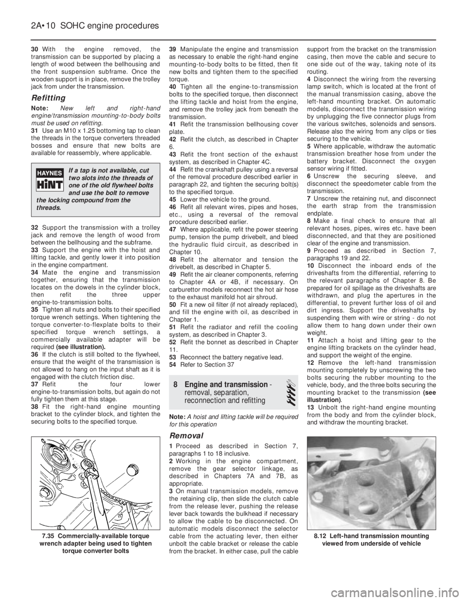
35Tighten all nuts and bolts to their specified
torque wrench settings. When tightening the
torque converter-to-flexplate bolts to their
specified torque wrench settings, a
commercially available adapter will be
required (see illustration).
36If the clutch is still bolted to the flywheel,
ensure that the weight of the transmission is
not allowed to hang on the input shaft as it is
engaged with the clutch friction disc.
37Refit the four lower
engine-to-transmission bolts, but again do not
fully tighten them at this stage.
38Fit the right-hand engine mounting
bracket to the cylinder block, and tighten the
securing bolts to the specified torque.39Manipulate the engine and transmission
as necessary to enable the right-hand engine
mounting-to-body bolts to be fitted, then fit
new bolts and tighten them to the specified
torque.
40Tighten all the engine-to-transmission
bolts to the specified torque, then disconnect
the lifting tackle and hoist from the engine,
and remove the trolley jack from beneath the
transmission.
41Refit the transmission bellhousing cover
plate.
42Refit the clutch, as described in Chapter
6.
43Refit the front section of the exhaust
system, as described in Chapter 4C.
44Refit the crankshaft pulley using a reversal
of the removal procedure described earlier in
paragraph 22, and tighten the securing bolt(s)
to the specified torque.
45Lower the vehicle to the ground.
46Refit all relevant wires, pipes and hoses,
etc., using a reversal of the removal
procedure described earlier.
47Where applicable, refit the power steering
pump, tension the pump drivebelt, and bleed
the hydraulic fluid circuit, as described in
Chapter 10.
48Refit the alternator and tension the
drivebelt, as described in Chapter 5.
49Refit the air cleaner components, referring
to Chapter 4A or 4B, if necessary. On
carburettor models reconnect the hot air hose
to the exhaust manifold hot air shroud.
50Fit a new oil filter (if not already replaced),
and fill the engine with oil, as described in
Chapter 1.
51Refit the radiator and refill the cooling
system, as described in Chapter 3.
52Refit the bonnet as described in Chapter
11.
53Reconnect the battery negative lead.
54Refer to Section 37
8Engine and transmission -
removal, separation,
reconnection and refitting
4
Note: A hoist and lifting tackle will be required
for this operation
Removal
1Proceed as described in Section 7,
paragraphs 1 to 18 inclusive.
2Working in the engine compartment,
remove the gear selector linkage, as
described in Chapters 7A and 7B, as
appropriate.
3On manual transmission models, remove
the retaining clip, then slide the clutch cable
from the release lever, pushing the release
lever back towards the bulkhead if necessary
to allow the cable to be disconnected. On
automatic models disconnect the selector
cable from the actuating lever, then either
unbolt the cable bracket or release the cable
from the bracket. In either case, pull the cablesupport from the bracket on the transmission
casing, then move the cable and secure to
one side out of the way, taking note of its
routing.
4Disconnect the wiring from the reversing
lamp switch, which is located at the front of
the manual transmission casing, above the
left-hand mounting bracket. On automatic
models, disconnect the transmission wiring
by unplugging the five connector plugs from
the various switches, solenoids and sensors.
Release also the wiring from any clips or ties
securing to the vehicle.
5Where applicable, withdraw the automatic
transmission breather hose from under the
battery bracket. Disconnect the oxygen
sensor wiring if fitted.
6Unscrew the securing sleeve, and
disconnect the speedometer cable from the
transmission.
7Unscrew the retaining nut, and disconnect
the earth strap from the transmission
endplate.
8Make a final check to ensure that all
relevant hoses, pipes, wires etc. have been
disconnected, and that they are positioned
clear of the engine and transmission.
9Proceed as described in Section 7,
paragraphs 19 and 22.
10Disconnect the inboard ends of the
driveshafts from the differential, referring to
the relevant paragraphs of Chapter 8. Be
prepared for oil spillage as the driveshafts are
withdrawn, and plug the apertures in the
differential, to prevent further loss of oil and
dirt ingress. Support the driveshafts by
suspending them with wire or string - do not
allow them to hang down under their own
weight.
11Attach a hoist and lifting gear to the
engine lifting brackets on the cylinder head,
and support the weight of the engine.
12Remove the left-hand transmission
mounting completely by unscrewing the two
bolts securing the rubber mounting to the
vehicle, body, and the three bolts securing the
mounting bracket to the transmission (see
illustration).
13Unbolt the right-hand engine mounting
from the body and from the cylinder block,
and withdraw the mounting bracket.
2A•10SOHC engine procedures
8.12 Left-hand transmission mounting
viewed from underside of vehicle7.35 Commercially-available torque
wrench adapter being used to tighten
torque converter bolts
If a tap is not available, cut
two slots into the threads of
one of the old flywheel bolts
and use the bolt to remove
the locking compound from the
threads.
Page 231 of 525
5Note that the rubber plug located next to
the bellhousing flange on the cylinder block
covers the aperture for the installation of a
diagnostic TDC sensor. The sensor, when
connected to a monitoring unit, indicates TDC
from the position of the pins set into the
crankshaft balance weight.
37Examination and renovation
-general
4
General
1With the engine completely stripped, clean all
components and examine them for wear. Each
component should be checked, and where
necessary renewed or renovated, as described
in the relevant Sections of this Chapter.
2Renew main and big-end bearing shells as
a matter of course, unless it is known that
they have had little wear, and are in perfect
condition.
3If in doubt whether to renew a component
that is still just serviceable, consider the time
and effort that will be incurred should the
component fail at an early date after rebuild.
Obviously, the age and expected life of the
vehicle must influence the standards applied.4Gaskets, oil seals and O-rings must all be
renewed as a matter of routine. Flywheel,
cylinder head, and main and big-end bearing
cap bolts must be renewed, because of the
high stress to which they are subjected.
5Renew the engine core plugs while they are
easily accessible, if they show signs of
leakage. Knock out the old plugs with a
hammer and chisel or punch. Clean the plug
seats, smear the new plugs with sealing
compound, and tap them squarely into
position.
38Initial start-up after major
overhaul or repair
2
1Make a final check to ensure that
everything has been reconnected to the
engine, and that no rags or tools have been
left in the engine compartment.
2Check that oil and coolant levels are
correct.
3Start the engine. This may take a little longer
than usual, as fuel is pumped to the engine.
4Check that the oil pressure warning lamp
goes out when the engine starts. This may
take a few seconds as the new oil filter fills
with oil.5Run the engine at a fast tickover, and check
for leaks of oil, fuel and coolant. If a new
camshaft has been fitted, pay careful
attention to the running-in procedure given in
Section 18, paragraphs 17 and 18. Where
applicable, check the power steering and/or
automatic transmission fluid cooler unions for
leakage. Some smoke and odd smells may be
experienced, as assembly lubricants and
sealers burn off the various components.
6Bring the engine to normal operating
temperature. Check the ignition timing, idle
speed and the mixture (where applicable), as
described in Chapter 4A or 4B.
7Allow the engine to cool, then recheck the
oil and coolant levels. Top-up if necessary
8If new bearings, pistons, etc., have been
fitted, the engine should be run-in at reduced
speeds and loads for the first 500 miles (800
km) or so. It is beneficial to change the engine
oil and filter after this mileage.
2A•34SOHC engine procedures