1988 OPEL CALIBRA octane
[x] Cancel search: octanePage 156 of 525

4B
cruising and accelerating. The injector earth is
also switched off on the overrun to improve
fuel economy and reduce exhaust emissions.
Additionally, on the X16 SZ engine, the ECU
also controls the operation of the charcoal
canister purge valve in the evaporative
emission control system.
10The oxygen sensor screwed into the
exhaust manifold provides the ECU with a
constant feedback signal. This enables it to
adjust the mixture (closed-loop control) to
provide the best possible conditions for the
catalytic converter to operate effectively.
11Until the oxygen sensor is fully warmed up
it gives no feedback so the ECU uses
pre-programmed values (open-loop control) to
determine the correct injector pulse width.
When the sensor reaches its normal operating
temperature, its tip (which is sensitive to
oxygen) sends the ECU a varying voltage
depending on the amount of oxygen in the
exhaust gases. If the inlet air/fuel mixture is too
rich, the exhaust gases are low in oxygen so the
sensor sends a low-voltage signal. The voltage
rises as the mixture weakens and the amount of
oxygen rises in the exhaust gases. Peak
conversion efficiency of all major pollutants
occurs if the inlet air/fuel mixture is maintained
at the chemically correct ratio for the complete
combustion of petrol of 14.7 parts (by weight) of
air to 1 part of fuel (the “stoichiometric” ratio).
The sensor output voltage alters in a large step
at this point, the ECU using the signal change
as a reference point and correcting the inlet
air/fuel mixture accordingly by altering the fuel
injector pulse width.
12In addition, the ECU senses battery
voltage, incorporates diagnostic capabilities,
and can both receive and transmit information
by way of the diagnostic connector, thus
permitting engine diagnosis and tuning by
Vauxhall’s TECH1, test equipment.
Motronic system
13The Motronic type is available in several
different versions, depending on model. The
system is under the overall control of the
Motronic engine management system (Chapter
5), which also controls the ignition timing.
14Fuel is supplied from the rear-mounted
fuel tank by an electric fuel pump mounted
under the rear of the vehicle, through a
pressure regulator, to the fuel rail. The fuel rail
acts as a reservoir for the four fuel injectors,
which inject fuel into the cylinder inlet tracts,
upstream of the inlet valves. On SOHC
engines, the fuel injectors receive an electrical
pulse once per crankshaft revolution, which
operates all four injectors simultaneously. On
DOHC engines, sequential fuel injection is
used, whereby each injector receives an
individual electrical pulse allowing the four
injectors to operate independently, which
enables finer control of the fuel supply to each
cylinder. The duration of the electrical pulse
determines the quantity of fuel-injected, and
pulse duration is computed by the Motronic
module, based on the information received
from the various sensors.15On SOHC engines, inlet air passes from
the air cleaner through a vane type airflow
meter, before passing to the cylinder inlet
tracts through the throttle valve. A flap in the
vane airflow meter is deflected in proportion
to the airflow; this deflection is converted into
an electrical signal, and passed to the
Motronic module. A potentiometer screw
located on the airflow meter provides the
means of idle mixture adjustment, by altering
the reference voltage supplied to the Motronic
module.
16On DOHC engines, inlet air passes from
the air cleaner through a hot wire type air
mass meter, before passing to the cylinder
inlet tracts through a two-stage throttle body
assembly. The electrical current required to
maintain the temperature of the hot wire in the
air mass meter is directly proportional to the
mass flow rate of the air trying to cool it. The
current is converted into a signal, which is
passed to the Motronic module. The throttle
body contains two throttle valves that open
progressively, allowing high torque at part
throttle, and full-throttle, high-speed
“breathing” capacity. A potentiometer screw
located on the air mass meter provides the
means of idle mixture adjustment, by altering
the reference voltage supplied to the Motronic
module.
17A throttle position sensor enables the
Motronic module to compute the throttle
position, and on certain models, its rate of
change. Extra fuel can thus be provided for
acceleration when the throttle is opened
suddenly. Information from the throttle
position sensor is also used to cut off the fuel
supply on the overrun, thus improving fuel
economy and reducing exhaust gas
emissions.
18Idle speed is controlled by a variable-
orifice solenoid valve, which regulates the
amount of air bypassing the throttle valve. The
valve is controlled by the Motronic module;
there is no provision for direct adjustment of
the idle speed.
19Additional sensors inform the Motronic
module of engine coolant temperature, air
temperature, and on models fitted with a
catalytic converter, exhaust gas oxygen
content.
20A fuel filter is incorporated in the fuel
supply line, to ensure that the fuel supplied to
the injectors is clean.
21A fuel pump cut-off relay is controlled by
the Motronic module, which cuts the power to
the fuel pump should the engine stop with the
ignition switched on, if there is an accident. All
1993-onwards models equipped with
Motronic systems, have their fuel pump
located inside the fuel tank.
22The later M2.8 system is basically the
same as the earlier M2.5 system apart from
the following:
a)Hot Film Mass Airflow Meter - The hot
wire type unit used previously is replaced
on the M2.8 system by a hot film mass
airflow meter. The operation is the sameexcept that a thin, electrically heated plate
rather than a wire is used. The plate is
maintained at a constant temperature by
electric current as the inlet air mass
passing over the plate tries to cool it. The
current required to maintain the
temperature of the plate is directly
proportional to the mass flow rate of the
inlet air. The current is converted to a
signal that is passed to the Motronic
module.
b)Inlet Air Temperature Sensor -The sensor
is located in the hose between the hot
film mass airflow meter and the air cleaner
for precise monitoring of inlet air
temperature. Signals from the sensor are
used in conjunction with other sensors to
indicate the occurrence of a hot start
condition. The Motronic module then
interprets these signals to alter injector
duration accordingly.
c)Throttle Valve Potentiometer -On the
M2.8 system a throttle valve
potentiometer replaces the throttle valve
switch used previously.
Simtec system
23An increased amount of electronic
components are used instead of mechanical
parts as sensors and actuators with the
Simtec engine management system. This
provides more precise operating data as well
as greater problem free motoring.
24The control unit is equipped with
electronic ignition control. Called ‘Micropro-
cessor Spark Timing System, inductive
triggered’, (or MSTS-i), and means that the
mechanical high voltage distributor is no
longer needed. It is located behind the trim
panel, on the right-hand side footwell (door
pillar).
25The ignition coil is replaced by a dual
spark ignition coil, which is switched directly
by the output stages in the control unit.
26A camshaft sensor will maintain
emergency operation, should the crankshaft
inductive pulse pick-up, malfunction. These
sense TDC (‘Top Dead Centre’), crankshaft
angle and engine speed. The signals are used
by the control unit to calculate ignition point
and for fuel injection.
27The ‘hot film airflow meter’ determines the
mass of air taken in by the engine. The system
uses this information to calculate the correct
amount of fuel needed for injection in the
engine.
28The air inlet temperature sensor (NTC), is
fitted in the air inlet duct between the air
cleaner and the hot mass air flow meter.
29A controlled canister purge valve is
actuated by the system. The tank ventilation is
monitored closely with the Lambda control (or
oxygen sensor) and adaptation by the
computer within the control unit.
30A knock control system is also fitted. This
eliminates the need for octane number
adjustment, as it is performed automatically
through the control unit.
Fuel and exhaust systems - fuel injection models 4B•3
Page 176 of 525

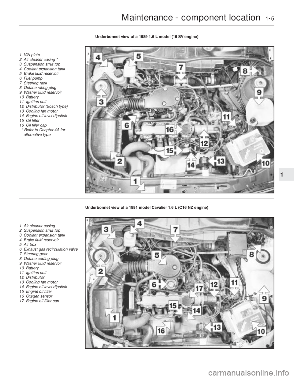
Maintenance - component location 1•5
1
Underbonnet view of a 1989 1.6 L model (16 SV engine)
1 VIN plate
2 Air cleaner casing *
3 Suspension strut top
4 Coolant expansion tank
5 Brake fluid reservoir
6 Fuel pump
7 Steering rack
8 Octane rating plug
9 Washer fluid reservoir
10 Battery
11 Ignition coil
12 Distributor (Bosch type)
13 Cooling fan motor
14 Engine oil level dipstick
15 Oil filter
16 Oil filler cap
* Refer to Chapter 4A for
alternative type
Underbonnet view of a 1991 model Cavalier 1.6 L (C16 NZ engine)
1 Air cleaner casing
2 Suspension strut top
3 Coolant expansion tank
4 Brake fluid reservoir
5 Air box
6 Exhaust gas recirculation valve
7 Steering gear
8 Octane coding plug
9 Washer fluid reservoir
10 Battery
11 Ignition coil
12 Distributor
13 Cooling fan motor
14 Engine oil level dipstick
15 Engine oil filter
16 Oxygen sensor
17 Engine oil filler cap
Page 177 of 525

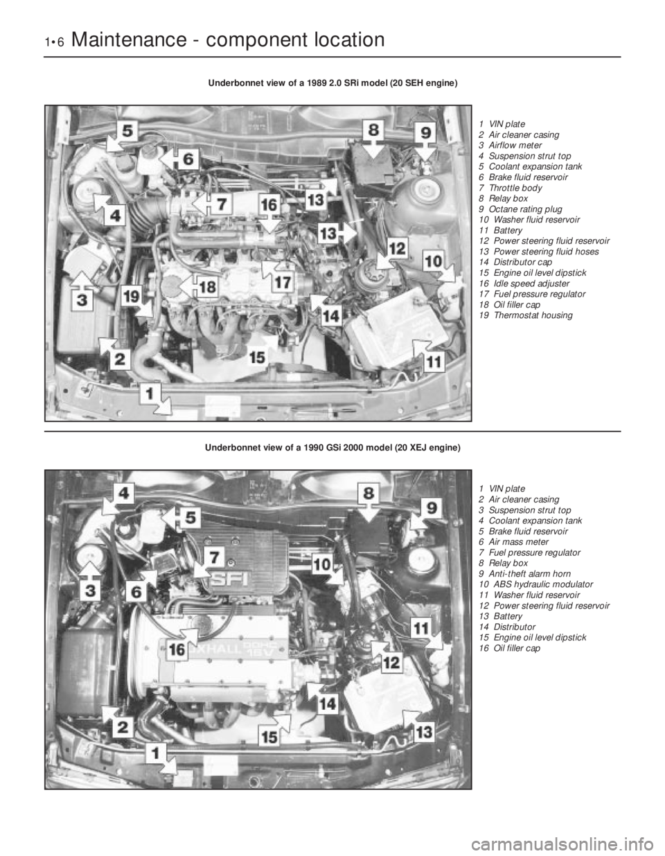
1•6Maintenance - component location
Underbonnet view of a 1989 2.0 SRi model (20 SEH engine)
1 VIN plate
2 Air cleaner casing
3 Airflow meter
4 Suspension strut top
5 Coolant expansion tank
6 Brake fluid reservoir
7 Throttle body
8 Relay box
9 Octane rating plug
10 Washer fluid reservoir
11 Battery
12 Power steering fluid reservoir
13 Power steering fluid hoses
14 Distributor cap
15 Engine oil level dipstick
16 Idle speed adjuster
17 Fuel pressure regulator
18 Oil filler cap
19 Thermostat housing
Underbonnet view of a 1990 GSi 2000 model (20 XEJ engine)
1 VIN plate
2 Air cleaner casing
3 Suspension strut top
4 Coolant expansion tank
5 Brake fluid reservoir
6 Air mass meter
7 Fuel pressure regulator
8 Relay box
9 Anti-theft alarm horn
10 ABS hydraulic modulator
11 Washer fluid reservoir
12 Power steering fluid reservoir
13 Battery
14 Distributor
15 Engine oil level dipstick
16 Oil filler cap