1988 OPEL CALIBRA low beam
[x] Cancel search: low beamPage 54 of 525
12•40Wiring diagrams
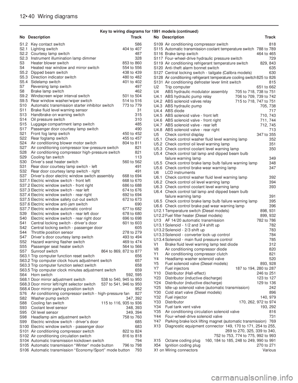
Key to wiring diagrams for 1991 models (continued)
NoDescriptionTrackNoDescriptionTrack
S1.2Key contact switch586
S2.1Lighting switch404 to 407
S2.2Courtesy lamp switch487
S2.3Instrument illumination lamp dimmer328
S3Heater blower switch853 to 860
S4Heated rear window and mirror switch554 to 556
S5.2Dipped beam switch438 to 439
S5.3Direction indicator switch480 to 482
S5.4Sidelamp switch401 to 402
S7Reversing lamp switch497
S8Brake lamp switch462
S9.2Windscreen wiper interval switch501 to 504
S9.5Rear window washer/wiper switch514 to 516
S10Automatic transmission starter inhibitor switch773 to 779
S11Brake fluid level warning sensor31
S13Handbrake-on warning switch315
S14Oil pressure switch310
S15Luggage compartment lamp switch485
S17Passenger door courtesy lamp switch490
S21Front fog lamp switch450 to 452
S22Rear foglamp switch455 to 457
S24Air conditioning blower motor switch804 to 811
S27Air conditioning compressor low-pressure switch821
S28Air conditioning compressor high-pressure switch821
S29Cooling fan switch113
S30Driver’s seat heater switch560 to 562
S31Rear door courtesy lamp switch - left491
S32Rear door courtesy lamp switch - right491
S37Driver’s door electric window switch assembly668 to 694
S37.1Electric window switch - front left668 to 670
S37.2Electric window switch - front right686 to 688
S37.3Electric window switch - rear left674 to 676
S37.4Electric window switch - rear right692 to 694
S37.5Electric window safety cut-out switch672 to 673
S37.6Electric window anti-jam switch690
S37.7Electric window automatic control677 to 682
S39Electric window switch - rear left door678 to 680
S40Electric window switch - rear right door696 to 698
S41Central locking switch - driver’s door601 to 603
S42Central locking switch - passenger door605
S44Throttle position sensor278 to 279
S47Driver’s door courtesy lamp switch493 to 494
S52Hazard warning flasher switch469 to 474
S55Passenger seat heater switch564 to 566
S57Sunroof switch864 to 869, 872 to 877
S63.1Trip computer function reset switch656
S63.2Trip computer clock hours adjustment switch657
S63.3Trip computer function select switch658
S63.5Trip computer clock minutes adjustment switch659
S64Horn switch592, 595
S68.1Door mirror adjustment switch538 to 540, 945 to 950
S68.3Door mirror left/right selector switch537 to 541, 946 to 950
S68.4Door mirror parking position switch952
S76Air conditioning compressor switch - high-pressure fan827
S82Washer pump switch347, 392
S88Cooling fan switch115 to 116, 935 to 936
S93Coolant level sensor348, 393
S95Oil level sensor349, 394
S98Headlamp aim adjustment switch758 to 760
S99Electric window switch - driver’s door685
S100Electric window switch - passenger door683
S101Air conditioning compressor switch822 to 824
S102Air conditioning circulation switch816 to 818
S104Automatic transmission kickdown switch794
S105Automatic transmission “Winter” mode button796 to 798
S106Automatic transmission “Economy/Sport” mode button793S109Air conditioning compressor switch818
S115Automatic transmission coolant temperature switch788 to 789
S116Brake lamp switch464 to 465
S117Four-wheel-drive hydraulic pressure switch729
S119Air conditioning refrigerant temperature switch829, 843
S120Anti-theft alarm bonnet switch635
S127Central locking switch - tailgate (Calibra models)630
S128Air conditioning refrigerant temperature cooling switch825 to 826
S131Air conditioning defroster lever limit switch815
U2Trip computer651 to 662
U4ABS hydraulic modulator assembly705 to 718, 738 to 751
U4.1ABS hydraulic pump relay706 to 709, 739 to 742
U4.2ABS solenoid valves relay715 to 718, 747 to 751
U4.3ABS hydraulic pump705, 738
U4.4ABS diode717
U4.5ABS solenoid valve - front left710, 743
U4.6ABS solenoid valve - front right711, 744
U4.7ABS solenoid valve - rear left712, 745
U4.8ABS solenoid valve - rear right713
U5Check control display347 to 355
U5.1Check control washer fluid level warning lamp352
U5.2Check control oil level warning lamp351
U5.3Check control coolant level warning lamp350
U5.4Check control tail lamp and dipped beam bulb
failure warning lamp349
U5.5Check control brake lamp bulb failure warning lamp348
U5.6Check control brake wear warning lamp347
U6LCD instruments
U6.1Check control washer fluid level warning lamp392
U6.2Check control oil level warning lamp394
U6.3Check control coolant level warning lamp393
U6.4Check control tail lamp and dipped beam bulb
failure warning lamp391
U6.5Check control brake lamp bulb failure warning lamp395
U6.6Check control brake pad wear warning lamp396
U12.1Temperature switch (Diesel models)898, 931
U12.2Fuel filter heater (Diesel models)899, 932
U13AF14/20automatic transmission782 to 786
U13.1Solenoid - 1/2 and 3/4 shift up782
U13.2Solenoid - 2/3 shift up783
U13.3Solenoid - converter lock-up control784
U13.4Solenoid - main fluid pressure control785
V1Brake fluid level warning lamp test diode312
V8Air conditioning compressor diode820
Y1Air conditioning compressor clutch821
Y4Headlamp washer solenoid valve520
Y5Fuel solenoid valve (Diesel models)893, 928
Y7Fuel injectors187 to 194, 280 to 287
Y10Distributor (Hall-effect)246 to 251
Y23Distributor (inductive discharge)123 to 127
Y24Distributor (inductive discharge)129 to 136
Y25Idle-up solenoid valve (automatic transmission)242
Y30Cold start valve (Diesel models)896
Y32Fuel injector140, 979
Y33Distributor170, 262, 972 to 974
Y34Fuel tank vent valve193, 292
Y35Air conditioning circulation solenoid valve816
Y44Four-wheel-drive solenoid valve731
Y47Parking brake lock lifting magnet (automatic transmission)769
X13Diagnostic equipment connector149, 170 to 171, 254 to 255,
269 to 270, 325, 339 to 340,
752 to 753, 774 to 775, 992 to 993
X15Octane coding plug160, 184 to 185, 248 to 249, 990 to 991
X54Ignition coding plug270 to 271
X1 onWiring connectorsVarious
Page 69 of 525

Wiring diagrams 12•55
12
Key to wiring diagrams for 1992 and later models
NoDescriptionTrackNoDescriptionTrack
E1Left parking lamp506
E2Left tail lamp507, 745
E3Licence plate lamp513
E4Right parking lamp509
E5Right tail lamp510, 746
E6Engine compartment lamp515
E7Left high beam 535
E8Right high beam536
E9Left low beam537, 747
E10Right low beam538, 748
E11Instrument lights728, 729
E12Selector lever lamp 498, 499
E13Boot lamp585
E14Passenger compartment lamp587
E15Glove box lamp677
E16Cigarette lighter lamp676
E17Left reversing lamp597
E18Right reversing lamp598
E19Heated back window652
E20Left fog lamp553
E21Right fog lamp554
E24Left rear fog lamp548
E25Left front heating mat660
E27Left rear reading lamp680, 681
E28Right rear reading lamp683, 684
E30Right front heating mat664
E32Clock lamp863
E37Left mirror make-up lamp686
E38Computer lamp854
E39Right rear foglamp549
E40Right mirror make-up lamp688
E41Passenger compartment delay lamp 588 to 590
E50Driver door lamp866
E51Passenger door lamp884
F1 onFusesVarious
F35Voltage stabilizer702
G1Battery101
G2Alternator114
G6Diesel alternator 402 to 405
H1Radio784 to 798
H3Turn signal lamp telltale716, 718
H4Oil pressure telltale710
H5Brake fluid telltale712
H6Telltale hazard warning system570
H7Charging indicator lamp710
H8High beam telltale722
H9Left stop lamp561, 749
H10Right stop lamp562, 750
H11Left front turn signal lamp572
H12Left rear turn signal lamp573
H13Right front turn signal lamp581
H14Right rear turn signal lamp582
H15Fuel telltale705, 706
H16Preheating time telltale715
H17Trailer turn signal lamp telltale717
H18Horn670
H19Headlamps on warning buzzer594, 595
H21Parking brake telltale713
H23Airbag telltale719
H25Heated back window & mirror telltale642, 765
H26ABS telltale721
H27Safety checking warning buzzer996 to 998
H28Seat belt warning telltale723
H30Engine telltale724H33Left auxiliary turn signal lamp576
H34Right auxiliary turn signal lamp578
H36Additional stop lamp563
H37Left front loudspeaker788 to 790
H38Right front loudspeaker794 to 796
H39Left rear loudspeaker788, 789
H40Right rear loudspeaker791, 792
H42Automatic program power telltale725
H45Four wheel drive telltale727
H46Catalytic converter temperature telltale729
H47Anti-theft warning unit horn838
H48Horn671
H51Traction control telltale720
H52Left front tweeter787 to 791
H53Right front tweeter793 to 797
K3Starter relay anti-theft warning unit109, 110
K5Fog lamps relay554 to 555
K6Air conditioning relay901, 902
K7Four stage air conditioning blower relay904, 905
K8Windshield wiper interval relay603 to 606
K9Headlamps washer unit relay619, 620
K10Flasher unit567 to 569
K20Ignition coil module149, 150, 171, 172, 241, 242, 302 to 305,
361 to 364, 1001 to 1005, 1055 to 1061
K22Coolant pump relay133, 134, 969, 970
K25Glow time relay440 to 443
K26Radiator blower relays972 to 974
K27Radiator blower relay137 to 139
K30Back window wiper interval relay613 to 615
K31Airbag control unit1191 to 1198
K34Radiator blower time delay relay356 to 358, 956 to 958
K35Heated back window & mirror time delay relay650 to 652
K37Central locking control unit805 to 812
K51Radiator blower relay430, 431, 942, 943, 956, 957
K52Radiator blower relay145 to 147, 433,435,
982 to 984, 960 to 962
K57Multec unit control211 to 230, 244 to 262
K58Fuel pump relay231, 232, 262, 263
K59Running light relay520 to 525
K60Compressor relay931,932
K61Motronic control unit270 to 294, 307 to 337,
366 to 396, 1007 to 1037, 1063 to 1096
K63Horn relay671, 672
K641 stage air conditioning blower relay913, 914
K67Radiator blower relay142, 143, 436, 437, 948,
949, 964, 965, 986, 987
K68Fuel injection unit relay295 to 299, 393 to 397,
334 to 338, 1093 to 1097, 1034 to 1038
K73High beam relay (Calibra)530, 531
K76Glow time control unit413 to 417
K77Glow plugs relay419, 420
K78Preresistor relay (70A)422, 423
K79Charge indicator relay406 to 408
K80Filter heating relay426, 427, 452, 453
K82Engine revolution relay447, 448
K83Four wheel drive unit control342 to 349
K84EZ Plus control unit155 to 166, 177 to 191
K85Automatic transmission control unit473 to 496
K86Check control unit736 to 752
K87Radiator blower relay945, 946, 953, 954, 977, 978
K88Catalytic converter temperature control unit462 to 464
K89Rear fog lamp relay543 to 545
K90Compressor relay (automatic transmission only)930, 931
K94Anti-theft warning unit control unit833 to 847
Page 70 of 525

12•56Wiring diagrams
Key to wiring diagrams for 1992 and later models (continued)
NoDescriptionTrackNoDescriptionTrack
K95Traction control control unit1125 to 1140
K97Headlamps washer pump time delay relay630 to 632
K101Parking position mirror relay774 to 777
K102Park brake shift lock control unit 469 to 471
L1Ignition coil150, 172, 205, 273, 241, 302, 361
L2Ignition coil1000 to 1004, 1054 to 1059
M1Starter105, 106
M2Windshield wiper motor601 to 604
M3Heating blower motor127 to 129
M4Radiator blower motor118, 120, 140, 356, 431, 948, 954, 980
M6Left headlamp wiper motor622 to 624
M7Right headlamp wiper motor 626 to 628
M8Back window wiper motor611 to 613
M10Air conditioning blower motor905 to 908
M11Radiator blower motor136, 434, 962, 984
M13Vectra/Cavalier sun roof motor1172 to 1175
M13.1Sun roof motor1172, 1174
M13.2Timing box microswitch1172
M13.3Timing box microswitch1174
M18Driver door central locking motor807 to 810
M19Left rear door central locking motor821 to 823
M20Right rear door central locking motor825 to 827
M21Fuel pump232, 263, 297, 339, 399, 834, 1098, 1039
M23Alternator blower motor135, 974
M24Headlamps washer pump632
M26Automatic antenna motor798 to 799
M30Driver side outside mirror638 to 641
M31Passenger side outside mirror644 to 647
M32Passenger door central locking motor813 to 816
M33Idle speed actuator285, 286, 317, 318, 381,
382, 1019, 1020, 1075, 1076
M37Tail gate/boot lid central locking motor818 to 821
M39Left headlamp levelling motor 692 to 695
M40Right headlamp levelling motor696 to 699
M41Fuel filler door central locking motor823, 824
M47Driver door window lifter motor867 to 871
M48Passenger door window lifter motor885 to 889
M49Left rear window lifter motor873 to 877
M50Right rear window lifter motor891 to 895
M55Windshield and back window washer pump617
M57Coolant pump134, 970
M60Calibra tailgate central locking motor827, 828
M61Calibra sun roof motor1178 to 1186
M61.1Sun roof motor1179 to 1182
M61.2Relay 11178, 1179
M61.3Relay 21184 to 1186
M62Driver side outside mirror760 to 767
M63Passenger side outside mirror769 to 776
M65TC throttle valve actuator1130 to 1134
M66Idle air stepper motor215 to 218, 250 to 253
P1Fuel indicator704
P2Coolant temperature indicator706
P3Clock862
P4Fuel sensor704
P5Coolant temperature sensor706
P7Tachometer708
P11Airflow meter 285 to 289
P12Coolant temperature sensor282, 381
P13Outside temperature sensor856
P14Distance sensor412, 413
P17Left front revolution sensor1110, 1154
P18Right front revolution sensor1113, 1157
P19Left rear revolution sensor1116, 1160
P20Right rear revolution sensor1119, 1163P21Distance sensor731
P23Intake manifold absolute pressure sensor160, 161, 185, 186,
217 to 219, 250 to 252
P24Engine oil temperature sensor162, 187
P27Left front brake lining sensor740
P28Right front brake lining sensor740
P29Intake manifold temperature sensor382, 1016, 1072
P30Coolant temperature sensor215, 248, 313, 1017, 1073
P32Heated exhaust oxygen sensor294, 295, 331, 332, 391,
392, 1034, 1035, 1093, 1094
P33Exhaust oxygen sensor229, 257
P34Throttle valve potentiometer221 to 223, 280, 281, 253 to 255,
383 to 385, 478, 479, 1018, 1019, 1074, 1075
P35Crankshaft impulse sensor178 to 180, 289 to 291, 248 to 250,
318 to 320, 373 to 375, 1025 to 1027, 1084 to 1086
P38Transmission oil temperature sensor494
P39Trailer bulb test sensor752 to 754
P43Electronic speedometer733
P44Air mass meter393 to 397, 334 to 338,
1037, 1038, 1096, 1097
P45Transmission input revolution sensor490, 491
P46Knock control sensor322, 323, 377, 378,
1022, 1023, 1078, 1079
P47Cylinder identification hall sensor325 to 327, 385 to 387,
1028 to 1030, 1087, 1089
P48Automatic transmission distance sensor488, 489
P50Catalytic converter temperature sensor463, 464
P53Driver side anti-theft warning unit sensor839 to 847
P54Passenger side anti-theft warning unit sensor839 to 847
P55Engine coolant temperature sensor415
P56Knock control sensor II1080, 1081
P57Antenna797
R3Cigarette lighter675
R5Glow plugs418 to 420, 441 to 443
R13Left heated washer nozzle 626
R14Right heated washer nozzle628
R19Radiator blower preresistor120, 140, 945
R22Glow plugs pre-resistor423
R23Driver airbag squib1194
S1Starter switch103 to 106
S1.2Key contact switch783
S2Light switch assy
S2.1Light switch504 to 507
S2.2Passenger compartment lamp switch587
S2.3Instrument lights dimmer728
S3Heating blower switch123 to 130
S4Heated back window & mirror switch654 to 657
S5Turn signal switch assy
S5.2Low beam switch536, 537
S5.3Turn signal switch580 to 582
S5.4Parking lamp switch501, 502
S7Back up lamp switch597, 599
S8Stop lamp switch562
S9Wiper unit switch
S9.2Interval windshield wiper switch601 to 604
S9.5Back window and washer unit wiper switch614 to 616
S10Automatic transmission switch472 to 478
S11Brake fluid control switch712
S13Parking brake switch713
S14Oil pressure switch710
S15Boot lamp switch585
S17Passenger door contact switch590
S20Pressure switch
S20.1Low pressure compressor switch925
Page 71 of 525
Wiring diagrams 12•57
12
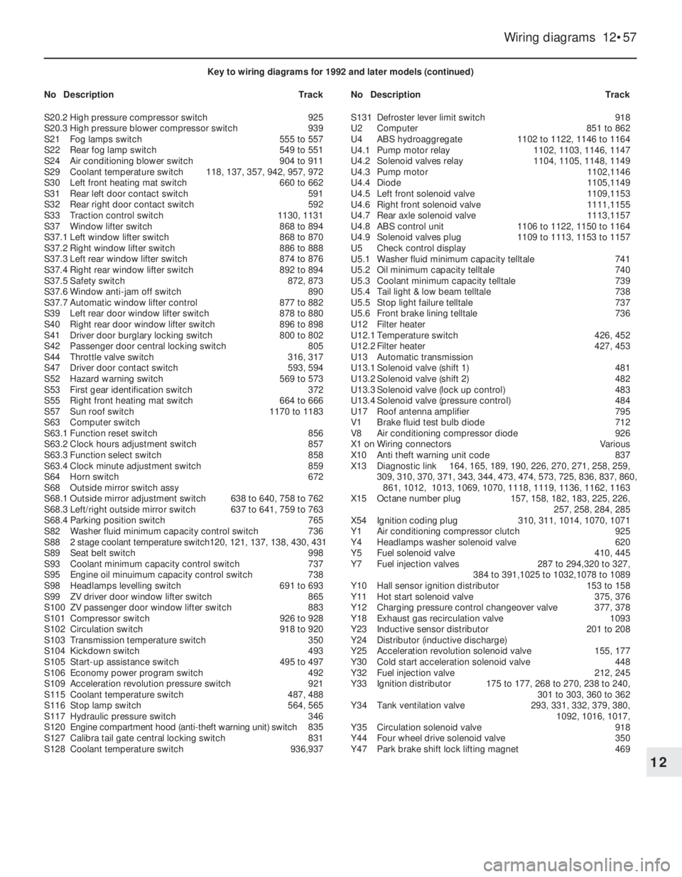
Key to wiring diagrams for 1992 and later models (continued)
NoDescriptionTrackNoDescriptionTrack
S20.2High pressure compressor switch925
S20.3High pressure blower compressor switch939
S21Fog lamps switch555 to 557
S22Rear fog lamp switch549 to 551
S24Air conditioning blower switch904 to 911
S29Coolant temperature switch118, 137, 357, 942, 957, 972
S30Left front heating mat switch660 to 662
S31Rear left door contact switch591
S32Rear right door contact switch592
S33Traction control switch1130, 1131
S37Window lifter switch868 to 894
S37.1Left window lifter switch868 to 870
S37.2Right window lifter switch886 to 888
S37.3Left rear window lifter switch874 to 876
S37.4Right rear window lifter switch892 to 894
S37.5Safety switch872, 873
S37.6Window anti-jam off switch890
S37.7Automatic window lifter control877 to 882
S39Left rear door window lifter switch878 to 880
S40Right rear door window lifter switch896 to 898
S41Driver door burglary locking switch800 to 802
S42Passenger door central locking switch805
S44Throttle valve switch316, 317
S47Driver door contact switch593, 594
S52Hazard warning switch569 to 573
S53First gear identification switch372
S55Right front heating mat switch664 to 666
S57Sun roof switch1170 to 1183
S63Computer switch
S63.1Function reset switch856
S63.2Clock hours adjustment switch857
S63.3Function select switch858
S63.4Clock minute adjustment switch859
S64Horn switch672
S68Outside mirror switch assy
S68.1Outside mirror adjustment switch638 to 640, 758 to 762
S68.3Left/right outside mirror switch637 to 641, 759 to 763
S68.4Parking position switch765
S82Washer fluid minimum capacity control switch736
S882 stage coolant temperature switch120, 121, 137, 138, 430, 431
S89Seat belt switch998
S93Coolant minimum capacity control switch737
S95Engine oil minuimum capacity control switch738
S98Headlamps levelling switch691 to 693
S99ZV driver door window lifter switch865
S100ZV passenger door window lifter switch883
S101Compressor switch926 to 928
S102Circulation switch918 to 920
S103Transmission temperature switch350
S104Kickdown switch493
S105Start-up assistance switch495 to 497
S106Economy power program switch492
S109Acceleration revolution pressure switch921
S115Coolant temperature switch487, 488
S116Stop lamp switch564, 565
S117Hydraulic pressure switch346
S120Engine compartment hood (anti-theft warning unit) switch835
S127Calibra tail gate central locking switch831
S128Coolant temperature switch936,937S131Defroster lever limit switch918
U2Computer851 to 862
U4ABS hydroaggregate1102 to 1122, 1146 to 1164
U4.1Pump motor relay1102, 1103, 1146, 1147
U4.2Solenoid valves relay1104, 1105, 1148, 1149
U4.3Pump motor1102,1146
U4.4Diode1105,1149
U4.5Left front solenoid valve1109,1153
U4.6Right front solenoid valve1111,1155
U4.7Rear axle solenoid valve1113,1157
U4.8ABS control unit1106 to 1122, 1150 to 1164
U4.9Solenoid valves plug1109 to 1113, 1153 to 1157
U5Check control display
U5.1Washer fluid minimum capacity telltale741
U5.2Oil minimum capacity telltale740
U5.3Coolant minimum capacity telltale739
U5.4Tail light & low beam telltale738
U5.5Stop light failure telltale737
U5.6Front brake lining telltale736
U12Filter heater
U12.1Temperature switch426, 452
U12.2Filter heater427, 453
U13Automatic transmission
U13.1Solenoid valve (shift 1)481
U13.2Solenoid valve (shift 2)482
U13.3Solenoid valve (lock up control)483
U13.4Solenoid valve (pressure control)484
U17Roof antenna amplifier795
V1Brake fluid test bulb diode712
V8Air conditioning compressor diode926
X1 onWiring connectorsVarious
X10Anti theft warning unit code837
X13Diagnostic link164, 165, 189, 190, 226, 270, 271, 258, 259,
309, 310, 370, 371, 343, 344, 473, 474, 573, 725, 836, 837, 860,
861, 1012, 1013, 1069, 1070, 1118, 1119, 1136, 1162, 1163
X15Octane number plug157, 158, 182, 183, 225, 226,
257, 258, 284, 285
X54Ignition coding plug310, 311, 1014, 1070, 1071
Y1Air conditioning compressor clutch925
Y4Headlamps washer solenoid valve620
Y5Fuel solenoid valve410, 445
Y7Fuel injection valves287 to 294,320 to 327,
384 to 391,1025 to 1032,1078 to 1089
Y10Hall sensor ignition distributor153 to 158
Y11Hot start solenoid valve375, 376
Y12Charging pressure control changeover valve377, 378
Y18Exhaust gas recirculation valve1093
Y23Inductive sensor distributor201 to 208
Y24Distributor (inductive discharge)
Y25Acceleration revolution solenoid valve155, 177
Y30Cold start acceleration solenoid valve 448
Y32Fuel injection valve212, 245
Y33Ignition distributor175 to 177, 268 to 270, 238 to 240,
301 to 303, 360 to 362
Y34Tank ventilation valve293, 331, 332, 379, 380,
1092, 1016, 1017,
Y35Circulation solenoid valve918
Y44Four wheel drive solenoid valve350
Y47Park brake shift lock lifting magnet469
Page 149 of 525
8Disconnect the battery negative lead.
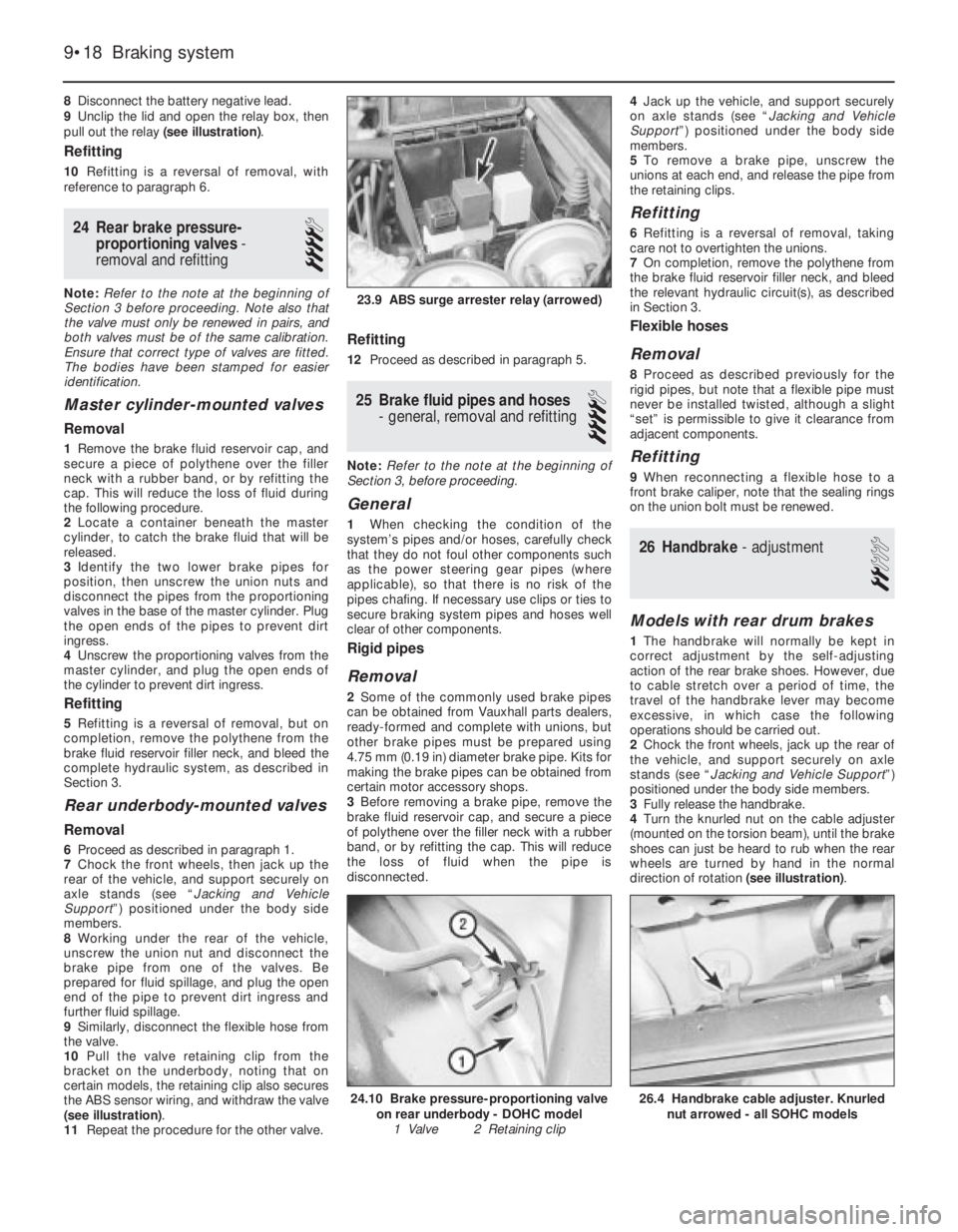
9Unclip the lid and open the relay box, then
pull out the relay (see illustration).
Refitting
10Refitting is a reversal of removal, with
reference to paragraph 6.
24Rear brake pressure-
proportioning valves -
removal and refitting
4
Note: Refer to the note at the beginning of
Section 3 before proceeding. Note also that
the valve must only be renewed in pairs, and
both valves must be of the same calibration.
Ensure that correct type of valves are fitted.
The bodies have been stamped for easier
identification.
Master cylinder-mounted valves
Removal
1Remove the brake fluid reservoir cap, and
secure a piece of polythene over the filler
neck with a rubber band, or by refitting the
cap. This will reduce the loss of fluid during
the following procedure.
2Locate a container beneath the master
cylinder, to catch the brake fluid that will be
released.
3Identify the two lower brake pipes for
position, then unscrew the union nuts and
disconnect the pipes from the proportioning
valves in the base of the master cylinder. Plug
the open ends of the pipes to prevent dirt
ingress.
4Unscrew the proportioning valves from the
master cylinder, and plug the open ends of
the cylinder to prevent dirt ingress.
Refitting
5Refitting is a reversal of removal, but on
completion, remove the polythene from the
brake fluid reservoir filler neck, and bleed the
complete hydraulic system, as described in
Section 3.
Rear underbody-mounted valves
Removal
6Proceed as described in paragraph 1.
7Chock the front wheels, then jack up the
rear of the vehicle, and support securely on
axle stands (see “Jacking and Vehicle
Support”) positioned under the body side
members.
8Working under the rear of the vehicle,
unscrew the union nut and disconnect the
brake pipe from one of the valves. Be
prepared for fluid spillage, and plug the open
end of the pipe to prevent dirt ingress and
further fluid spillage.
9Similarly, disconnect the flexible hose from
the valve.
10Pull the valve retaining clip from the
bracket on the underbody, noting that on
certain models, the retaining clip also secures
the ABS sensor wiring, and withdraw the valve
(see illustration).
11Repeat the procedure for the other valve.
Refitting
12Proceed as described in paragraph 5.
25Brake fluid pipes and hoses
- general, removal and refitting
4
Note: Refer to the note at the beginning of
Section 3, before proceeding.
General
1When checking the condition of the
system’s pipes and/or hoses, carefully check
that they do not foul other components such
as the power steering gear pipes (where
applicable), so that there is no risk of the
pipes chafing. If necessary use clips or ties to
secure braking system pipes and hoses well
clear of other components.
Rigid pipes
Removal
2Some of the commonly used brake pipes
can be obtained from Vauxhall parts dealers,
ready-formed and complete with unions, but
other brake pipes must be prepared using
4.75 mm (0.19 in) diameter brake pipe. Kits for
making the brake pipes can be obtained from
certain motor accessory shops.
3Before removing a brake pipe, remove the
brake fluid reservoir cap, and secure a piece
of polythene over the filler neck with a rubber
band, or by refitting the cap. This will reduce
the loss of fluid when the pipe is
disconnected.4Jack up the vehicle, and support securely
on axle stands (see “Jacking and Vehicle
Support”) positioned under the body side
members.
5To remove a brake pipe, unscrew the
unions at each end, and release the pipe from
the retaining clips.
Refitting
6Refitting is a reversal of removal, taking
care not to overtighten the unions.
7On completion, remove the polythene from
the brake fluid reservoir filler neck, and bleed
the relevant hydraulic circuit(s), as described
in Section 3.
Flexible hoses
Removal
8Proceed as described previously for the
rigid pipes, but note that a flexible pipe must
never be installed twisted, although a slight
“set” is permissible to give it clearance from
adjacent components.
Refitting
9When reconnecting a flexible hose to a
front brake caliper, note that the sealing rings
on the union bolt must be renewed.
26Handbrake - adjustment
2
Models with rear drum brakes
1The handbrake will normally be kept in
correct adjustment by the self-adjusting
action of the rear brake shoes. However, due
to cable stretch over a period of time, the
travel of the handbrake lever may become
excessive, in which case the following
operations should be carried out.
2Chock the front wheels, jack up the rear of
the vehicle, and support securely on axle
stands (see “Jacking and Vehicle Support”)
positioned under the body side members.
3Fully release the handbrake.
4Turn the knurled nut on the cable adjuster
(mounted on the torsion beam), until the brake
shoes can just be heard to rub when the rear
wheels are turned by hand in the normal
direction of rotation (see illustration).
9•18Braking system
23.9 ABS surge arrester relay (arrowed)
26.4 Handbrake cable adjuster. Knurled
nut arrowed - all SOHC models24.10 Brake pressure-proportioning valve
on rear underbody - DOHC model
1 Valve 2 Retaining clip
Page 150 of 525
5Loosen the adjuster nut until the wheels are
just free to turn.
6The handbrake must start to operate with
the lever on the second notch of the ratchet.
7On completion of adjustment, check the
handbrake cables for free movement, and
apply a little grease to the adjuster threads to
prevent corrosion.
8Lower the vehicle to the ground.
Models with rear disc brakes
9Where applicable, remove the wheel trims,
then loosen the rear roadwheel bolts and
chock the front wheels. Jack up the rear of the
vehicle, and support securely on axle stands
(see “Jacking and Vehicle Support”)
positioned under the body side members.
Remove the roadwheels.
10Pull the handbrake lever as far as the
second notch on the ratchet.
11On DOHC models fitted with a catalytic
converter, unscrew the four securing nuts and
withdraw the exhaust centre box heat shield
by carefully sliding it round the centre box.
12On all SOHC models, loosen the knurled
nut on the cable adjuster (mounted on the
torsion beam).
13On DOHC models, loosen the nut
securing the cable equaliser yoke to the
handbrake lever operating rod.
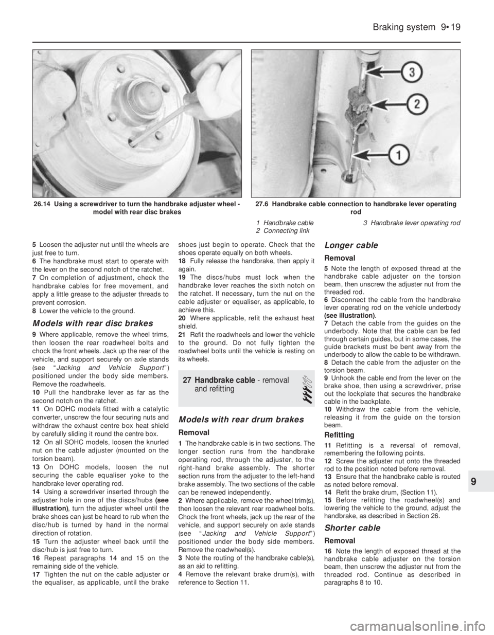
14Using a screwdriver inserted through the
adjuster hole in one of the discs/hubs (see
illustration), turn the adjuster wheel until the
brake shoes can just be heard to rub when the
disc/hub is turned by hand in the normal
direction of rotation.
15Turn the adjuster wheel back until the
disc/hub is just free to turn.
16Repeat paragraphs 14 and 15 on the
remaining side of the vehicle.
17Tighten the nut on the cable adjuster or
the equaliser, as applicable, until the brakeshoes just begin to operate. Check that the
shoes operate equally on both wheels.
18Fully release the handbrake, then apply it
again.
19The discs/hubs must lock when the
handbrake lever reaches the sixth notch on
the ratchet. If necessary, turn the nut on the
cable adjuster or equaliser, as applicable, to
achieve this.
20Where applicable, refit the exhaust heat
shield.
21Refit the roadwheels and lower the vehicle
to the ground. Do not fully tighten the
roadwheel bolts until the vehicle is resting on
its wheels.
27Handbrake cable - removal
and refitting
3
Models with rear drum brakes
Removal
1The handbrake cable is in two sections. The
longer section runs from the handbrake
operating rod, through the adjuster, to the
right-hand brake assembly. The shorter
section runs from the adjuster to the left-hand
brake assembly. The two sections of the cable
can be renewed independently.
2Where applicable, remove the wheel trim(s),
then loosen the relevant rear roadwheel bolts.
Chock the front wheels, jack up the rear of the
vehicle, and support securely on axle stands
(see “Jacking and Vehicle Support”)
positioned under the body side members.
Remove the roadwheel(s).
3Note the routing of the handbrake cable(s),
as an aid to refitting.
4Remove the relevant brake drum(s), with
reference to Section 11.
Longer cable
Removal
5Note the length of exposed thread at the
handbrake cable adjuster on the torsion
beam, then unscrew the adjuster nut from the
threaded rod.
6Disconnect the cable from the handbrake
lever operating rod on the vehicle underbody
(see illustration).
7Detach the cable from the guides on the
underbody. Note that the cable can be fed
through certain guides, but in some cases, the
guide brackets must be bent away from the
underbody to allow the cable to be withdrawn.
8Detach the cable from the adjuster on the
torsion beam.
9Unhook the cable end from the lever on the
brake shoe, then using a screwdriver, prise
out the lockplate that secures the handbrake
cable in the backplate.
10Withdraw the cable from the vehicle,
releasing it from the guide on the torsion
beam.
Refitting
11Refitting is a reversal of removal,
remembering the following points.
12Screw the adjuster nut onto the threaded
rod to the position noted before removal.
13Ensure that the handbrake cable is routed
as noted before removal.
14Refit the brake drum, (Section 11).
15Before refitting the roadwheel(s) and
lowering the vehicle to the ground, adjust the
handbrake, as described in Section 26.
Shorter cable
Removal
16Note the length of exposed thread at the
handbrake cable adjuster on the torsion
beam, then unscrew the adjuster nut from the
threaded rod. Continue as described in
paragraphs 8 to 10.
Braking system 9•19
27.6 Handbrake cable connection to handbrake lever operating
rod
1 Handbrake cable
2 Connecting link3 Handbrake lever operating rod26.14 Using a screwdriver to turn the handbrake adjuster wheel -
model with rear disc brakes
9
Page 151 of 525
Refitting
17Proceed as described in paragraphs 11
to 15 inclusive.
Models with rear disc brakes
(SOHC)
General
18The procedure is as described for models
with rear drum brakes, remembering the
following points.
19Ignore the references to removal and
refitting of the brake drum.
20Note that there is no lockplate securing
the handbrake cable to the brake backplate,
but the return spring must be unhooked from
the cable end.
21On models with a catalytic converter,
when removing the longer cable, unscrew the
four securing nuts and withdraw the exhaust
centre box heat shield by carefully sliding it
round the centre box.
DOHC models
Removal
22The left and right-hand handbrake cables,
and the equaliser yoke, are removed as an
assembly on DOHC models.
23Loosen the rear roadwheel bolts, then
chock the front wheels, jack up the rear of the
vehicle, and support securely on axle stands
(see “Jacking and Vehicle Support”)
positioned under the body side members.
Remove the roadwheels.
24Note the routing of the handbrake cables,
as an aid to refitting.
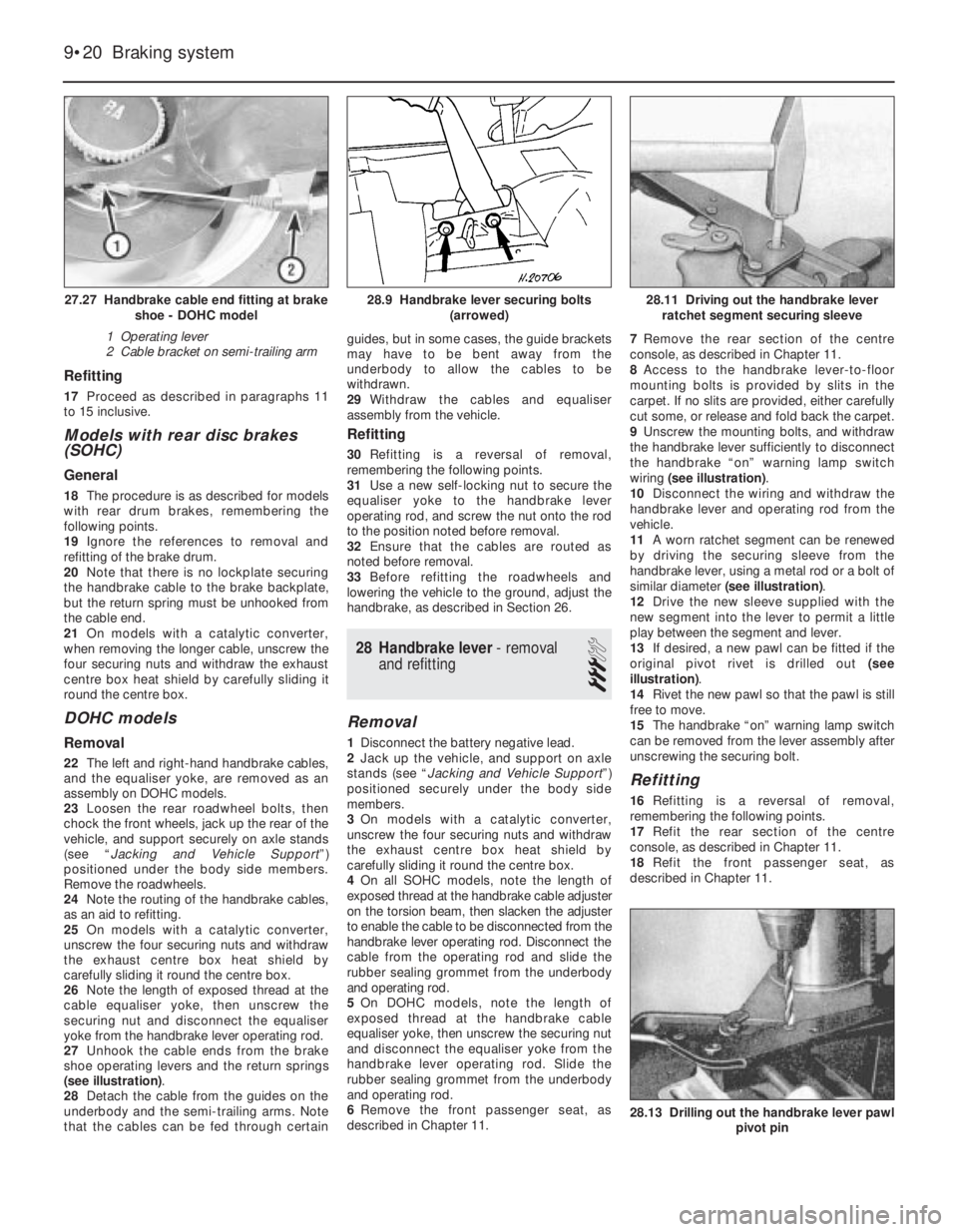
25On models with a catalytic converter,
unscrew the four securing nuts and withdraw
the exhaust centre box heat shield by
carefully sliding it round the centre box.
26Note the length of exposed thread at the
cable equaliser yoke, then unscrew the
securing nut and disconnect the equaliser
yoke from the handbrake lever operating rod.
27Unhook the cable ends from the brake
shoe operating levers and the return springs
(see illustration).
28Detach the cable from the guides on the
underbody and the semi-trailing arms. Note
that the cables can be fed through certainguides, but in some cases, the guide brackets
may have to be bent away from the
underbody to allow the cables to be
withdrawn.
29Withdraw the cables and equaliser
assembly from the vehicle.
Refitting
30Refitting is a reversal of removal,
remembering the following points.
31Use a new self-locking nut to secure the
equaliser yoke to the handbrake lever
operating rod, and screw the nut onto the rod
to the position noted before removal.
32Ensure that the cables are routed as
noted before removal.
33Before refitting the roadwheels and
lowering the vehicle to the ground, adjust the
handbrake, as described in Section 26.
28Handbrake lever - removal
and refitting
3
Removal
1Disconnect the battery negative lead.
2Jack up the vehicle, and support on axle
stands (see “Jacking and Vehicle Support”)
positioned securely under the body side
members.
3On models with a catalytic converter,
unscrew the four securing nuts and withdraw
the exhaust centre box heat shield by
carefully sliding it round the centre box.
4On all SOHC models, note the length of
exposed thread at the handbrake cable adjuster
on the torsion beam, then slacken the adjuster
to enable the cable to be disconnected from the
handbrake lever operating rod. Disconnect the
cable from the operating rod and slide the
rubber sealing grommet from the underbody
and operating rod.
5On DOHC models, note the length of
exposed thread at the handbrake cable
equaliser yoke, then unscrew the securing nut
and disconnect the equaliser yoke from the
handbrake lever operating rod. Slide the
rubber sealing grommet from the underbody
and operating rod.
6Remove the front passenger seat, as
described in Chapter 11.7Remove the rear section of the centre
console, as described in Chapter 11.
8Access to the handbrake lever-to-floor
mounting bolts is provided by slits in the
carpet. If no slits are provided, either carefully
cut some, or release and fold back the carpet.
9Unscrew the mounting bolts, and withdraw
the handbrake lever sufficiently to disconnect
the handbrake “on” warning lamp switch
wiring (see illustration).
10Disconnect the wiring and withdraw the
handbrake lever and operating rod from the
vehicle.
11A worn ratchet segment can be renewed
by driving the securing sleeve from the
handbrake lever, using a metal rod or a bolt of
similar diameter (see illustration).
12Drive the new sleeve supplied with the
new segment into the lever to permit a little
play between the segment and lever.
13If desired, a new pawl can be fitted if the
original pivot rivet is drilled out (see
illustration).
14Rivet the new pawl so that the pawl is still
free to move.
15The handbrake “on” warning lamp switch
can be removed from the lever assembly after
unscrewing the securing bolt.
Refitting
16Refitting is a reversal of removal,
remembering the following points.
17Refit the rear section of the centre
console, as described in Chapter 11.
18Refit the front passenger seat, as
described in Chapter 11.
9•20Braking system
28.13 Drilling out the handbrake lever pawl
pivot pin
28.11 Driving out the handbrake lever
ratchet segment securing sleeve28.9 Handbrake lever securing bolts
(arrowed)27.27 Handbrake cable end fitting at brake
shoe - DOHC model
1 Operating lever
2 Cable bracket on semi-trailing arm
Page 178 of 525
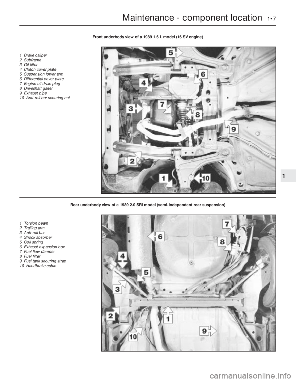
Maintenance - component location 1•7
1
Front underbody view of a 1989 1.6 L model (16 SV engine)
1 Brake caliper
2 Subframe
3 Oil filter
4 Clutch cover plate
5 Suspension lower arm
6 Differential cover plate
7 Engine oil drain plug
8 Driveshaft gaiter
9 Exhaust pipe
10 Anti-roll bar securing nut
Rear underbody view of a 1989 2.0 SRi model (semi-independent rear suspension)
1 Torsion beam
2 Trailing arm
3 Anti-roll bar
4 Shock absorber
5 Coil spring
6 Exhaust expansion box
7 Fuel flow damper
8 Fuel filter
9 Fuel tank securing strap
10 Handbrake cable