1988 FIAT TEMPRA length
[x] Cancel search: lengthPage 137 of 171

Job 15. Flexible hoses -
replacement.
• Step 8: Bleed the brakes, see Job
17
H INSIDE INFORMATION: When disconnecting brake
pipes or hoses, it is helpful to minimise brake fluid loss.
This can be done by unscrewing the master cylinder
reservoir cap, laying a sheet of plastic across the
opening, and refitting the cap. This will prevent atmos-
pheric pressure from pushing the fluid out of opened
lines. D
/ • If a rigid pipe starts to
twist with the union, grip
the pipe as lightly as
possible, and see if you can stop it from turning.
• If not, cut through the pipe with a junior hacksaw
and replace the length of rigid pipe.
Job 16. Metal pipes -
replacement.
B INSIDE INFORMATION: When disconnecting brake
pipes or hoses, it is helpful to minimise brake fluid loss.
This can be done by unscrewing the master cylinder
reservoir cap, laying a sheet of plastic across the
opening, and refitting the cap. This will prevent atmos-
pheric pressure from pushing the fluid out of opened
lines. A pipe spanner makes the job much easier! B
Step 1: Undo the unions at each end of a pipe length.
Patience is often required because of the union seizing both in
its threads and on the pipe. See MAKING IT EASY! after Job
15,
Step 8 Use penetrating oil to help free seized unions, and
use a split-ring spanner rather than an open-ended one, to
reduce the risk of rounding off the union nuts.
• Step 2: Detach the pipe length from its securing clips and
remove it.
i^vj ens s * ^ step 3: where possible, use the old pipe as
a pattern to shape the new
one prior to fitting.
• Step 4: Follow the original route and secure the pipe in
the body clips.
Q Step 5: Connect the unions and bleed the system. See
Job
17
Job 17. Brake bleeding.
B INSIDE INFORMATION: Unless the master cylinder or
pressure regulating valve has been disturbed, it will only
be necessary to bleed the end of the braking system
which has been opened. If bleeding the whole system,
start bleeding at the left-hand rear brake. B
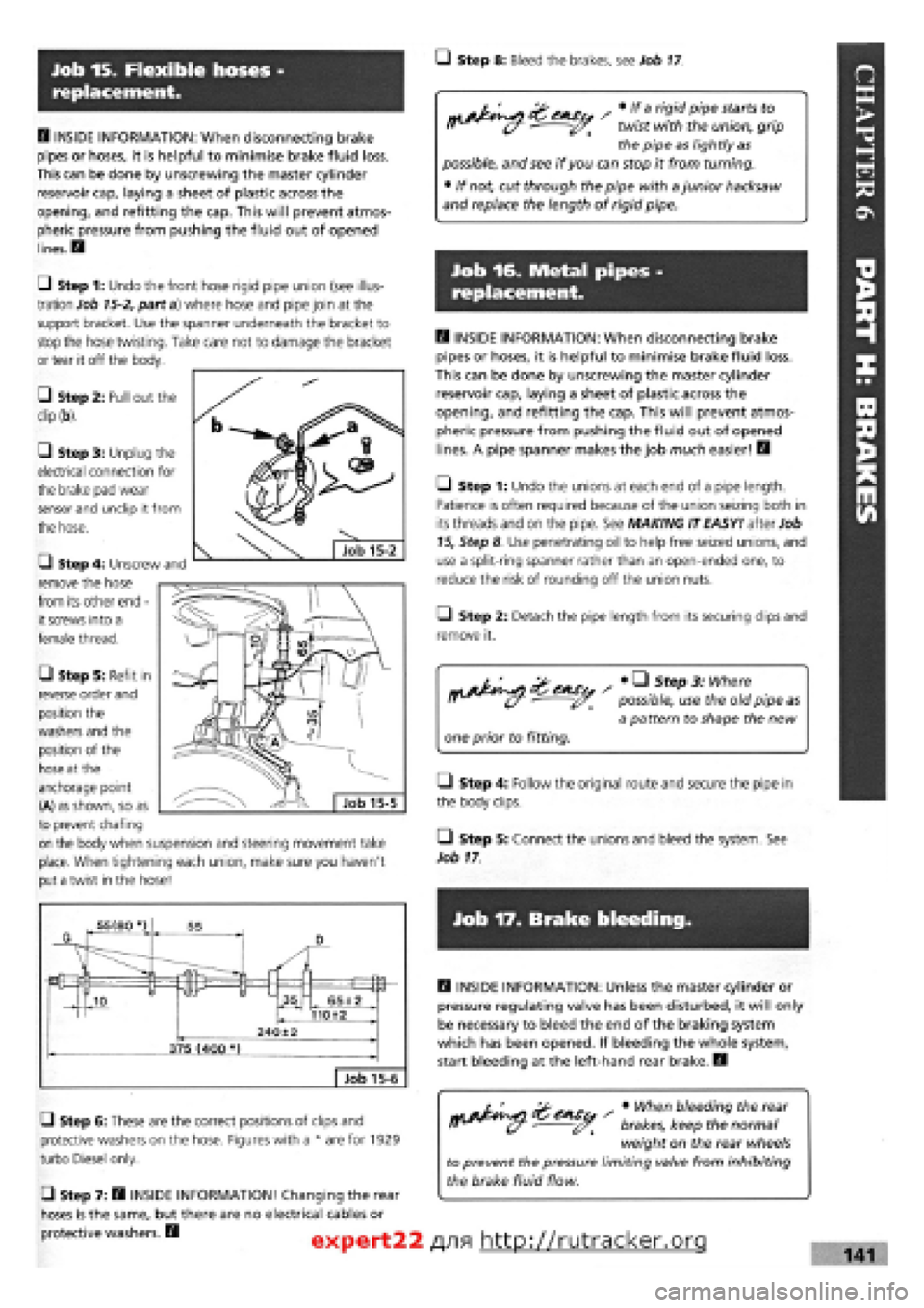
G Step 6: These are the correct positions of clips and
protective washers on the hose. Figures with a * are for 1929
turbo Diesel only.
• Step 7: B INSIDE INFORMATION! Changing the rear
hoses is the same, but there are no electrical cables or
protective washers. B
s • When bleeding the rear
brakes, keep the normal
weight on the rear wheels
to prevent the pressure limiting valve from inhibiting
the brake fluid flow.
expert22 f
\9\ http://rutracker.org 141
Ul Step 1: Undo the front hose rigid pipe union (see illus-
tration Job
15-2,
part a) where hose and pipe join at the
support bracket. Use the spanner underneath the bracket to
stop the hose twisting. Take care not to damage the bracket
or tear it off the body.
• Step 2: Pull out the
dip (b).
G Step 3: Unplug the
electrical connection for
the brake pad wear
sensor and unclip it from
the hose.
G Step 4: Unscrew and
remove the hose
from its other end -
it screws into a
female thread.
• Step 5: Refit in
reverse order and
position the
washers and the
position of the
hose at the
anchorage point
(A) as shown, so as
to prevent chafing
on the body when suspension and steering movement take
place. When tightening each union, make sure you haven't
put a twist in the hose!
Page 138 of 171

• Step 1:
Push a tight
fitting length
of plastic or
rubber tubing
(a) onto the
first bleed
screw (b) and
immerse the
other end in a
small quantity
of brake fluid
(c) contained in a glass jar in such a way that no air can
accidentally be pulled up the tube.
• Step 2: With a ring spanner (illustrations Job 17-1, part,
d), undo the brake bleed screw (at the drum brake backplate
or on the disc caliper body) by half a turn. Have your helper
push the brake pedal to the floor and hold it there while you
lock up the bleed valve. Then release the pedal slowly. Repeat
several times, with the following suggested dialogue:
YOU. (Open bleed screw) "Open!"
(called
out
loud)
HELPER.
(Pushes
pedal down) "Down!"
YOU.
(Close
bleed screw) "Closed!"
HELPER. (Letspedal up) "Up!"
-
repeated, as necessary.
IMPORTANT NOTE: Take great care not to let the master
cylinder run out of brake fluid. Otherwise you will
introduce fresh air into the system and have to start
again. Use ONLY fresh brake fluid from a previously
unopened container.
• Step 3: Top up the fluid reservoir frequently while
repeating the bleeding operation until all air is expelled from
the brake line (no bubbles appear in the tube or jar).
LI Step 4: Bleed each remaining brake in the same way,
going to the right-hand front next, followed by the right-hand
rear, and finishing with the left-hand front brake. Top up fluid
and check all connections for leaks.
Job 18. Handbrake cables -
replacement.
• Step 1: Familiarise yourself with the handbrake cable
layout. The following instructions refer to this drawing.
FRONT CABLE
Q Step 2: Jack up and support the rear of the car on axle
stands.
LI Step 3: From inside the car, remove the handbrake lever
cover by undoing the single fixing screw and fully release the
handbrake.
D Step 4: Unscrew the adjusting nut from the end of the
cable. You will find it underneath the base of the handbrake
lever.
• Step 5: From under the car, release the front ends of the
rear cables from the equaliser, then pull the front cable
through the floor aperture.
LI Step 6: Refit in the reverse order and adjust the cable nut
until the lever travels no more than three notches on the
ratchet when you pull the brake on, and when released, the
wheels still revolve freely.
REAR CABLES
• Step 7: Carry out Steps 1 to 3.
• Step 8: Unscrew the adjusting nut to the end of its
thread.
• Step 9: Unhook the front of the rear cables from the
equaliser. See Step 5
• Step 10: In the case of rear drum brakes, detach the
cables from the brakes as described in Job 5, Steps 3 and
4.
LI Step 11: In the case of disc rear brakes, see Job 8, Step
1.
• Step 12: Re-assemble in reverse order.
1 - handbrake lever and toothed sector 2 - front cable and anchorage 3 - rear cables 4 - support plate
5 - equaliser 6 - adjusting nut 7 - cable mounting bracket 8 - handbrake lever cover
Job 18-1
• Step 13: Adjust the handbrake
cable until the lever comes up no more
than three notches and when released,
allows both of the rear wheels to revolve
freely. Try spinning them by hand with
rear of the car raised off the ground.
Page 140 of 171

Job 3. Radiator grille - removal
and refitting.
Job 5. Tipo tailgate locking
mechanism - removal and
refitting.
Job 4. Tipo/Tempra tailgate -
removal and refitting.
Q Step 5: Undo the securing bolts (see illustration Job
2-1,
part
10)
and remove the lock.
Q Step 6: Refit in reverse order.
Q Step 7: Replace a cable by disconnecting it at each end
and releasing it from any securing clips. Run the new cable
along the same route and re-connect and secure.
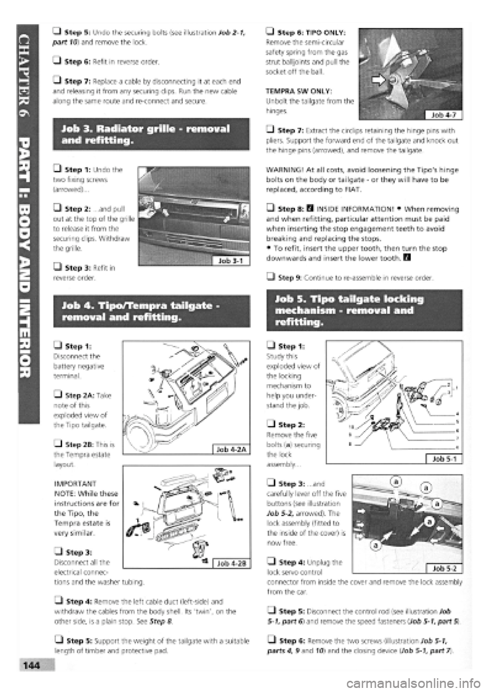
• Step 1: Undo the
two fixing screws
(arrowed)...
Q Step 2: ...and pull
out at the top of the grille
to release it from the
securing clips. Withdraw
the grille.
• Step 3: Refit in
reverse order.
• Step 1:
Disconnect the
battery negative
terminal.
• Step 2A: Take
note of this
exploded view of
the Tipo tailgate.
• Step 2B: This is
the Tempra estate
layout.
IMPORTANT
NOTE: While these
instructions are for
the Tipo, the
Tempra estate is
very similar.
• Step 1:
Study this
exploded view of
the locking
mechanism to
help you under-
stand the job.
• Step 2:
Remove the five
bolts (a) securing
the lock
assembly...
• Step 3: ...and
carefully lever off the five
buttons (see illustration
Job
5-2,
arrowed). The
lock assembly (fitted to
the inside of the cover) is
now free.
• Step 6: TIPO ONLY:
Remove the semi-circular
safety spring from the gas
strut balljoints and pull the
socket off the ball.
TEMPRA SW ONLY:
Unbolt the tailgate from the
hinges.
• Step 7: Extract the circlips retaining the hinge pins with
pliers. Support the forward end of the tailgate and knock out
the hinge pins (arrowed), and remove the tailgate.
WARNING! At all costs, avoid loosening the Tipo's hinge
bolts on the body or tailgate
-
or they will have to be
replaced, according to FIAT.
• Step 8: H INSIDE INFORMATION! • When removing
and when refitting, particular attention must be paid
when inserting the stop engagement teeth to avoid
breaking and replacing the stops.
• To refit, insert the upper tooth, then turn the stop
downwards and insert the lower tooth. B
Q Step 9: Continue to re-assemble in reverse order.
Job 5-1
• Step 3:
Disconnect all the
electrical connec-
tions and the washer tubing.
• Step 4: Remove the left cable duct (left-side) and
withdraw the cables from the body shell. Its 'twin', on the
other side, is a plain stop. See Step 8
• Step 4: Unplug the
lock servo control
connector from inside the cover and remove the lock assembly
from the car.
Q Step 5: Disconnect the control rod (see illustration Job
5-1,
part 6) and remove the speed fasteners (Job
5-1,
part
5).
• Step 5: Support the weight of the tailgate with a suitable
length of timber and protective pad.
• Step 6: Remove the two screws (illustration Job
5-1,
parts 4, 9 and
10)
and the closing device (Job
5-1,
part
7).