Page 216 of 648

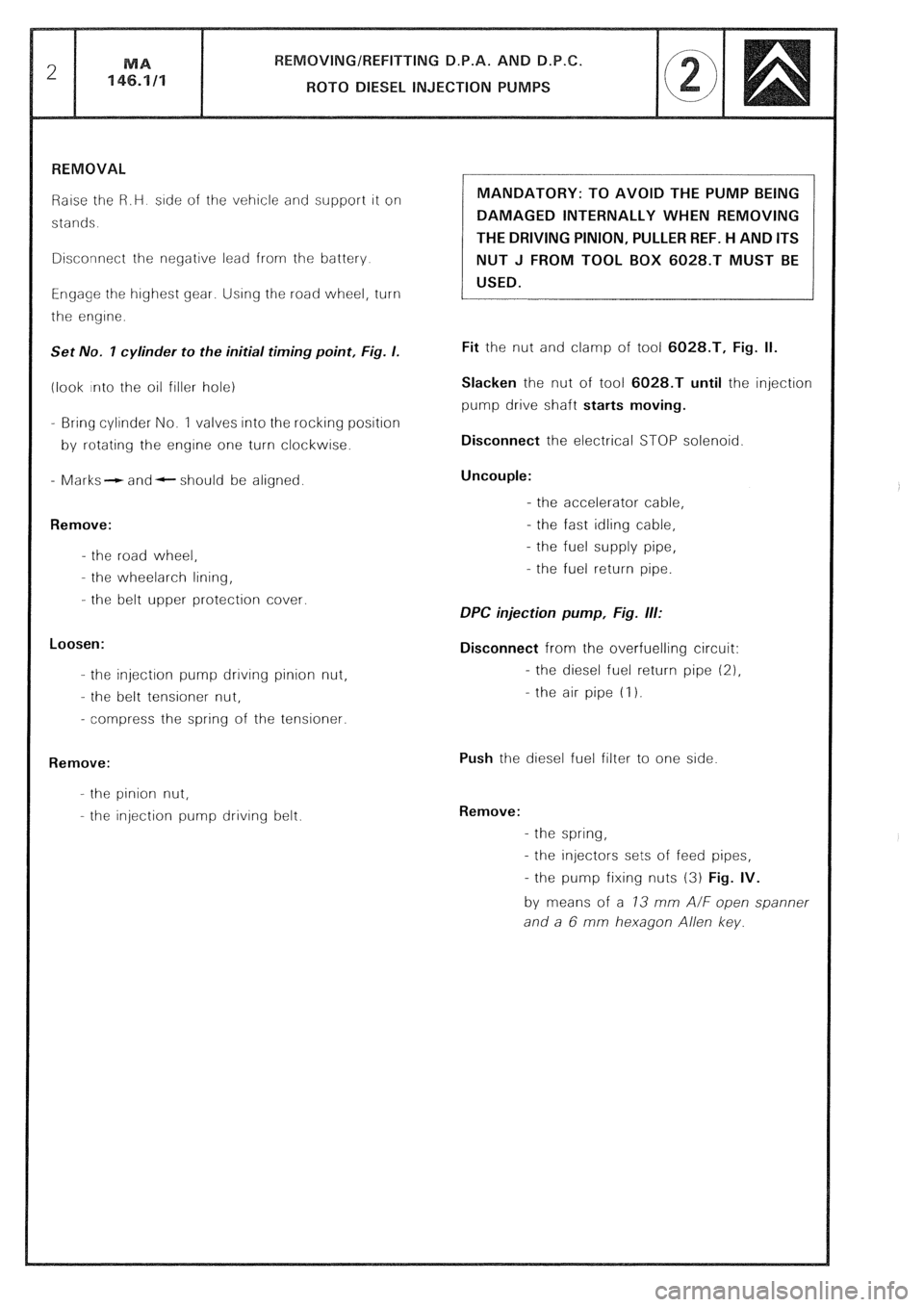
Raise the R.H side of the vehicle and support it on
stands.
Disconnect the negative lead from the battery
Engage the highest gear. Using the road wheel, turn
the engine.
Set No. I cylinder to the initial timing point, Fig. I.
(look into the oil filler hole)
- Bring cylinder No. 1 valves into the rocking position
by rotating the engine one turn clockwise.
- Marks- and- should be aligned.
Remove:
- the road wheel,
- the wheelarch lining,
- the belt upper protection cover.
Loosen:
- the injection pump drrvrng pinion nut,
- the belt tensioner nut,
- compress the spring of the tensioner.
Remove:
- the pinion nut,
- the injection pump driving belt. MANDATORY: TO AVOID THE PUMP BEING
DAMAGED INTERNALLY WHEN REMOVING
THE DRIVING PINION, PULLER REF. H AND ITS
NUT J FROM TOOL BOX 6028.T MUST BE
USED.
Fit the nut and clamp of tool 6028.T, Fig. II.
Slacken the nut of tool 6028.T until the injection
pump drive shaft starts moving.
Disconnect the electrical STOP solenoid
Uncouple:
- the accelerator cable,
- the fast idling cable,
- the fuel supply pipe,
- the fuel return pipe.
DPC injection pump, Fig. ill:
Disconnect from the overfuelling circuit:
- the diesel fuel return pipe (21,
- the air pipe (I 1.
Push the diesel fuel filter to one side
Remove:
- the spring,
- the injectors sets of feed pipes,
- the pump fixing nuts (3) Fig. IV.
by means of a 73 mm A/F open spanner
and a 6 mm hexagon Allen key.
Page 218 of 648

REMOVING/REFITTING D.P.A. AND D.P.C.
ROT0 DIESEL INJECTION PUMPS MA
146.1/l 5
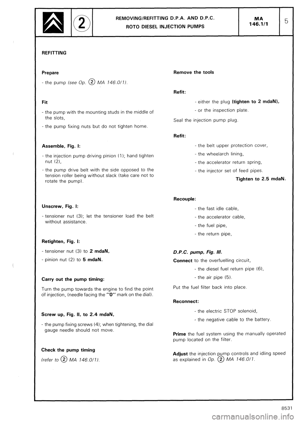
REFITTING
Prepare
- the pump (see Op. @ MA 146.0/l/
Fit
- the pump with the mounting studs in the middle of
the slots,
- the pump fixing nuts but do not tighten home.
Assemble, Fig. I:
- the injection pump driving pinion t I); hand tighten
nut (2),
- the pump drive belt with the side opposed to the
tension roller being without slack (take care not to
rotate the pump).
Unscrew, Fig. I:
- tensioner nut (3); let the tensioner load the belt
without assistance.
Retighten, Fig. I:
- tensioner nut (3) to 2 mdaN,
- pinion nut (2) to 5 mdaN.
Carry out the pump timing:
Turn the pump towards the engine to find the point
of injection, (needle facing the “0” mark on the dial).
Screw up, Fig. II, to 2.4 mdaN,
- the pump fixing screws (4); when tightening, the dial
gauge needle should not move.
Check the pump timing (refer to @ MA 146.011)
Remove the tools
Refit:
- either the plug (tighten to 2 mdaN),
- or the inspection plate.
Seal the injection pump plug.
Refit:
- the belt upper protection cover,
- the wheelarch lining,
- the accelerator return spring,
- the injector set of feed pipes.
Tighten to 2.5 mdaN.
Recouple:
- the fast idle cable,
- the accelerator cable,
- the fuel pipe,
- the return pipe, D.P.C. pump, Fig. III.
Connect to the overfuelling circuit,
- the diesel fuel return pipe (61,
- the air pipe (5).
Put the fuel filter back into place.
Reconnect:
- the electric STOP solenoid,
- the negative cable to the battery.
Prime the fuel system using the manually operated
pump located on the filter.
Adjust the injection pump controls and idling speed
as explained in Op. @ MA 146.0/l.
8531
Page 385 of 648

Connectors
l.-~l
a,
- Connectors
,”
9 r, 75 Colour
FiY
E
vl
-
M
M
V
V
V
V
M
M
-
N
v
V
M
N
V
-
V
M
V
V
V
-
M
V
2
$
R
V
M
Mv
B
N
BI
B
Mv . -
z
Y
i
r”
B
G Function Function
:
m
.e-
1
-
1
2
3
-
1
2
3
4
1
2
3
4
I
2
3
4
-
1 .-
f
-
M
M
M
-
N
N
M
-
B
B
V
G
N
-
N
M
-
V
V
-
-
M 1
2
3
-
-
-
-
1
2 -
3 -
6 -
4 -
4 -
4 -
3
1
3
-
9
-
6
-
9
-
2
L.
B
-
J
-
v
-
V
-
B
m
sg
ZD
‘N
B
-
B
-
B
-
B
-
V
-
-
-
B Eng. Oil Pressure Sensor
94
95
96 Choke
Diesel Pre Heating
Front Bulb Failure 84
I 8
1
Eng. Oil Sensor
V
J
J Low Fuel Warning Lamp
Fuel Gauge
Fuel Transmitter Earth “Stop” Warning
Hydraulic Warning
Eng. Oil Low Pressure Warning
Water Low Level Warning
Water Temp. Warning
” + Ignition Switch
Battery Charge Warning
Eng. Oil Temp. Warning
Water Low Temp. Warning
2 74
80
79
77
73
80
89
70
100
102
101
98
99
97
85
90
211
212
214
103
103
9
10
11 Instrument Lighting
L/H Dir. Ind. Warning
Seat Belt Warning
+ Ignition Switch (After F2)
Earth 107
R/H Dir. Ind. Warning 105
106
85
211
108
65
66
65 BI
Mv
M
B
Mv
3
L/H Rear Door Warning
Boot Door Warning
R/H Rear Door Warning
L/H Front Door Warning
R/H Front Door Warning
Bonnet Door Warning + Ignition Switch (After F.2)
Earth
Diesel TDC
Tachometer
4
B
G Turbo Pres. Warning
Anti-knock Warning 64
63
Yelow Warning
Red Warning econoscope
5
Brake Pad Wear Warning
Hand Brake Warning
Rear Fog Lamp Warning
Side Lamp Warning
Dipped Beam Warning
Main Beam Warning
Clogged Filter Warning
0 ic 6
R Earth
Test
Warning Rear Bulb
Failure
Unit 81
82
83
7
12 ?ABS Warning
+ Ignition Switch ABS