1988 CITROEN CX tow
[x] Cancel search: towPage 212 of 648

CHECKING AND ADJUSTING
THE INJECTION SYSTEM
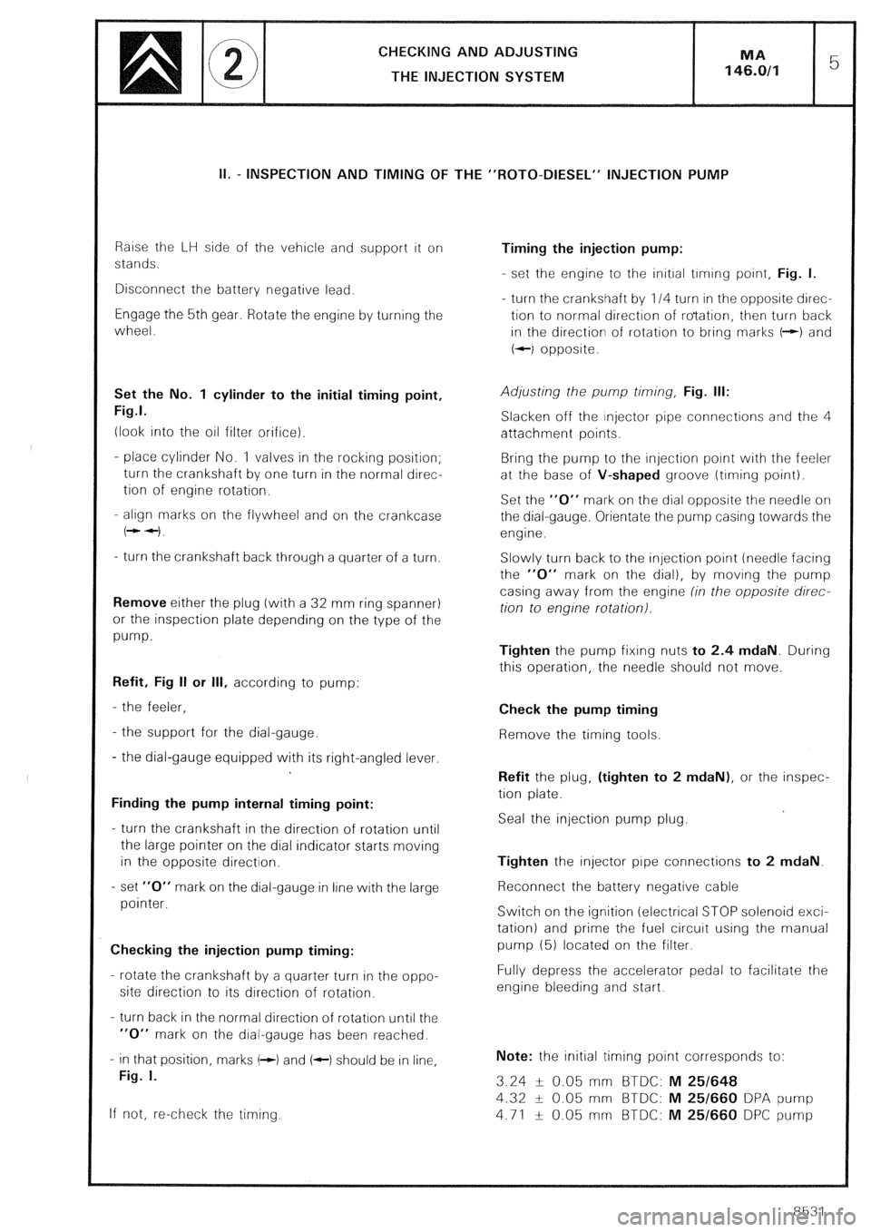
II. - INSPECTION AND TIMING OF THE “ROT0-DIESEL” INJECTION PUMP
Raise the LH side of the vehicle and support it on
stands.
Disconnect the battery negative lead.
Engage the 5th gear. Rotate the engine by turning the
wheel.
Set the No. 1 cylinder to the initial timing point,
Fig.1.
(look into the oil filter orifice).
- place cylinder No. 1 valves in the rocking position;
turn the crankshaft by one turn in the normal direc-
tion of engine rotation.
- align marks on the flywheel and on the crankcase
(++I.
- turn the crankshaft back through a quarter of a turn.
Remove either the plug (with a 32 mm ring spanner)
or the inspection plate depending on the type of the
pump.
Refit, Fig II or Ill, according to pump:
- the feeler,
- the support for the dial-gauge.
- the dial-gauge equipped with its right-angled lever.
Finding the pump internal timing point:
- turn the crankshaft in the direction of rotation until
the large pointer on the dial indicator starts moving
in the opposite direction.
- set “0” mark on the dial-gauge in line with the large
pointer.
Checking the injection pump timing:
- rotate the crankshaft by a quarter turn in the oppo-
site direction to its direction of rotation.
- turn back in the normal direction of rotation until the
“0” mark on the dial-gauge has been reached.
- in that position, marks (-1 and (c) should be in line,
Fig. I.
If not, re-check the timing. Timing the injection pump:
- set the engine to the initial trming point, Fig. I.
- turn the crankshaft by 114 turn in the opposite direc-
tion to normal direction of ro’tatron, then turn back
in the direction of rotation to bring marks t-+) and
+-I opposite.
Adjusting the pump timing, Fig. Ill:
Slacken off the injector pipe connections and the 4
attachment points.
Bring the pump to the injection point with the feeler
at the base of V-shaped groove (timing point).
Set the “0” mark on the dial opposite the needle on
the dial-gauge. Orientate the pump casing towards the
engine.
Slowly turn back to the injection point (needle facing
the “0” mark on the dial), by moving the pump
casing away from the engine (in the opposite direc-
tion to engine rotation).
Tighten the pump fixing nuts to 2.4 mdaN. During
this operation, the needle should not move.
Check the pump timing
Remove the timing tools.
Refit the plug, (tighten to 2 mdaN), or the inspec-
tion plate.
Seal the injection pump plug.
Tighten the injector pipe connections to 2 mdaN.
Reconnect the battery negative cable
Switch on the ignition (electrical STOP solenoid exci-
tation) and prime the fuel circuit using the manual
pump (5) located on the filter.
Fully depress the accelerator pedal to facilitate the
engine bleeding and start.
Note: the initial timing point corresponds to:
3.24 -L- 0.05 mm BTDC: M 25/648
4.32 + 0.05 mm BTDC: M 25/660 DPA pump
4.71 f 0.05 mm BTDC: M 25/660 DPC pump
8531
Page 218 of 648

REMOVING/REFITTING D.P.A. AND D.P.C.
ROT0 DIESEL INJECTION PUMPS MA
146.1/l 5
REFITTING
Prepare
- the pump (see Op. @ MA 146.0/l/
Fit
- the pump with the mounting studs in the middle of
the slots,
- the pump fixing nuts but do not tighten home.
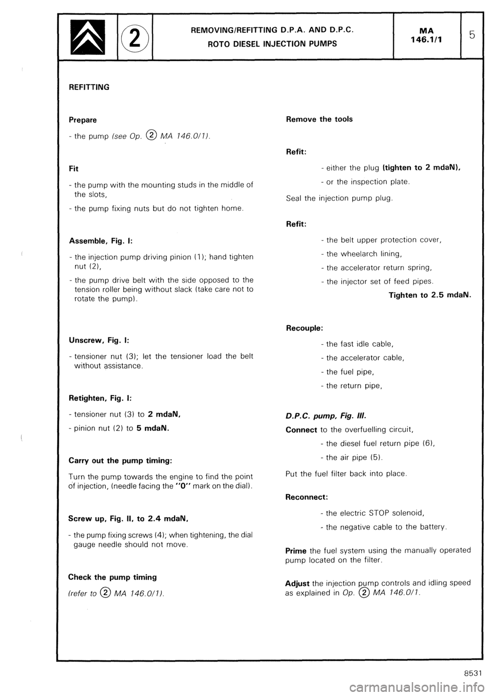
Assemble, Fig. I:
- the injection pump driving pinion t I); hand tighten
nut (2),
- the pump drive belt with the side opposed to the
tension roller being without slack (take care not to
rotate the pump).
Unscrew, Fig. I:
- tensioner nut (3); let the tensioner load the belt
without assistance.
Retighten, Fig. I:
- tensioner nut (3) to 2 mdaN,
- pinion nut (2) to 5 mdaN.
Carry out the pump timing:
Turn the pump towards the engine to find the point
of injection, (needle facing the “0” mark on the dial).
Screw up, Fig. II, to 2.4 mdaN,
- the pump fixing screws (4); when tightening, the dial
gauge needle should not move.
Check the pump timing (refer to @ MA 146.011)
Remove the tools
Refit:
- either the plug (tighten to 2 mdaN),
- or the inspection plate.
Seal the injection pump plug.
Refit:
- the belt upper protection cover,
- the wheelarch lining,
- the accelerator return spring,
- the injector set of feed pipes.
Tighten to 2.5 mdaN.
Recouple:
- the fast idle cable,
- the accelerator cable,
- the fuel pipe,
- the return pipe, D.P.C. pump, Fig. III.
Connect to the overfuelling circuit,
- the diesel fuel return pipe (61,
- the air pipe (5).
Put the fuel filter back into place.
Reconnect:
- the electric STOP solenoid,
- the negative cable to the battery.
Prime the fuel system using the manually operated
pump located on the filter.
Adjust the injection pump controls and idling speed
as explained in Op. @ MA 146.0/l.
8531
Page 222 of 648

SPECIFICATION AND SPECIAL FEATURES
OF THE AIR SUPPLY SYSTEM
Engines types 829.A5 and J6T.A500 are fitted with a device regulating the temperature of intake air.
This device has been designed for maintaining a minimum temperature of the air drawn into the carburettor
It consists of a thermal sensor and a vacuum capsule operating a flap. Thermal source
The thermal sensor is located in the pipe connecting the air filter to the inlet manifold of the carburettor
This bi-metal type thermostat, is subjected to the inlet air temperature
It controls the opening of valves allowing passage for a depression towards the capsule
This depression is picked up by a union having a calibrated orifice, fitted to the pipe connecting the oil breather
to the intake manifold of the carburettor, and by a T-shaped union situated near the carburettor base plate, so
as to have an action over the engine load.
The thermal sensor allows the depression to circulate when the temperature is below 15°C and stops it when the
temperature exceeds 25°C. Vacuum capsule.
The capsule, located in the inlet of the air filter, is subjected to the depression. When energised, it operates a flap
which lets the heated air coming from a tapping located on the exhaust shield enter. At rest, the flap lets intake
air coming from behind the grill enter.
Page 287 of 648

REMOVING AND REFITTING
AN UPPER WHEEL ARM
REMOVAL
Raise and support the front of the vehicle on stands
6602-T.
Depressurize the hydraulic circuit.
Set the height control lever to the (( low )) position
Remove, Fig. I :
- the wheel,
- the suspension cylinder pivot retaining pin (I 1,
- the anti-roll bar link rod nut (2).
Uncouple ball-joint (3) from the anti-roll bar link rod
using puller 6320-T. Fig. II.
Screw up the tool nut in the ball-joint stem. Fit the
tool cross piece and pin.
Extract, Fig. Ill,
- the nut from upper ball-joint (4).
Disconnect the upper ball-joint.
NOTE:
If the vehicle is fitted with the ABS, the removal of
the upper ball-joint nut requires pushing back the
transmission.
Remove:
- the pin, C
- the nut lock,
- the drive-shaft nut.
Fig. IV
- nut (51,
Fig. V
- the spindle with extractor 6303-T.
Remark: An adjustment shim may be found between
the arm and the front face of the subframe. REFITTING
The LH wheel arm is different from the RH one. Boss
u a )a should be directed towards the rear of the
vehicle when the wheel arm has been fitted.
Reinstall, Fig. V :
- the arm fitted with its thrust cups (7)
frhe thinner cup facing rearwardsl,
- the adjustment shim (6) found on dismantling, facing
forward.
Engage the spindle ; place a new NYLSTOP nut.
Tighten to 12.5 mdaN
Recouple the upper ball-joint.
Tighten the new NYLSTOP nut to 7 mdaN
Reconnect the anti-roll bar link rod (wipe the ball-joint
fixing but do nor use solventl.
Tighten the new NYLSTOP nut to 4.7 mdaN
Refit the suspension cylinder pivot and pin.
Vehicles equipped with the ABS:
Fit the drive-shaft nut (with the faces and threads
lubricated).
Tighten to 37.5 mdaN.
Replace:
- the nut lock,
- the pin,
- the road wheel