1988 CITROEN CX spark plugs
[x] Cancel search: spark plugsPage 20 of 648

RECOMMENDED PRODUCTS
IV - GREASES AND LUBRICANTS
PRODUCT
USE AND SPECIAL FEATURES AND SYMBOL MARK SUPPLIER
R.P. No.
High adhesive grease: 95 615 129 R.P.D.
- Intended mainly for drive-shaft lubrication.
GRAISSE 1495 Gl MOLY DAL
- Can be used for mechanisms working under difficult
conditions (high pressures, splashed water). MOLYKOTE
LONGTERM 2 DOW-CORNING
Grease resisting high temperatures:
GRIPCOTT AF G2
- For exhaust manifold ball-joints. MOLYDAL
Lubricant for parts working under difficult
conditions:
HI LUB-HTC G3 FRAM ET
- Splashed water, high pressure and temperature.
Grease resisting high temperatures:
- To lubricate the threaded spark plugs fitted to the NO-BIND G4 CURTY *
cylinder head.
Multifunctional lubricant:
M.O.
G5
- Molybdenum disulfide-base product. TEROSON
Multifunctional grease:
- For routine works. TOTAL MULTIS G6 TOTAL C.F.R.
Special grease: PROBA. 270
ALTEMP G7 R.P.D.
- Designed for anti-roll bar bearings.
79.01973.067
Animal grease:
- Tallow. GB
Special grease: ESSO
- To be used for fitting the road wheel sensors of the NORVA G9 R.P.D.
anti-locking brake system. 275
8531
Page 102 of 648

Raise ihe vei-~cle front end
Shift in the i-\~yi-\est gear. Move the crankshaft using
t!le R.H. road wheel.
Remove, Fig. I:
- inlet pipes (I 1,
- tilt: cyllnderlleati CoveI,
- the sparkIng plugs
o. 4 piston to TDC
(with the valves in the “rocking” position).
Place tool 1682-T fitted with a dial indicator In
cylinder No. 1, Fig. II.
Firlti ihe TDC.
Adjust cylinder No. 1 lrllel valve (2) clearance to
1.10 mm, Fig. II.
Rotate the cl-ankshaft through a complete turn In the
normal direction of engine rotation.
Record the clearance of cylirlder No. 1 inlet valve:
the figure should be comprised between :
0.05 and 0.25 mm eck and adlust ihe valve locker clearances.
Inlet = 0.15 mm
Exhaust = 0.20 mm
Refit:
- the cylinderhead cover,
the inlet pipes,
- the spark plugs (tightening torque: 2.5 mdaN),
Lower the vehicle to the ground
Page 157 of 648

GENERAL FEATURES OF THE CARBURATION
FITTING. Fig. I:
5. FIN the tamper-proof protective plug (a):
- load gun A,
- screw tool E onto gun A,
- position plug (a) in its housing on the carburettor (make sure it is fitted the right way round Fig. 111,
- actuate the gun until the plug is properly located.
EXHAUST EMISSION CONTROL
In order to comply with current regulations, the checking and adjustment of the exhaust emission from vehicles
with a petrol engine must, without fail, be performed after the following operations:
I. ENGINE REPLACEMENT.
II. CARBURETTOR REPLACEMENT.
Ill. WORK ON THE CARBURETTOR.
Replacement of parts of the carburettor.
Carburettor adjustment.
Work on the carburettor controls.
IV. WORK ON THE INLET MANIFOLD.
Replacement or removal of:
- the inlet manifold,
- the air filter,
- crankcase gas recirculation system
V. WORK ON THE ENGINE.
Rocker adjustment.
Replacement or removal of:
- the cylinder head,
- the camshaft,
- the rockers,
- the valves,
- the liners and pistons.
VI. WORK ON THE IGNITION.
Replacement or reconditioning of the distributor (wholly or partially)
Adjustment or replacement of the sparking plugs.
Adjustment of the ignition timing.
VII. WORK ON EXHAUST SYSTEM.
Replacement or removal of:
- the exhaust manifold,
- the silencer or any part of the exhaust.
VIII. WORK ON THE EMISSION CONTROL SYSTEM.
When the vehicle is fitted with a specific equipment (e.g. on vehicles of SWEDEN, AUSTRALlA or JAPAN type)
Page 256 of 648

CHECKlNG THE TRANSISTORISED IGNITION
ELECTRO-MAGNETICALLY TRIGGERED TRANSISTORISED IGNITION
PRELIMINARY CHECKS:
Inspect:
- the connection of the different leads (in particular to coil: a bad connection can cause a high voltage drop preven-
ting the current from passing into the coil primary winding (I 5 A approx),
- condition of the leads : (circuits broken, short-circuits across screening, etc.),
- condition of the sparking plugs (deposits, cracks due to overtightening),
- condition of the distributor cap (wear, cracks) and the rotor arm (loose).
Disconnect the interference suppression capacitor and the diagnosis harness, from the circuit.
Carry out a ((spark test)) with the starter motor and one plug earthed.
IMPORTANT: The module may be destroyed if one of the secondary wires is too far from the earth. CHECKING THE COIL (3) (ignition module and supply to coil disconnected):
MEASUREMENT OF Ohmmeter placed between channels No. Reading (in 0)
Primary winding resistance 1 and 4 DUCELLIER 0.76 to 0.84
BOSCH 0.74 to 0.90
Secondary coil resistance 1 4 and HT coil contact DUCELLIER 5700 to 6300
or
BOSCH 7425 to 9075
Insulation 1 or 4 and earth 00
Checking the coil power supply using a lamp or a voltmeter:
- Switch on the ignition: there should be a 12V current between the “BAT” terminal of the coil and the earth
- Switch off ignition. CHECKING THE IGNITION MODULE (2):
The module is designed to function with the ignition distributor and the coil.
- Do not operate the module without cooling (aluminium plate heat sink) or ventilation
- Do not check the module with an ohmmeter since the results will be non-significant.
Checking the module power supply using a lamp or a voltmeter:
- Disconnect the module connector
- Switch on the ignition: there should be a 12 V current between the channel 4 of the connector and the earth.
- Switch off ignition.
The low voltage ignition circuit being connected (in working order), disconnect the coil - distributor HT lead on
the distributor side and connect it up to an earthed plug: by sending short pulses ( + 12 VI to channel 5 (red wire)
from the module, sparks should occur at the plug (simulation of distributor spark current). CHECKING THE IGNITION DISTRIBUTOR (1):
Test the impulse generator with the module connector disconnected. MEASUREMENT OF:
Resistance
Earth
Insulation Ohmmeter placed between channels No. 5 and 6
2 and engine earth
5 and 2 then 5 and 3 Readings (in Q) 950 to 1250 approx.
0
m
,
Page 259 of 648

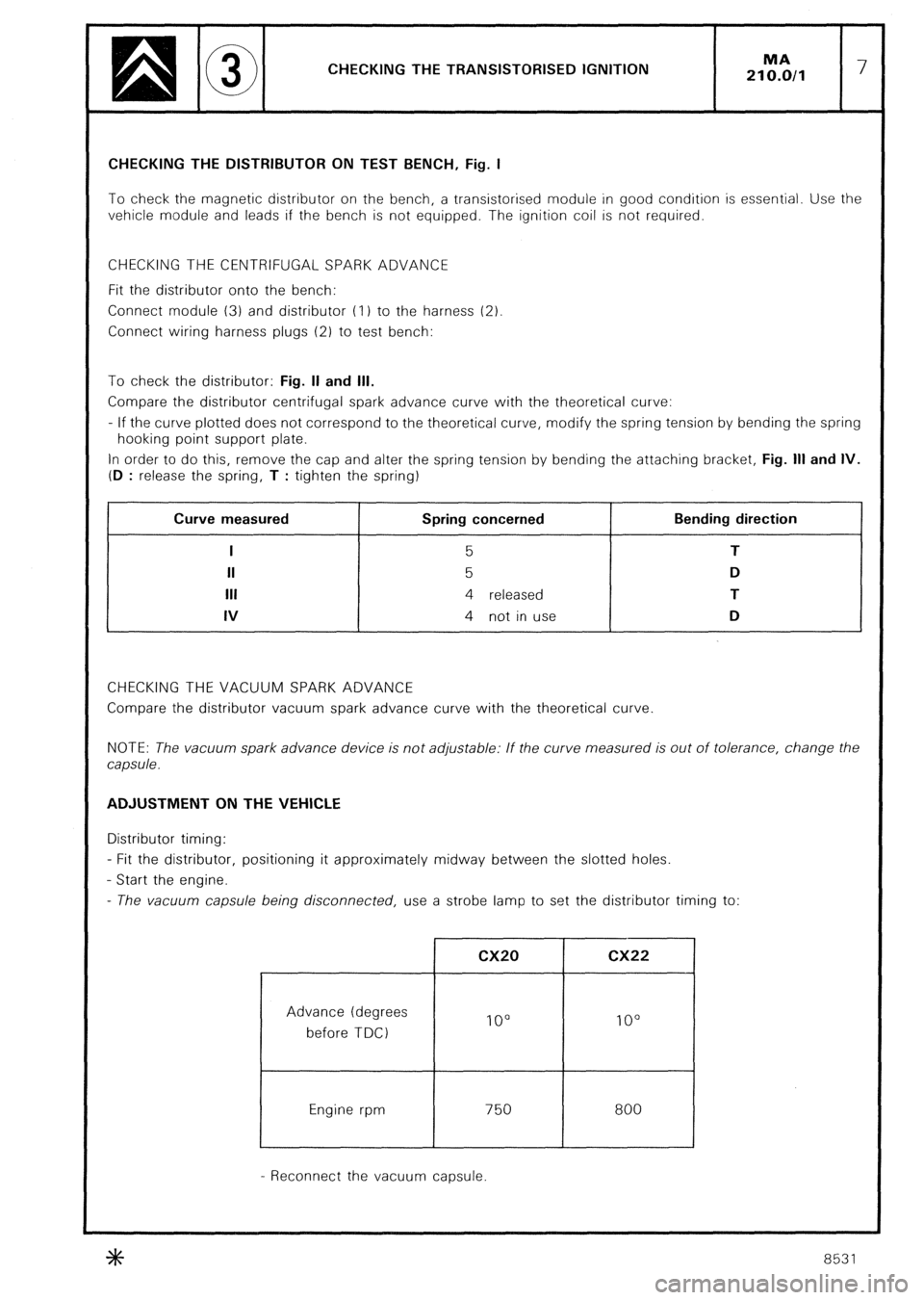
CHECKING THE TRANSISTORISED IGNITION MA
210.0/l 7 CHECKING THE DISTRIBUTOR ON TEST BENCH, Fig. I
To check the magnetic distributor on the bench, a transistorised module in good condition is essential. Use the
vehicle module and leads if the bench is not equipped. The ignition coil is not required.
CHECKING THE CENTRIFUGAL SPARK ADVANCE
Fit the distributor onto the bench:
Connect module (3) and distributor (I 1 to the harness (2)
Connect wiring harness plugs (2) to test bench:
To check the distributor: Fig. II and Ill.
Compare the distributor centrifugal spark advance curve with the theoretical curve:
- If the curve plotted does not correspond to the theoretical curve, modify the spring tension by bending the spring
hooking point support plate.
In order to do this, remove the cap and alter the spring tension by bending the attaching bracket, Fig. Ill and IV.
(D
: release the spring, T : tighten the spring) , Curve measured
I
II
Ill
IV Spring concerned
5
5
4 released
4 not in use Bending direction
T
D
T
D
CHECKING THE VACUUM SPARK ADVANCE
Compare the distributor vacuum spark advance curve with the theoretical curve
NOTE: The vacuum spark advance device is not adjustable: If the curve measured is out of tolerance, change the
capsule. ADJUSTMENT ON THE VEHICLE
Distributor timing:
- Fit the distributor, positioning it approximately midway between the slotted holes.
- Start the engine.
- The vacuum capsule being disconnected, use a strobe lamp to set the distributor timing to:
Advance (degrees
before TDC)
Engine rpm cx20 cx22
IO0 lo0
750
I 800
- Reconnect the vacuum capsule.
8531
Page 260 of 648

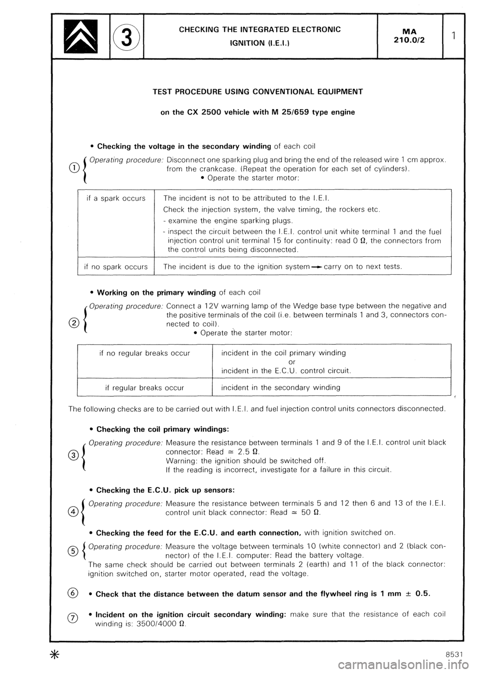
CHECKING THE INTEGRATED ELECTRONlC
IGNITION (I.E.I.)
TEST PROCEDURE USING CONVENTIONAL EQUIPMENT
on the CX 2500 vehicle with M 25/659 type engine
l Checking the voltage in the secondary winding of each coil
0 Operating procedure: Disconnect one sparking plug and bring the end of the released wire 1 cm approx
from the crankcase. (Repeat the operation for each set of cylinders).
l Operate the starter motor:
if a spark occurs The incident is not to be attributed to the I.E.I.
Check the injection system, the valve timing, the rockers etc.
- examine the engine sparking plugs.
- inspect the circuit between the I.E.I. control unit white terminal 1 and the fuel
injection control unit terminal 15 for continuity: read 0 0, the connectors from
the control units being disconnected.
if no spark occurs The incident is due to the ignition system--ccarry on to next tests.
l Working on the primary winding of each coil
Operating procedure: Connect a 12V warning lamp of the Wedge base type between the negative and
0 the positive terminals of the coil (i.e. between terminals 1 and 3, connectors con-
netted to coil).
l Operate the starter motor:
if no regular breaks occur incident in the coil primary winding
or
incident in the E.C.U. control circuit.
if regular breaks occur incident in the secondary winding
The following checks are to be carried out with I.E.I. and fuel injection control units connectors disconnected.
l Checking the coil primary windings:
Operating procedure: Measure the resistance between terminals 1 and 9 of the I.E.I. control unit black
0 connector: Read = 2.5 0.
Warning: the ignition should be switched off.
If the reading is incorrect, investigate for a failure in this circuit.
l Checking the E.C.U. pick up sensors:
co Operating procedure: Measure the resistance between terminals 5 and 12 then 6 and 13 of the I.E.I.
control unit black connector: Read = 50 a.
l Checking the feed for the E.C.U. and earth connection, with ignition switched on
Operating procedure: Measure the voltage between terminals IO (white connector) and 2 (black con-
nector) of the I.E.I. computer: Read the battery voltage.
The same check should be carried out between terminals 2 (earth) and 11 of the black connector:
ignition switched on, starter motor operated, read the voltage.
69 l Check that the distance between the datum sensor and the flywheel ring is 1 mm + 0.5.
0 l Incident on the ignition circuit secondary winding: make sure that the resistance of each coil
winding is: 350014000 a.
8531
Page 261 of 648

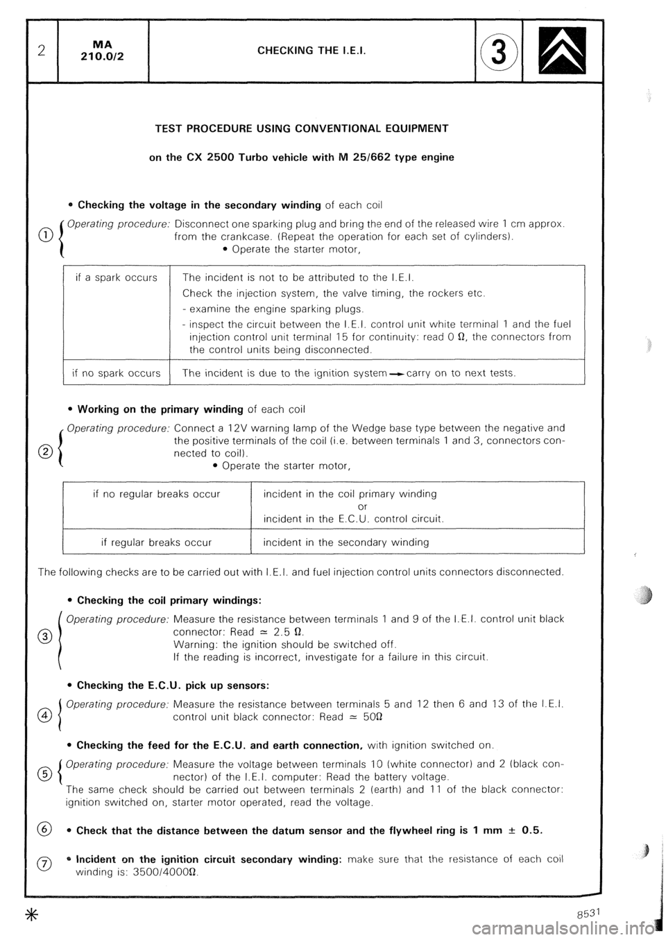
CHECKING THE I.E.I.
TEST PROCEDURE USING CONVENTIONAL EQUIPMENT
on the CX 2500 Turbo vehicle with M 25/662 type engine
0 Checking the voltage in the secondary winding of each coil
0 Operating procedure: Disconnect one sparking plug and bring the end of the released wire 1 cm approx
from the crankcase. (Repeat the operation for each set of cylinders).
0 Operate the starter motor,
if a spark occurs
if no spark occurs The incident is not to be attributed to the I.E.I.
Check the injection system, the valve timing, the rockers etc.
- examine the engine sparking plugs.
- inspect the circuit between the I.E.I. control unit white terminal 1 and the fuel
injection control unit terminal 15 for continuity: read 0 Q, the connectors from
the control units being disconnected.
The incident is due to the ignition system-carry on to next tests.
l Working on the primary winding of each coil
Operating procedure: Connect a 12V warning lamp of the Wedge base type between the negative and
the positive terminals of the coil (i.e. between terminals 1 and 3, connectors con-
netted to coil).
l Operate the starter motor,
if no regular breaks occur incident in the coil primary winding
or
incident in the E.C.U. control circuit.
if regular breaks occur incident in the secondary winding
The following checks are to be carried out with I.E.I. and fuel injection control units connectors disconnected.
0 Checking the coil primary windings:
Operating procedure: Measure the resistance between terminals 1 and 9 of the I.E.I. control unit black
0 connector: Read = 2.5 Q.
Warning: the ignition should be switched off.
If the reading is incorrect, investigate for a failure in this circuit.
l Checking the E.C.U. pick up sensors:
OI Operating procedure: Measure the resistance between terminals 5 and 12 then 6 and 13 of the I.E.I.
4
control unit black connector: Read 2: 5OQ
0 Checking the feed for the E.C.U. and earth connection, with ignition switched on.
d 5 Operating procedure: Measure the voltage between terminals 10 (white connector) and 2 (black con-
nectar) of the I.E.I. computer: Read the battery voltage.
The same check should be carried out between terminals 2 (earth) and 11 of the black connector:
ignition switched on, starter motor operated, read the voltage.
@ 0 Check that the distance between the datum sensor and the flywheel ring is 1 mm + 0.5.
0 * Incident on the ignition circuit secondary winding: make sure that the resistance of each coil
winding is: 350014OOOQ.