1988 CITROEN CX checking oil
[x] Cancel search: checking oilPage 212 of 648
CHECKING AND ADJUSTING
THE INJECTION SYSTEM
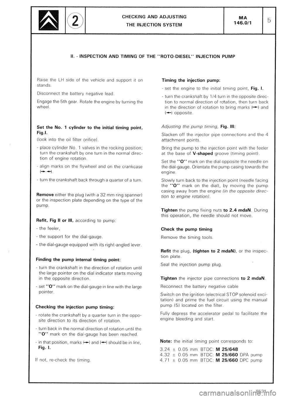
II. - INSPECTION AND TIMING OF THE “ROT0-DIESEL” INJECTION PUMP
Raise the LH side of the vehicle and support it on
stands.
Disconnect the battery negative lead.
Engage the 5th gear. Rotate the engine by turning the
wheel.
Set the No. 1 cylinder to the initial timing point,
Fig.1.
(look into the oil filter orifice).
- place cylinder No. 1 valves in the rocking position;
turn the crankshaft by one turn in the normal direc-
tion of engine rotation.
- align marks on the flywheel and on the crankcase
(++I.
- turn the crankshaft back through a quarter of a turn.
Remove either the plug (with a 32 mm ring spanner)
or the inspection plate depending on the type of the
pump.
Refit, Fig II or Ill, according to pump:
- the feeler,
- the support for the dial-gauge.
- the dial-gauge equipped with its right-angled lever.
Finding the pump internal timing point:
- turn the crankshaft in the direction of rotation until
the large pointer on the dial indicator starts moving
in the opposite direction.
- set “0” mark on the dial-gauge in line with the large
pointer.
Checking the injection pump timing:
- rotate the crankshaft by a quarter turn in the oppo-
site direction to its direction of rotation.
- turn back in the normal direction of rotation until the
“0” mark on the dial-gauge has been reached.
- in that position, marks (-1 and (c) should be in line,
Fig. I.
If not, re-check the timing. Timing the injection pump:
- set the engine to the initial trming point, Fig. I.
- turn the crankshaft by 114 turn in the opposite direc-
tion to normal direction of ro’tatron, then turn back
in the direction of rotation to bring marks t-+) and
+-I opposite.
Adjusting the pump timing, Fig. Ill:
Slacken off the injector pipe connections and the 4
attachment points.
Bring the pump to the injection point with the feeler
at the base of V-shaped groove (timing point).
Set the “0” mark on the dial opposite the needle on
the dial-gauge. Orientate the pump casing towards the
engine.
Slowly turn back to the injection point (needle facing
the “0” mark on the dial), by moving the pump
casing away from the engine (in the opposite direc-
tion to engine rotation).
Tighten the pump fixing nuts to 2.4 mdaN. During
this operation, the needle should not move.
Check the pump timing
Remove the timing tools.
Refit the plug, (tighten to 2 mdaN), or the inspec-
tion plate.
Seal the injection pump plug.
Tighten the injector pipe connections to 2 mdaN.
Reconnect the battery negative cable
Switch on the ignition (electrical STOP solenoid exci-
tation) and prime the fuel circuit using the manual
pump (5) located on the filter.
Fully depress the accelerator pedal to facilitate the
engine bleeding and start.
Note: the initial timing point corresponds to:
3.24 -L- 0.05 mm BTDC: M 25/648
4.32 + 0.05 mm BTDC: M 25/660 DPA pump
4.71 f 0.05 mm BTDC: M 25/660 DPC pump
8531
Page 256 of 648

CHECKlNG THE TRANSISTORISED IGNITION
ELECTRO-MAGNETICALLY TRIGGERED TRANSISTORISED IGNITION
PRELIMINARY CHECKS:
Inspect:
- the connection of the different leads (in particular to coil: a bad connection can cause a high voltage drop preven-
ting the current from passing into the coil primary winding (I 5 A approx),
- condition of the leads : (circuits broken, short-circuits across screening, etc.),
- condition of the sparking plugs (deposits, cracks due to overtightening),
- condition of the distributor cap (wear, cracks) and the rotor arm (loose).
Disconnect the interference suppression capacitor and the diagnosis harness, from the circuit.
Carry out a ((spark test)) with the starter motor and one plug earthed.
IMPORTANT: The module may be destroyed if one of the secondary wires is too far from the earth. CHECKING THE COIL (3) (ignition module and supply to coil disconnected):
MEASUREMENT OF Ohmmeter placed between channels No. Reading (in 0)
Primary winding resistance 1 and 4 DUCELLIER 0.76 to 0.84
BOSCH 0.74 to 0.90
Secondary coil resistance 1 4 and HT coil contact DUCELLIER 5700 to 6300
or
BOSCH 7425 to 9075
Insulation 1 or 4 and earth 00
Checking the coil power supply using a lamp or a voltmeter:
- Switch on the ignition: there should be a 12V current between the “BAT” terminal of the coil and the earth
- Switch off ignition. CHECKING THE IGNITION MODULE (2):
The module is designed to function with the ignition distributor and the coil.
- Do not operate the module without cooling (aluminium plate heat sink) or ventilation
- Do not check the module with an ohmmeter since the results will be non-significant.
Checking the module power supply using a lamp or a voltmeter:
- Disconnect the module connector
- Switch on the ignition: there should be a 12 V current between the channel 4 of the connector and the earth.
- Switch off ignition.
The low voltage ignition circuit being connected (in working order), disconnect the coil - distributor HT lead on
the distributor side and connect it up to an earthed plug: by sending short pulses ( + 12 VI to channel 5 (red wire)
from the module, sparks should occur at the plug (simulation of distributor spark current). CHECKING THE IGNITION DISTRIBUTOR (1):
Test the impulse generator with the module connector disconnected. MEASUREMENT OF:
Resistance
Earth
Insulation Ohmmeter placed between channels No. 5 and 6
2 and engine earth
5 and 2 then 5 and 3 Readings (in Q) 950 to 1250 approx.
0
m
,
Page 259 of 648
CHECKING THE TRANSISTORISED IGNITION MA
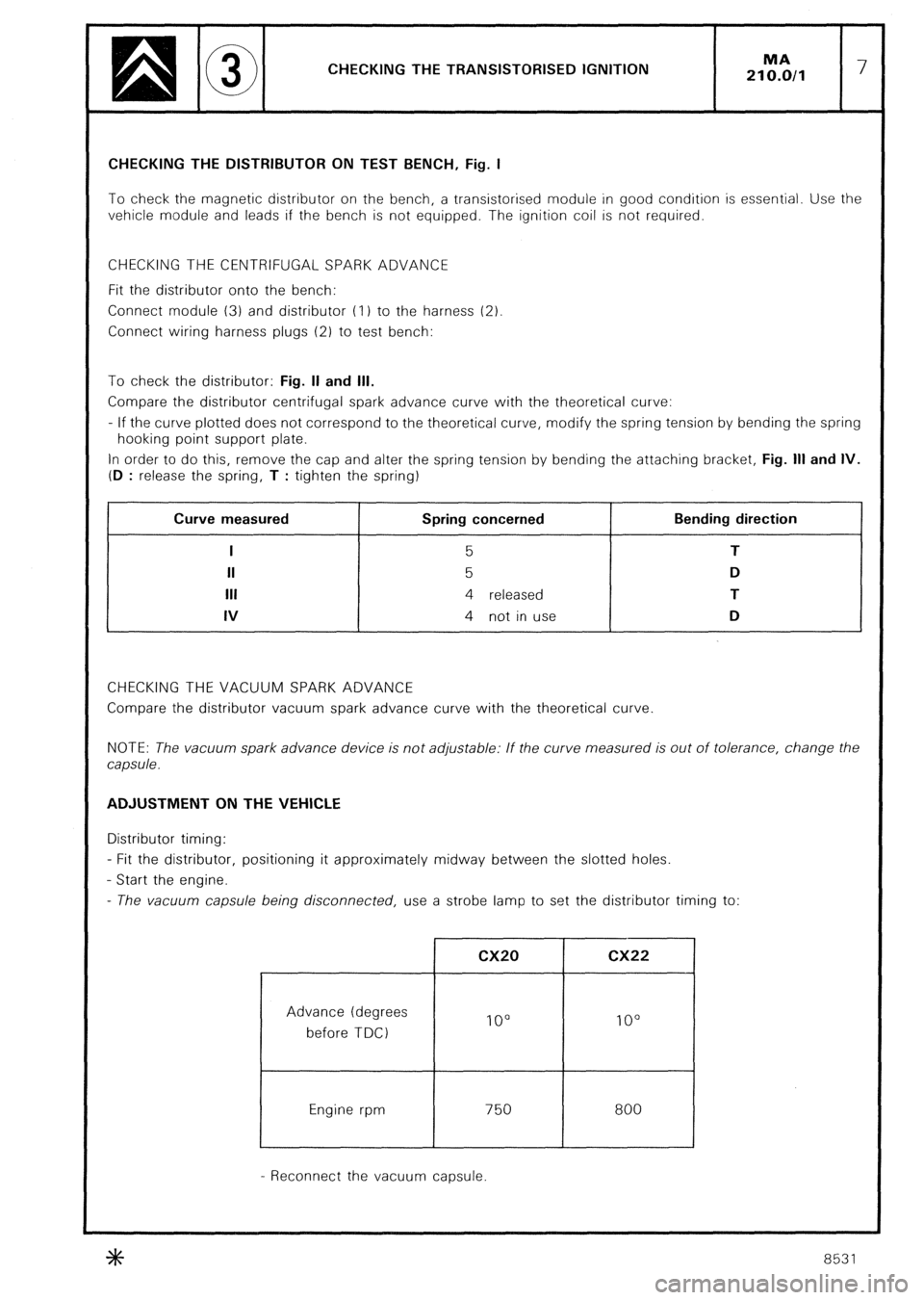
210.0/l 7 CHECKING THE DISTRIBUTOR ON TEST BENCH, Fig. I
To check the magnetic distributor on the bench, a transistorised module in good condition is essential. Use the
vehicle module and leads if the bench is not equipped. The ignition coil is not required.
CHECKING THE CENTRIFUGAL SPARK ADVANCE
Fit the distributor onto the bench:
Connect module (3) and distributor (I 1 to the harness (2)
Connect wiring harness plugs (2) to test bench:
To check the distributor: Fig. II and Ill.
Compare the distributor centrifugal spark advance curve with the theoretical curve:
- If the curve plotted does not correspond to the theoretical curve, modify the spring tension by bending the spring
hooking point support plate.
In order to do this, remove the cap and alter the spring tension by bending the attaching bracket, Fig. Ill and IV.
(D
: release the spring, T : tighten the spring) , Curve measured
I
II
Ill
IV Spring concerned
5
5
4 released
4 not in use Bending direction
T
D
T
D
CHECKING THE VACUUM SPARK ADVANCE
Compare the distributor vacuum spark advance curve with the theoretical curve
NOTE: The vacuum spark advance device is not adjustable: If the curve measured is out of tolerance, change the
capsule. ADJUSTMENT ON THE VEHICLE
Distributor timing:
- Fit the distributor, positioning it approximately midway between the slotted holes.
- Start the engine.
- The vacuum capsule being disconnected, use a strobe lamp to set the distributor timing to:
Advance (degrees
before TDC)
Engine rpm cx20 cx22
IO0 lo0
750
I 800
- Reconnect the vacuum capsule.
8531
Page 260 of 648
CHECKING THE INTEGRATED ELECTRONlC
IGNITION (I.E.I.)
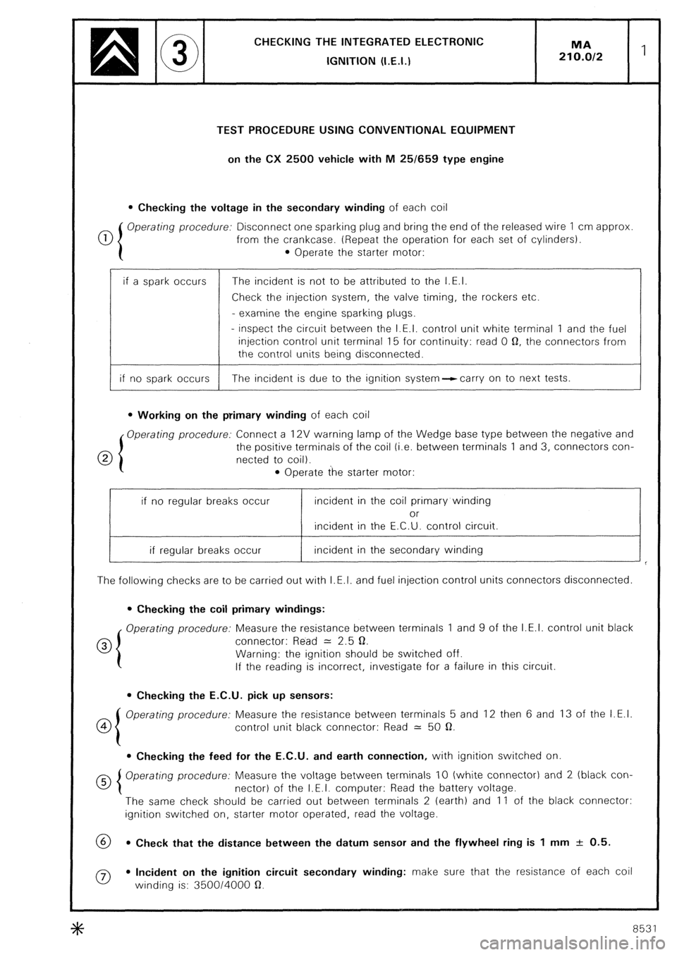
TEST PROCEDURE USING CONVENTIONAL EQUIPMENT
on the CX 2500 vehicle with M 25/659 type engine
l Checking the voltage in the secondary winding of each coil
0 Operating procedure: Disconnect one sparking plug and bring the end of the released wire 1 cm approx
from the crankcase. (Repeat the operation for each set of cylinders).
l Operate the starter motor:
if a spark occurs The incident is not to be attributed to the I.E.I.
Check the injection system, the valve timing, the rockers etc.
- examine the engine sparking plugs.
- inspect the circuit between the I.E.I. control unit white terminal 1 and the fuel
injection control unit terminal 15 for continuity: read 0 0, the connectors from
the control units being disconnected.
if no spark occurs The incident is due to the ignition system--ccarry on to next tests.
l Working on the primary winding of each coil
Operating procedure: Connect a 12V warning lamp of the Wedge base type between the negative and
0 the positive terminals of the coil (i.e. between terminals 1 and 3, connectors con-
netted to coil).
l Operate the starter motor:
if no regular breaks occur incident in the coil primary winding
or
incident in the E.C.U. control circuit.
if regular breaks occur incident in the secondary winding
The following checks are to be carried out with I.E.I. and fuel injection control units connectors disconnected.
l Checking the coil primary windings:
Operating procedure: Measure the resistance between terminals 1 and 9 of the I.E.I. control unit black
0 connector: Read = 2.5 0.
Warning: the ignition should be switched off.
If the reading is incorrect, investigate for a failure in this circuit.
l Checking the E.C.U. pick up sensors:
co Operating procedure: Measure the resistance between terminals 5 and 12 then 6 and 13 of the I.E.I.
control unit black connector: Read = 50 a.
l Checking the feed for the E.C.U. and earth connection, with ignition switched on
Operating procedure: Measure the voltage between terminals IO (white connector) and 2 (black con-
nector) of the I.E.I. computer: Read the battery voltage.
The same check should be carried out between terminals 2 (earth) and 11 of the black connector:
ignition switched on, starter motor operated, read the voltage.
69 l Check that the distance between the datum sensor and the flywheel ring is 1 mm + 0.5.
0 l Incident on the ignition circuit secondary winding: make sure that the resistance of each coil
winding is: 350014000 a.
8531
Page 261 of 648
CHECKING THE I.E.I.
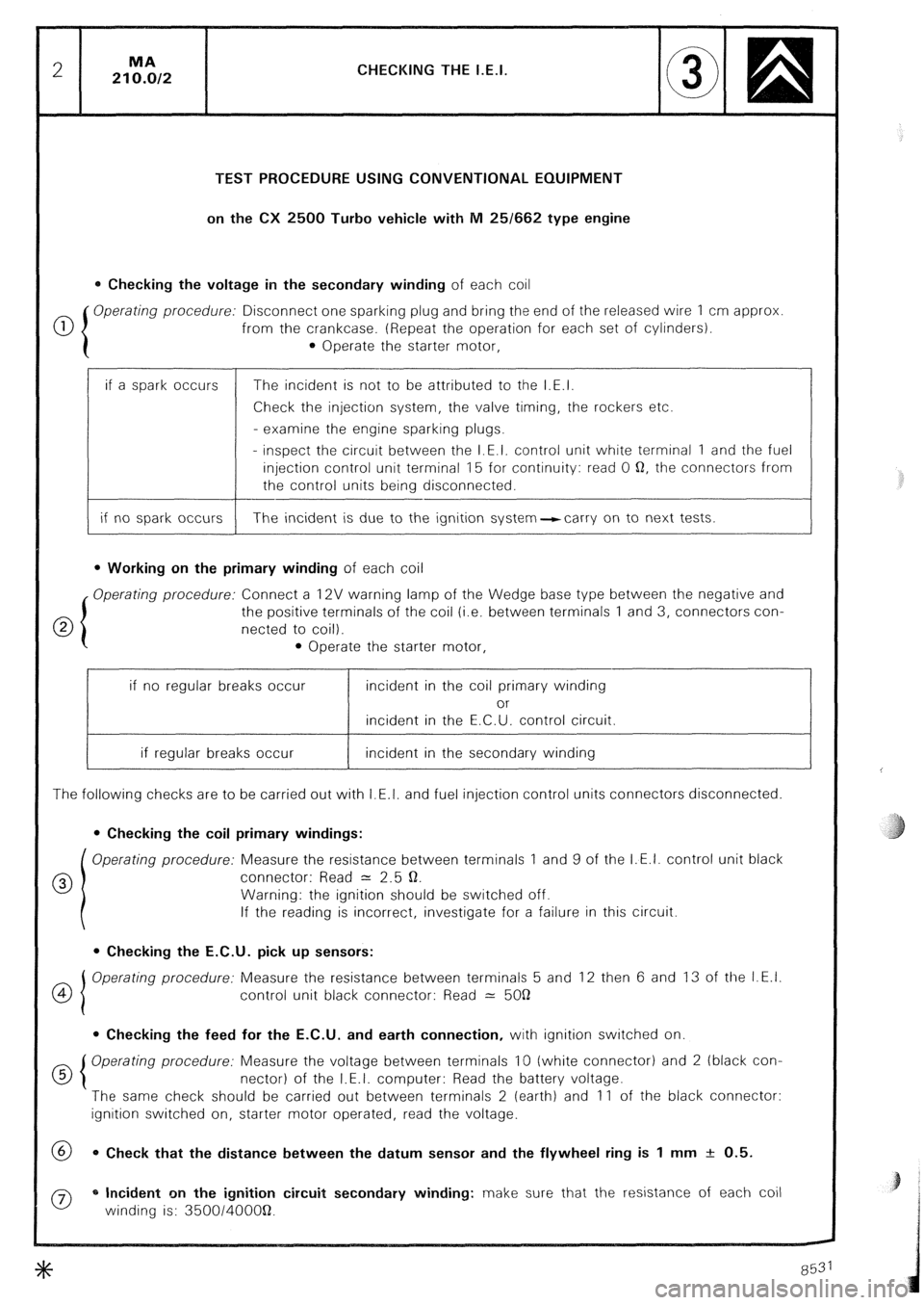
TEST PROCEDURE USING CONVENTIONAL EQUIPMENT
on the CX 2500 Turbo vehicle with M 25/662 type engine
0 Checking the voltage in the secondary winding of each coil
0 Operating procedure: Disconnect one sparking plug and bring the end of the released wire 1 cm approx
from the crankcase. (Repeat the operation for each set of cylinders).
0 Operate the starter motor,
if a spark occurs
if no spark occurs The incident is not to be attributed to the I.E.I.
Check the injection system, the valve timing, the rockers etc.
- examine the engine sparking plugs.
- inspect the circuit between the I.E.I. control unit white terminal 1 and the fuel
injection control unit terminal 15 for continuity: read 0 Q, the connectors from
the control units being disconnected.
The incident is due to the ignition system-carry on to next tests.
l Working on the primary winding of each coil
Operating procedure: Connect a 12V warning lamp of the Wedge base type between the negative and
the positive terminals of the coil (i.e. between terminals 1 and 3, connectors con-
netted to coil).
l Operate the starter motor,
if no regular breaks occur incident in the coil primary winding
or
incident in the E.C.U. control circuit.
if regular breaks occur incident in the secondary winding
The following checks are to be carried out with I.E.I. and fuel injection control units connectors disconnected.
0 Checking the coil primary windings:
Operating procedure: Measure the resistance between terminals 1 and 9 of the I.E.I. control unit black
0 connector: Read = 2.5 Q.
Warning: the ignition should be switched off.
If the reading is incorrect, investigate for a failure in this circuit.
l Checking the E.C.U. pick up sensors:
OI Operating procedure: Measure the resistance between terminals 5 and 12 then 6 and 13 of the I.E.I.
4
control unit black connector: Read 2: 5OQ
0 Checking the feed for the E.C.U. and earth connection, with ignition switched on.
d 5 Operating procedure: Measure the voltage between terminals 10 (white connector) and 2 (black con-
nectar) of the I.E.I. computer: Read the battery voltage.
The same check should be carried out between terminals 2 (earth) and 11 of the black connector:
ignition switched on, starter motor operated, read the voltage.
@ 0 Check that the distance between the datum sensor and the flywheel ring is 1 mm + 0.5.
0 * Incident on the ignition circuit secondary winding: make sure that the resistance of each coil
winding is: 350014OOOQ.
Page 264 of 648
CHECKING THE IGNITION SYSTEM
USING CHECKING EQUIPMENT OUT 106 029T
The instrument can be utilised on CX 2400 I.E. with naturally aspirated engine and CX 2500 I.E. TURBO. Howe-
ver, on CX 2400 I.E. having an integrated electronic ignition system with a single connector E.C.U., it is neces-
sary to proceed as follows:
- connect the I.E.I. control unit to the black connector of OUT 105 029.T
- set the switch of the apparatus to the “1 connector” position
- I.E.I. with 1 or 2 sensors can be checked with this device.
a) Testing the ignition coil primary winding:
- The warning lamps, one at each coil, blink rythmically with the impulses transmitted to their primary win-
ding. Steady blinks indicate that there is enough current to generate a spark in the secondary winding.
- The switch situated under the warning lamps makes it possible for the primary windings of both coils to
be insulated, by pushing, in the “out of circuit“ position, any interference coming from the HT circuit when
the frequency of illumination for sensor warning lamps is checked.
- If the warning lamps blinking is correct, the failure may be caused by:
- the ignition information to the fuel injection control unit, (paragraph c),
- the secondary winding (coil wires, coils),
- any other item required for a correct operation of the engine such as injection, valve gear, rockers etc.) -
If the warning lamps blinking is not correct, examine the control unit warning lamps, (paragraph b),
b) Testing the sensors: -
The warning lamp connected with the “datum” sensor blinks rythmically with the impulses transmitted by
the peg, i.e. one blink per engine revolution, (2 sensors fitted).
- The warning lamp connected with the “flywheel pick up” sensor, blinks rythmically with the impulses sent ’
by the flywheel teeth.
The frequency of the flashes is such as they can hardly be seen.
Apparently, the lamp stays on, (1 or 2 sensors fitted).
On the CX 2400 I.E. and 2500 I.E. with normally aspirated engine, the vacuum pressure warning lamp lights
up momentarily after a sharp acceleration: this warning lamp is no longer usable on the CX 2500 I.E. with
turbocharger.
c) Tests related with the I.E.I. control unit:
E.C.U. functions: -
The rev. counter warning lamp blinks rythmically with the impulses transmitted to the rev. counter.
- The injection warning lamp blinks rythmically with the impulses sent to the fuel injection control unit
+k 8531
Page 319 of 648

REPAIR OF THE HYDRAULIC SYSTEM
FITTING PRECAUTIONS
5. PRECAUTIONS TO BE TAKEN BEFORE WORKING ON THE HYDRAULIC SYSTEM:
a) Carrefully clean the aera of work, the unions and the unit to be removed
- Disconnect the lead from the negative terminal of the battery.
- Only use petrol or lead-free petrol cleaning.
b) Release the pressure in the circuits:
- Place the vehicle in the K/OW~~ position.
- Slacken the pressure regulator release screw (by one turn to one turn and a half, do not remove the screw:
the sealing ball (21, see Fig. I and II page 5, could get lost,
- Wait until the front of the car has reached the low position. 6. PRECAUTIONS TO BE TAKEN DURING REMOVAL.
a) Blank off the metal pipes with plugs, and rubber tubes with round pins of the correct diameter
b) Blank off the openings of components with plugs of the correct diameter.
NOTE: Plugs and pins must be carefully cleaned before insertion 7. CHECK OR TEST OF HYDRAULIC UNITS:
- use 4034-T test bench equipped and designed for use with LHM fluid.
- This bench is painted green and its accessories are marked in green.
- Never use the bench with another fluid or for testing components operating with another fluid (units of a c(D))
car using LHS 2 for instance).
NOTE: The uLe Bozec)) pump used on test benches for checking DIESEL injectors can be resorted to for testing,
components operating with LHM mineral fluid provided that the bench is cleaned first. 8. PRECAUTIONS TO BE TAKEN DURING REFITTING.
a 1 Cleaning:
- steel pipes must be blown through with compressed air,
- rubber tubes and seals must be washed in petrol or lead-free petrol and then dried with compressed air,
- hydraulic units must also be cleaned with petrol or lead-free petrol and blown through with compressed air.
NOTE: Renew all joints and seals during refitting
b) Lubrication.
- Follow the indications as stated in the operations in the Manual.
- Joints and internal parts must be lightly oiled before fitting (use mineral fluid LHM only).
- If parts in contact with hydraulic units have to be greased, use a mineral grease only (as employed for cardan
shafts or bearings). +#+
8531-8532