Page 106 of 346
72 EFI SYSTEM ‘- Troubleshooting with Volt/Ohmmeter (MS)
40.
10 Terminals
W - El
. .
Trouble ,, Condition
No voltage _ No trouble (“CHECK engine warning
>‘Iight om and engine running STD Voltage
a-14v
. FUSE
GAUGE 7.5A
f$.; ..
w-im~~
S&INE-
Warning Light ECU
I
W
El
F12772
ECU
__
There is no voltage between ECU terminals W and El. !:, ;,:;:,p i, @
.,..I fldling)
1
,..
‘CD Check that there is voltage between ECU terminal W and
bodv around. ’ 1
_ -
I
NO OK
0 Check wiring between ECU terminal El and body
ground:..
*
OK BAD
Try another ECU.
I. Repair or replace.
: . i’ F1277
d% F12755
Check GAUGE fuse (7.5A) and “CHECK
~ ENGINE” warning light.
,. r
OK BAD
Repair or replace.
t Fuse blows again
Check wiring between ECU terminal
BAD
W and fuse. Repair or replace.
Page 160 of 346
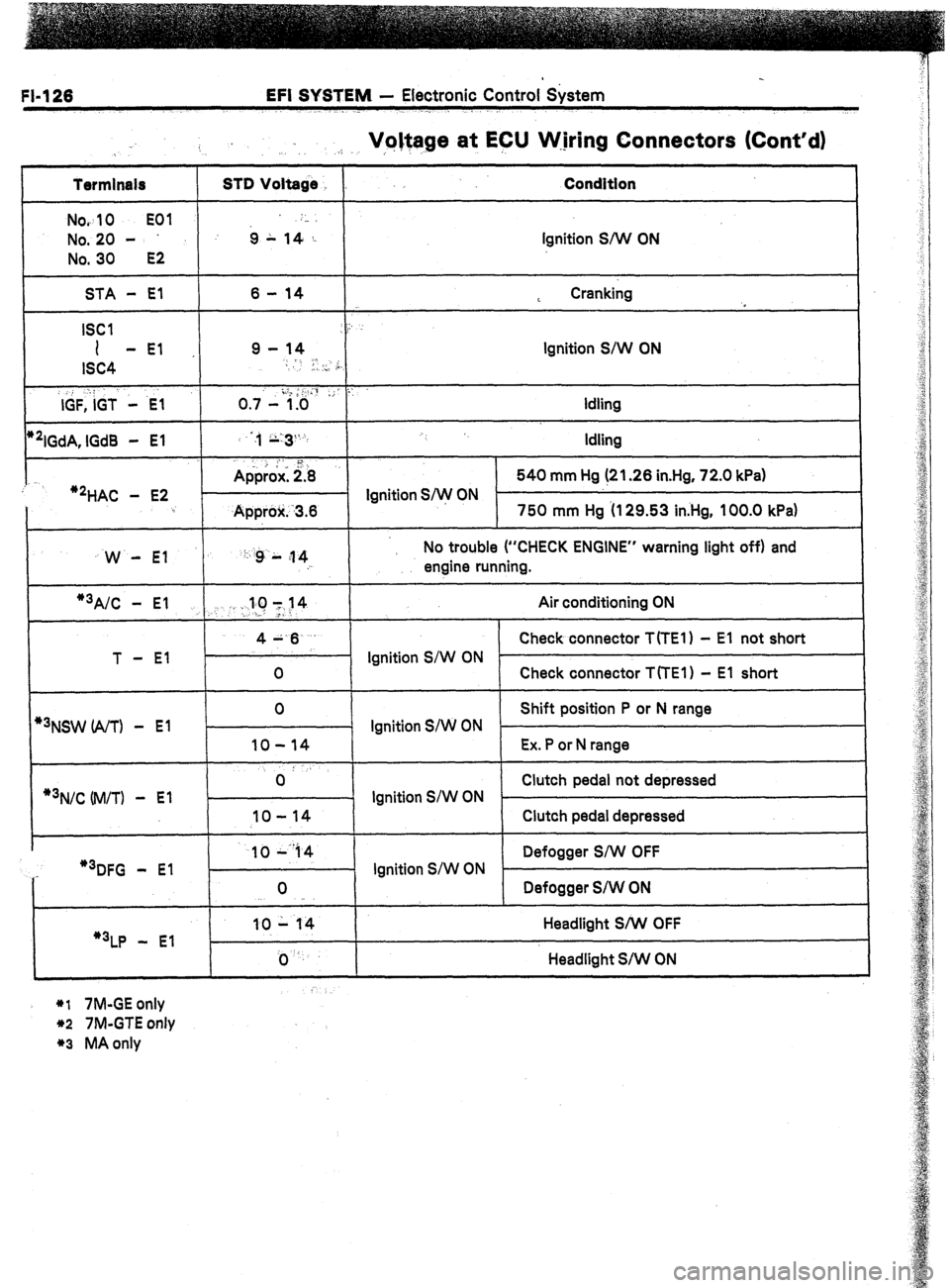
FI-126 EFI SYSTEM - Electronic Control &stem
Voltage at ECU W.jring Connectors (Cont’d)
.:. .I, ,,
Termlnals
Nov
10 EOI
No. 20 -
No. 30
E2
STD Voltage
6 L ,4-,: Condition
Ignition S/W ON
STA - El
ISCI
I -El
ISC4
,, : :
IGF, IGT - .E-1
*‘IGdA, lGd8 - El
:
‘2HAC - E2 6 - 14
9 - 14
-
I, .., ,i,
o .,.- i.;&& ,; ::
:,, ;;:3%
. . 1
Approx: 2.8
- Ignition S/w ON
Approlr. -3.6 L Cranking
,
Ignition S/W ON
Idling
Idling
540 mm Hg (21.26 in.Hg, 72.0 kPa)
750 mm Hg (I 29.53 in.Hg, 100.0 kPa)
W - El ‘: :g L ;I 4
: No trouble (“CHECK ENGINE” warning light off) and
engine running.
1
*3A/C - El .,. . :.llC 1~14 Air conditioning ON
>-
T - El 4A.6
Check connector T(TE1) - El not short
Ignition S/W ON
0 Check connector TfTEl) - El short
*3NSW (A/T) - El
*3N/C Uvl/TI -
El 0
Shift position P or N range
Ignition S/W ON
IO-14 Ex. P or N range
0: Clutch pedal not depressed
- Ignition S/W ON .
IO-14 Clutch pedal depressed
..-
I 1044 1 1 Defogger S/W OFF
I
“3DFG - El
“3LP - El 0
10 - 14
j) ‘. Ignition S/W ON
Defogger S/W ON
Headlight S/W OFF
Headlight S/W ON
*I 7M-GE only
*2 7M-GTE only
*3 MA only
Page 179 of 346
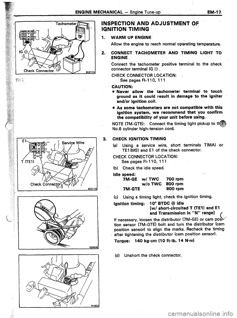
ENGINE MECHANICAL. - Engine Tune-up
EM-?1 7.
INS’PECTIOlil ‘AhiD ADJUSTMENT O:F .-
IGNITION TIMING
1. VriARiiA. UP ENGINE.
Allow the engine to. reach normal operating temperature.
2.
CbNNECT TACHOMETER AND TIMING LIGHT TO
ENGINE
Connect the tachometer positive terminal to the check
connector terminal IG 0 .
CHECK CONNECTOR LOCATION: .,
s See pages FI-110, 111
CAUTION:
l Never allow the tachometer terminal to touch
ground as it could result in damage to the igniter
and/or ignition coil.
, 4% 3.
EC21 18
s As some tachometers are not compatible with this
ignition system, we recommend that you confirm
the compatibility of your unit before using.
NOTE (7M-GTE): Connect the timing light pickup to t
No.6 cylinder high-tension cord.
CHECK IGNITION TIMING
(a) Using a service wire, short terminals T(MA) or
TEI (MS) and El of the check connector.
CHEC,K CCNNECTOR LOCATION.:
See pages FI- 1’10, 111
(b) Check the idle. speed.
Idle speed: /-
7M-GE w/ TWC 700 rpm
w/o TWC 800 rpm
7M-GTE 800 rpm
(c) Using a timing light, check the ignition timing.
Ignition timing: IO” BTDC @ idle
[w/ short-circuited T (TEl) and El
and Transmission in “N” range]
c,
If necessary, loosen the distributor (7M-GE) or cam posz-’
tion sensor (7M-GTE) bolt and turn the distributor (cam
position sensor) to align the marks. Recheck the timing
- after tightening the distributor (cam position sensor).
Torque: 140 kg-cm (10 ft-lb, 14 N-m)
(cl) Unshort the check connector.
Page 180 of 346
. .
EM-18 ENGINE MECHANICAL - Engine Tune-up
4. FURTHER CHECK IGNITION TIMING
Check that the ignition timing advances.
Ignition timing:
7M-GE ._ 10 -‘.13” BTDC @ idle
7M-GTE More than 12” BTDC @ idle
DISCONNECT TACHOMETER AND TIMING LIGHT
FROM ENGJNE
Page 212 of 346
3
EM-50 ENGINE MECHANICAL - Cylinder Head
1 (e) Check the’surface of the valve stem tip for wear.
If the valve stem tip is worn, regrind it with grinder or re-
place the valve if necessary.
CAUTION: D6 not grind off more than minimum over-
all length (See page EM-49).
12.
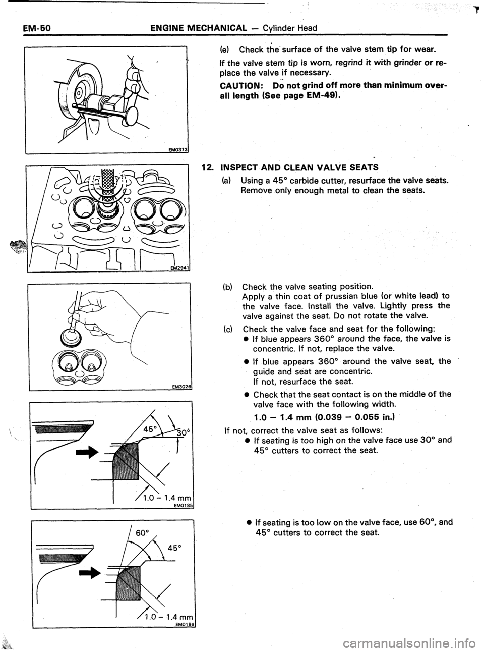
INSPECT AND CLEAN VALVE SEATS
(a) Using a 45” carbide cutter, resurface the valve seats.
Remove only enough metal to clean the seats.
EM3026
(b) Check the valve seating position.
Apply a thin coat of prussian blue (or white lead) to
the valve face. Install the valve. Lightly press the
valve against the seat. Do not rotate the valve.
(c) Check the valve face and seat for the following:
0 If blue appears 360” around the face, the valve is
concentric. If not, replace the valve.
0 If blue appears 360” around the valve seat, the
guide and seat are concentric.
If not, resurface the seat.
0 Check that the seat contact is on the middle of the
valve face with the following width.
1.0 - 1.4 mm (0.039 - 0.055 in.1
If not, correct the valve seat as follows:
0 If seating is too high on the valve face use 30” and
45” cutters to correct the seat.
l If seating is too low on the valve face, use 60°. and
45” cutters to correct the seat.
Page 230 of 346
EM-68 . ENGINE MECHANICAL - ,Cylinder Block
EM39
J ,32
(b) Remove the connecting rod cap nuts.
(c) Using a plastic-faced hammer, lightly tap the con-
necting rod bolts and lift off the connecting rod cap.
NOTE: Keep the lower bearing inserted with the con-
necting rod cap.
(d) Cover the connecting rod bolts with a short piece of
,hose to protect the crankshaft from damage.
(e) Clean the crank pin and bearing.
(f) Check the crank pin and bearing for. pitting and
scratches.
If the crank pin or bearing are damaged, replace the bear-
ings. If necessary, grind or replace the crankshaft.
(g) Lay a strip of Plastigage across the crank pin.
Page 287 of 346
-.
LUBRICATION SYSTEM
- Replacement.of Engine Oil and Oil Filter
L&.7*.
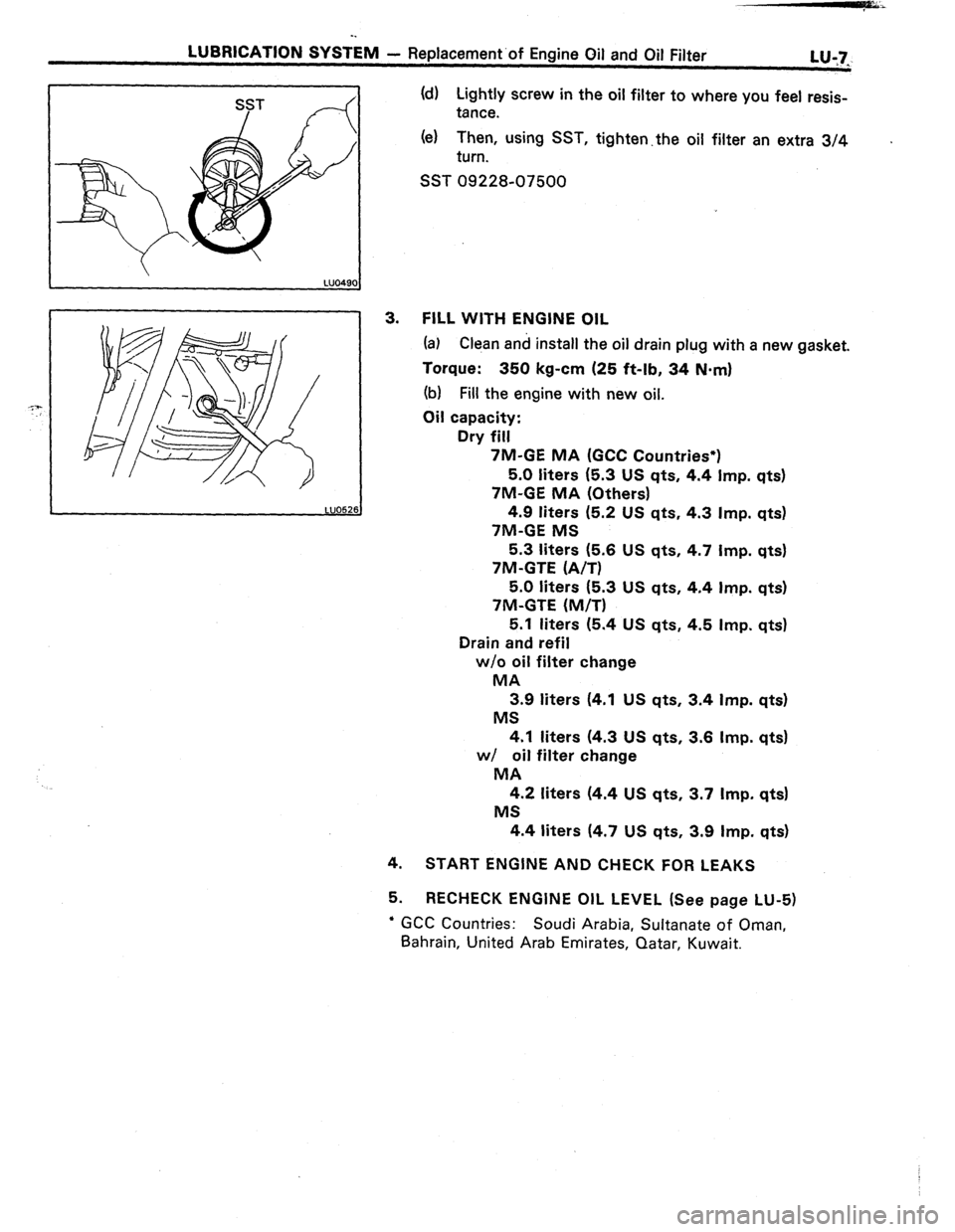
(d) Lightly screw in the oil filter to where you feel resis-
tance.
(el Then, using SST, tighten.the oil filter an extra 3/4
turn. .
SST 09228-07500
3. FILL WITH ENGINE OIL
(a) Clean and install the oil drain plug with a new gasket.
Torque: 350 kg-cm (25 ft-lb, 34 N.m)
(b) Fill the engine with new oil.
Oil capacity:
Dry fill
7M-GE MA (GCC Countries*)
5.0 liters (5.3 US qts, 4.4 Imp. qts)
‘/M-GE MA (Others)
4.9 liters (5.2 US qts, 4.3 Imp. qts)
7M-GE MS
5.3 liters (5.6 US qts, 4.7 Imp. qts)
7M-GTE (A/T)
5.0 liters (5.3 US qts, 4.4 Imp. qts)
7M-GTE (M/T)
5.1 liters (5.4 US qts, 4.5 Imp. qts)
Drain and refil
w/o oil filter change
MA
3.9 liters (4.1 US qts, 3.4 Imp. qts)
MS
4.1 liters (4.3 US qts, 3.6 Imp. qts)
w/ oil filter change
MA
4.2 liters (4.4 US qts, 3.7 Imp. qts)
MS
4.4 liters (4.7 US qts, 3.9 Imp. qts)
4.
START ENGINE AND CHECK FOR LEAKS
5. RECHECK ENGINE OIL LEVEL (See page LU-5)
’ GCC Countries: Soudi Arabia, Sultanate of Oman,
Bahrain, United Arab Emirates, Qatar, Kuwait.
Page 289 of 346
-.
LUBRICATION SYSTEM
- Replacement.of Engine Oil and Oil Filter
L&7_
4.
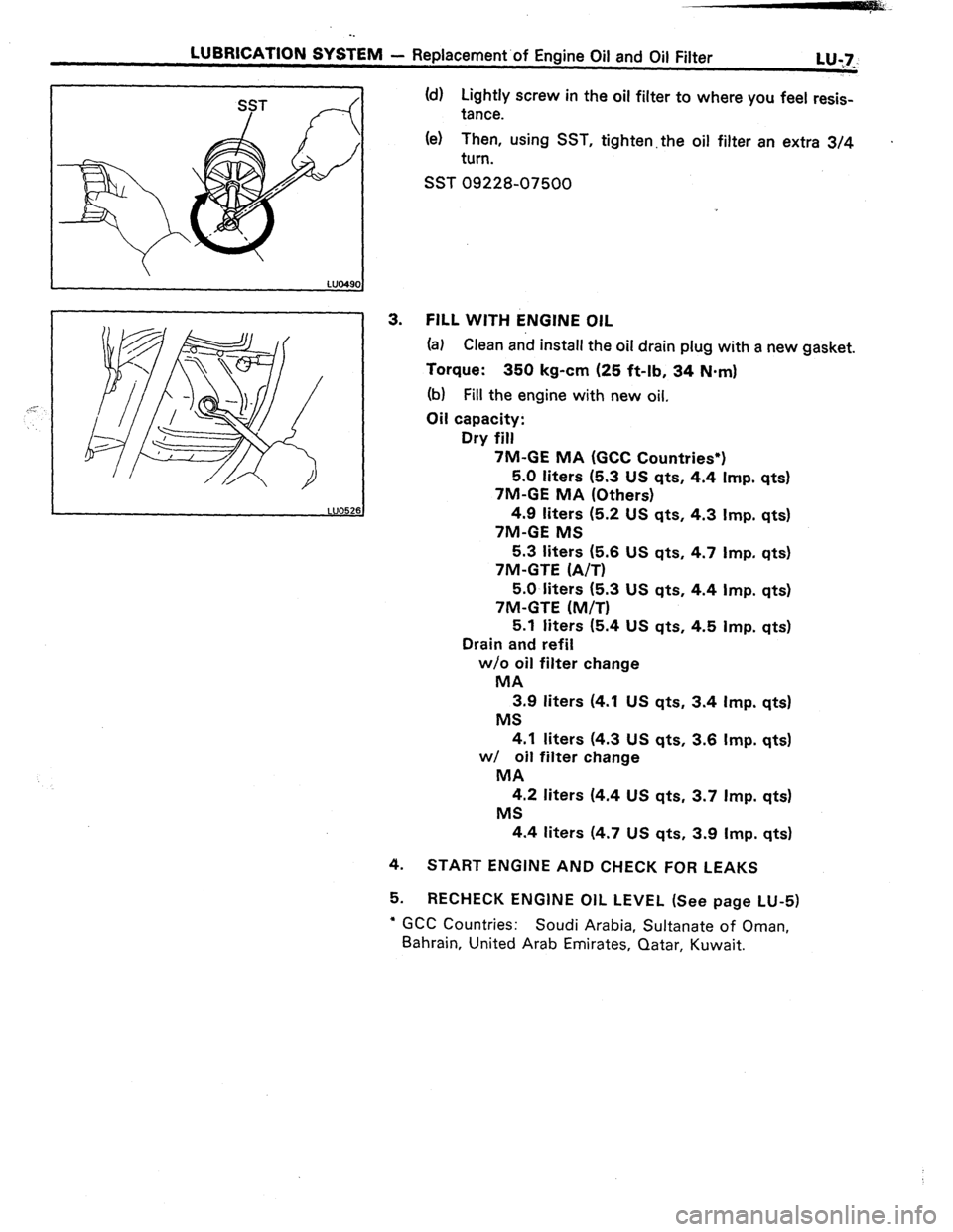
5. (d) Lightly screw in the oil filter to where you feel resis-
tance.
(e) Then, using SST, tighten. the oil filter an extra 3/4 .
turn.
SST 09228-07500
FILL WITH ENGINE OIL
(a) Clean and install the oil drain plug with a new gasket.
Torque: 350 kg-cm (25 ft-lb, 34 N-m)
(b) Fill the engine with new oil,
Oil capacity:
Dry fill
7M-GE MA (GCC Countries*)
5.0 liters (5.3 US qts, 4.4 Imp. qts)
7M-GE MA (Others)
4.9 liters (5.2 US qts, 4.3 Imp. qts)
7M-GE MS
5.3 liters (5.6 US qts, 4.7 Imp. qts)
7M-GTE (A/T)
5.0 liters (5.3 US qts, 4.4 Imp. qts)
7M-GTE (M/T)
5.1 liters (5.4 US qts, 4.5 Imp. qts)
Drain and refil
w/o oil filter change
MA
3.9 liters (4.1 US qts, 3.4 Imp. qts)
MS
4.1 liters (4.3 US qts, 3.6 Imp. qts)
w/ oil filter change
MA
4.2 liters (4.4 US qts, 3.7 Imp. qts)
MS
4.4 liters (4.7 US qts, 3.9 Imp. qtsl
START ENGINE AND CHECK FOR LEAKS
RECHECK ENGINE OIL LEVEL (See page LU-5)
l GCC Countries: Soudi Arabia, Sultanate of Oman,
Bahrain, United Arab Emirates, Qatar, Kuwait.
Page:
< prev 1-8 9-16 17-24