Page 61 of 346
Osc db-5 hus 4J -7.
EFI SYSTEM w
-. - Diagnosis System
FI-27
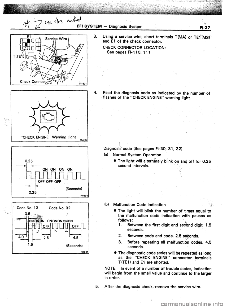
“CHECK ENGINE” Warning Light FlO29
Code No. 13 Code No. 32
(Seconds)
3. Using a service- wire, short terminals T(MA) or TEr(MS)
and El of the check connector.
CHECK CONNECTOR LOCATION:
See pages FI-110, 111
4. Read the diagnosis code as indicated by the number of
flashes of the “CHECK ENGINE” warning light.
Diagnosis. code (See pages FI-30, 31, 32)
(a) Normal System Operation
l The light will alternately blink on and off for 0.25
second intervals.
.)
(b) Malfunction Code Indication i
l The light will blink the number of times equal to
the malfunction code indication with pauses as-
follows:
1.
Between the first digit and se&d digit, 1.5
seconds.
2.
Between code and code, 2.5 se$onds.
3. Before repeating all malfunction codes, 4.5
seconds.
0 The diagnostic code series will be repeated as long
as the “CHECK ENGINE” connector terminals
T(TE1) and El are shorted.
NOTE: In event of a number of trouble codes, indication
will begin from the small value and continue to the larger
in
order.
After the diagnosis check, remove the service wire.
Page 62 of 346
EFI SYSTEM; Diagnosis System
S)
------) -.
I Fl281
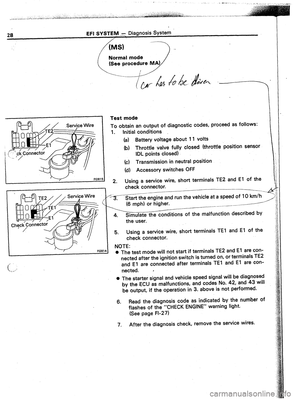
Test mode
i
To obtain an output of diagnostic codes, proceed as follows:
1. Initial conditions
(a) Battery voltage about 1 1 volts
(b) Throttle valve fully closed (throttle position sensor
IDL points closed)
(c) Transmission in neutral position
(d) Accessory switches OFF
2. Using a service wire, short terminals TE2 and El of the j
check connector.
-----.-q
*-heengine and run the vehicle at a speed of IO km/h I
(6 mph) or higher. __-- /---’
_ ___ _.--.--.
4. Simulate the conditions of the malfunction described by
the user.
5. Using a service wire, short terminals TEl and .El of the
check connector.
NOTE:
l The test mode will not start if terminals TE2 and El are con-
nected after the ignition switch is turned on, or terminals TE2
and El are connected after terminals TEI and El are con-
nected.
l
0 The starter signal and vehicle speed signal will be diagnosed
by the ECU as malfunctions, and codes No. 42, and 43 will
be output, if the operation in 3. above is not performed.
6. Read the diagnosis code as indicated by the number of
flashes of the “CHECK ENGINE” warning light.
(See page FI-27)
7. After the diagnosis check, remove the service wires.
Page 63 of 346
EFI SYSTEM - Diagnosis System FI-29
MS EFI 15iA
LHD
EFI 15A
EFI 15A
R16C
FI26:
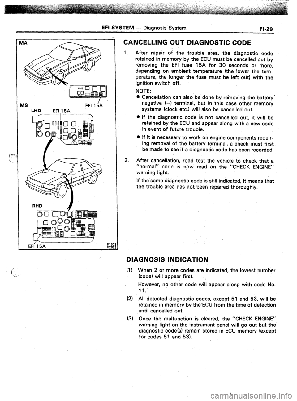
CANCELLING OUT DIAGNOSTIC CODE
1.
2. After repair of the trouble area, the diagnostic code
retained in memory by the ECU must be cancelled out by
removing the EFI fuse 15A for 30 seconds or more,
depending on ambient temperature (the lower the tem-
perature, the longer the fuse must be left out) with the
ignition switch off.
NOTE:
l Cancellation can also be done by removing the battery”
negative (-1 terminal, but in this case other memory
systems (clock etc.) will also be cancelled out.
l If the diagnostic code is not cancelled out, it will be
retained by the ECU and appear along with a new code
in event of future trouble.
l If it is necessary to work on engine components requir-
ing removal of the battery terminal, a check must first
be made to see if a diagnostic code has been recorded.
After cancellation, road test the vehicle to check that a
“normal” code is now read on the “CHECK ENGINE”
warning light.
If the same diagnostic code is still indicated, it means that
the trouble area has not been repaired thoroughly.
DIAGNOSIS INDICATION
(I) When 2 or more codes are indicated, the lowest number
(code) will appear first.
However, no other code will appear along with code No.
11.
(2) All detected diagnostic codes, except 51 and 53, will be
retained in memory by the ECU from the time of detection
until cancelled out.
(3) Once the malfunction is cleared, the “CHECK ENGINE”
warning light on the instrument panel will go out but the
diagnostic code(s) remain stored in ECU memory (except
for codes 51 and 53).
Page 67 of 346
EFI SYSTEM
- Diagnosis System
FI-33
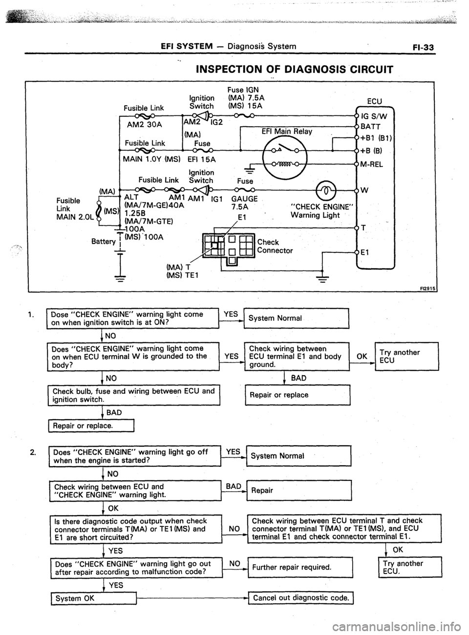
INSPECTION OF DIAGNOSIS .ClRCUlT
._
Fuse IGN
“CHECK ENGINE”
Fl291
1.
I Dose “CHECK ENGINE” warning light come
on when ignition switch is at ON?
l-l YES System Normal
Does “CHECK ENGINE” warning light come Check wiring between
on when ECU terminal W is grounded to the
YES ECU terminal El and body OK Try another
body? - ground. __c ECU
+NO
Check bulb, fuse and wiring between ECU and
ignition switch. + SAD
Repair or replace
Does “CHECK ENGINE” warning light go off
when the engine is started? YES
. System Normal
NO
Check wiring between ECU and
“CHECK ENGINE” warning light.
1 OK
Is there diagnostic code output when check
connector terminals T(MA) or TEl (MS) and
El are short circuited? t
Check wiring between ECU terminal T and check
NO connector terminal T(MA) or TEl (MS), and ECU
* terminal El and check connector terminal El.
I I
I I
YES
Does “CHECK ENGINE” warning light go out NO
after repair according to malfunction code? ) Further repair required.
&
System OK Cancel out diagnostic code.
Page 71 of 346
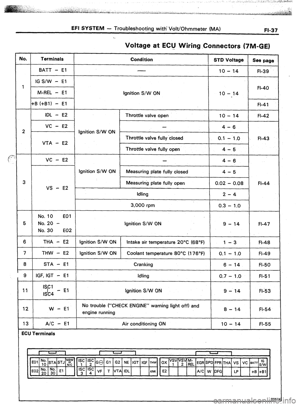
EFI SYSTEM - Troubleshooting with’ Volt/Ohmmeter (MA) FI-37
Voltage at EClJ Wiring .Connectors (TIM-GE)
IO. Terminals
Condition STD Voltage
See page
BATT - El
10 - 14 FI-39
IG S/W - El
1 FI-40
M-REL - El
Ignition S/W ON 10 - 14
+B (+Bl) - El FI-41
IDL - E2 Throttle valve open 10 - 14 FI-42
vc - E2 -
4-6
2 Ignition S/W ON -
Throttle valve fully ‘closed 0.1
- 1.0 FI-43
VTA - E2
Throttle valve fully open 4-5
VC - E2 4-6
Ignition S/W ON
Measuring plate fully closed 4-5
3 Measuring plate fully open 0.02 - 0.08 FI-44
VS - E2
Idling 2-4
3,000 rpm 0.3 - 1.0
No. 10 EOI
5 No. 20 - Ignition S/W ON 9 - 14 FI-47
No. 30 E02
6 THA - E2 Ignition S/W ON Intake air temperature 20°C (68°F) 1 -3 FI-48
7 THW - E2 Ignition S/W ON Coolant temperature 80°C II 76’F) 0.1 - 1 .O
FI-49
8 STA - El Cranking
6 - 14 FI-50
9 IGF, IGT - El Idling
0.7 - 1.0 FI-5 1
11 ISCI
I&4 - El Ignition S/W ON 9-14 Fl-53
12 W - El No trouble (“CHECK ENGINE” warning light off) and
engine running 8 - 14 FI-54
13 A/C - El Air conditioning ON IO - 14 FI-55
ECU Terminals
‘~,~] E2 4
/UC W:G up +S :,:I
N:y Is’ Is’ GO Gl G2 NE IGT IGF THW OX “s, “;“riL EGR SPD FPR THA VS VC BATT IG
F1057
Page 72 of 346
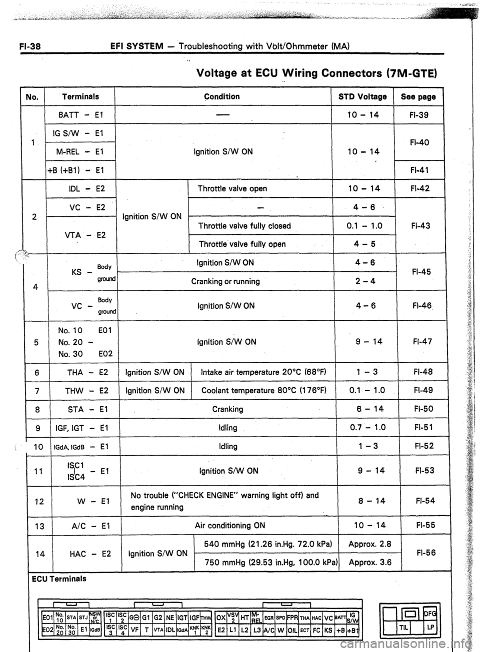
EFI SYSTEM - Troubleshooting with Volt/Ohmmeter (MA)
. .
Voltage at ECU Wiring Connectors (7M-GTE)
No. Terminals
Condition STD Voltage Sea page
BATT - El 10 - 14
FI-39
IG S/W - El
1
FI-40
M-REL - El Ignition S/W ON 10 - 14
+B (+Bl) - El
FI-41
*
IDL - E2 Throttle valve open 10 - 14 FI-42
VC - E2 4-6.
2 . Ignition S/W ON
Throttle valve fully closed 0.1 - 1.0 FI-43
VTA - E2
Throttle valve fully open 4-5
i
KS - Body Ignition S/W ON 4-6
FI-45
gnMid
4 Cranking or running 2-4
vc - Body
Ignition S/W ON 4-6
groulld Fl-46.
No. 10 EOl
5 No. 20 - Ignition S;W CN 9 - 14 Fl-47
No. 30 E02
6 THA - E2 Ignition S/W ON Intake air temperature 20°C (68°F) 1 -3 FI-48
7 THW - E2 Ignition S/W ON Coolant temperature 80°C (176°F) 0.1 - 1 .O FI-49
8 STA - El Cranking 6-14 FI-50
9 IGF, IGT - El Idling 0.7 - 1.0 FI-5 1
10 IGdA, IGdB - El Idling 1-3 FI-52
11 I Cl
7 9 - 14 FI-53
ISC4 - El Ignition S/W ON
12 W - El No trouble (“CHECK ENGINE” warning light off) and
engine running 8 - 14 FI-54
13 A/C - El
14 HAC - E2 Air conditioning ON 10 - 14
FI-55
540 mmHg (21.26 in.Hg. 72.0 kPa) Approx. 2.8
Ignition S/W ON FI-56
750 mmHg (29.53 in.Hg, 100.0 kPa) Approx. 3.6
ECU Terminals
I U 1 I -
I
1
‘yc ‘;c GQ Gl G2 NE IGT IGF ~Hln, OX “;’ HT r;,
EGR SPD FPR THA HAC VC ‘JAn& 0 DF
‘;’ ‘sd: VF T VTA IDL
WA ““1” K;K E2 Ll L2 L3 NC W OIL ECT FC KS +B +Bl m
TIL LP
Page 88 of 346
EFI SYSTEM - Troub!eshoo$ng with Volt/Ohmmeter (MA)
. .
JO. Terminals
12 W - El Trouble
No voltage Condition
Nq @uble, (“CHECK” engine warning
light off) and engine running STD Voltage
s-14v
FUSE
GAUGE 7.5A
i
f “CHECK ENGINE”
Wahiing Light
Combination Mete W
El
FlO7
Joltmeter
EL v “_
Fl1251
1
Voltmeter
FH25C
. .
~0 There is no voltage between ECU terminals W and El.
(Idlin$
,
.
I 0
Check that there is voltage between ECU terminal W and
I
hod
Q;
0 Check wiring between ECU terminal El and body
Check GAUGE fuse (7.5A) and “CHECK
ENGINE” warning light.
I I
I Repair or replace.
I
1
Check wiring between ECU terminal BAD
*
W and fuse. Repair or replace.
I I
1 I
Page 93 of 346
EFI SYSTEM - Ttpbleshooting with Volt/Ohmmeter (MS)
FL59
IO.
I Terminals
BATT - El
IG S/W - El
M-REL - El
2P-
I UTA - E2
3
US - E2
THA - E2
THW - E2
.B / IGF, IGT - El
9 ISCI
lSC4 - El
10
I W - El
ECU Terminals
Voltage at ECU Wiring Connectors
Condition STD Voltage ’
10 - 14
ignition S/W ON
10 - 14
Throttle valve open 10 - 14
4-6
Ignition S/W ON .
Throttle valve fully closed 0.1 - 1.0
Throttle valve fully open
4-5
4-6
Ignition S/W ON Measuring plate fully closed
4-5
Measuring plate fully open
0.02 - 0.08
Idling 2-4
3,000 rpm 0.3 - 1 .o
Ignition S/W ON 9
- 14 FI-66
Ignition S/W ON Intake air temperature 20°C (68°F) 1
-3
Ignition S/W ON
Coolant temperature 80°C (176°F) 0.1 - 1.0
Cranking
6 - 14
Idling 0.7 - 1.0
Ignition S/W ON
9 - 14
No trouble (“CHECK-ENGINE” warning light off) and
engine running 8 - 14 See page
FI-60
FI-6 1
FI-62
FI-63
FI-64
Fl-65
Fl-6.7
FI-68
FI-69
Fl-70
FI-7 1
Fl;72