Page 169 of 346
ENGINE MECHANICAL 2 Engine Tune-up
. . EM-7
ENGINE TUNE-UP
INSPECTlOi OF ENGINE COOLANT
(See page CO-51
INSPECTION OF ENGINE OIL
(See page LU-5)
t MA02931
INSPECTION Oi’AIR FILTER
(a) Visually check that the air cleaner element is not
excessively dirty, damaged or oily.
(b) Clean the element with compr&sed air.
First blow from back side thoroughly. Then blow off
the front side of the element.
INSPECTION OF BATTERY
(See page CH-3)
INSPECTION OF HIGH-TENSION CORDS
(See pages IG-6, 13)
INSPECTION OF SPARK PLUGS
(See pages 19-7 to 9)
INSPECTION OF DRIVE BELT
(See page CH-41
Page 224 of 346

EM-62
ENGINE MECHANICAL + Cylinder Head
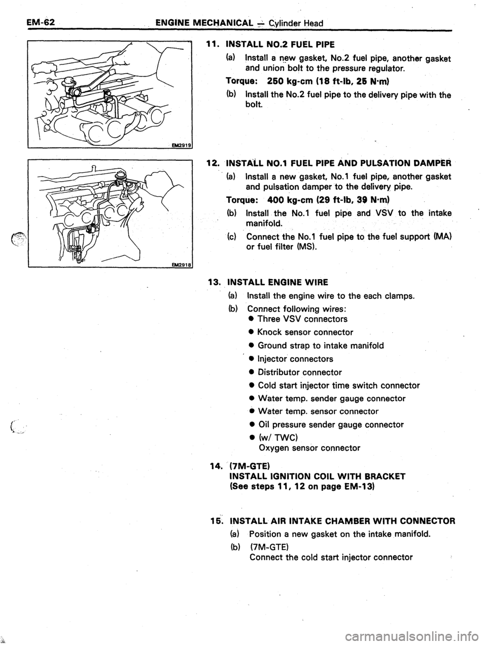
11. INSTALL NO.2 FUEL PIPE
(a) Install a r-13~ gasket, No.2 fuel pipe, another gasket
and union bolt to the pressure regulator.
Torque: 2bO kg-cm (18 ft-lb, 28 N-m)
(b) Install the No.2 fuel pipe to the delivery pipe with the
bolt.
12. INSTALL ~0.1 FUEL PIPE AND PULSATION DAMP&~
(a) Install a new gasket, No.1 fuel pipe, another gasket
and pulsation damper to the delivery pipe.
Torque: 400 kg-cm (29 ft-lb, 39 N*m)
(b) Install the No.1 fuel pipe and VSV to the intake
manifold.
(c) Connect the No.1 fuel pipe to the fuel support (MA)
or fuel filter (MS).
13. INSTALL ENGINE WIRE
(a) Install the engine wire to the each clamps.
(b) Connect following wires:
0 Three VSV connectors
0 Knock sensor connector
0 Ground strap to intake manifold
l Injector connectors
l Distributor connector
l Cold start injector time switch connector
0 Water temp. sender gauge connector
l Water temp. sensor connector
l Oil pressure sender gauge connector
l (w/ nvc)
Oxygen sensor connector
14. (7M-GTE)
INSTALL IGNITION COIL WITH BRACKET
(See steps 11, 12 on page EM-1 31
15. INSTALL AIR INTAKE CHAMBER WITH CONNECTOR
(a) Position a new gasket on the intake manifold.
(b) (7M-GTE)
Connect the cold start injector connector
Page 228 of 346

EM-66 ENGINE MECHANICAL - Cylinder Block
_. DISASSEMBLY OF CYLINDER BLOCK
(See page EM-651
1. REMOVE FLYWHEEL OR DRIVE PLATE AND REAR
END PLATE
2. INSTALL ENGINE STAND FOR DISASSEMBLY
3. REMOVE TIMING BELT
(See steps 2 to 8 and 10 to 18 on pages EM-28 to 31)
4. REMOVE CYLINDER HEAD .I
(See steps 1 to 15 and 18 on pages EM-39 to 43)
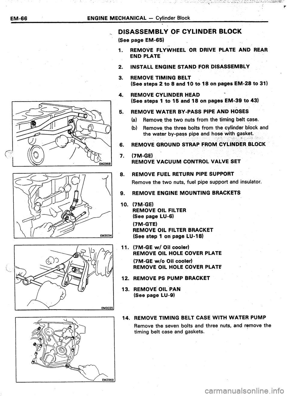
5. REMOVE WATER BY-PASS PIPE AND H&ES
(a) Remove. the two nuts from the timing belt case.
(b) Remove.the three bolts from the cylinder block and
the water by-pass pipe and hose with gasket.
__” r
6. REMOVE GROUND STRAP FROlV&Y~l~tiER BLOkK
7. (7M-GE) -
REMOVE VACUUM CONTROL VALVE SET
8. REMOVE FUEL RETURN PIPE SUPPORT
Remove the two nuts, fuel pipe support and insulator.
9. REMOVE ENGINE MOUNTING BRACKETS
10. (‘IM-GE)
REMOVE OIL FILTER
(See page LU-6)
(7M-GTE)
REMOVE OIL FILTER BRACKET
(See step 1 on page LU-18)
11.
12.
13. (7M-GE w/ C#l cooler)
REMOVE OIL HOLE COVER PLATE
(7M-GE w/o Oil cooler)
REMOVE OIL HOLE COVER PLATE
REMOVE PS PUMP BRACKET
REMOVE OIL.PAN
(See page LU-9)
14. REMOVE TIMING BELT CASE WITH WATER PUMP
Remove the seven bolts and three nuts, and r!move the
timing belt case and gaskets.
Page 254 of 346

EM-92 _. ENGINE MECHANICAL +’ Cylinder Block
-..
: .
;,,
“.’
‘i4. (7M-GE w/ Oil Cooler)
INSTALL Oil.. REGULATOR
Install a new gasket and oil regulator with. the two bolts.
(7M-GE w/o Oil Cooler and.7M-GTE)
INSTALL OIL HOLE COVER PLATE
Install a new gasket and oil hole cover plate with the two .
bolts.
15. (7M-GE)
INSTALL NEW OIL FILTER
(See page LU-6)
16. INSTALL ENGlNE MOUNTING BRACKETS
17. INSTALL FUEL RETURN PIPE SUPPORT
Install a new insulator and fuel pipe support with the two
nuts. :
Torque: 130 kg-cm (69 ft-lb, ‘1.3 N&l
18. (7M-GE)
INSTALL VACUUM CONTROL VALVE SET
19. INSTALL GROUND STRAP TO CYLI’NDER BLOCK
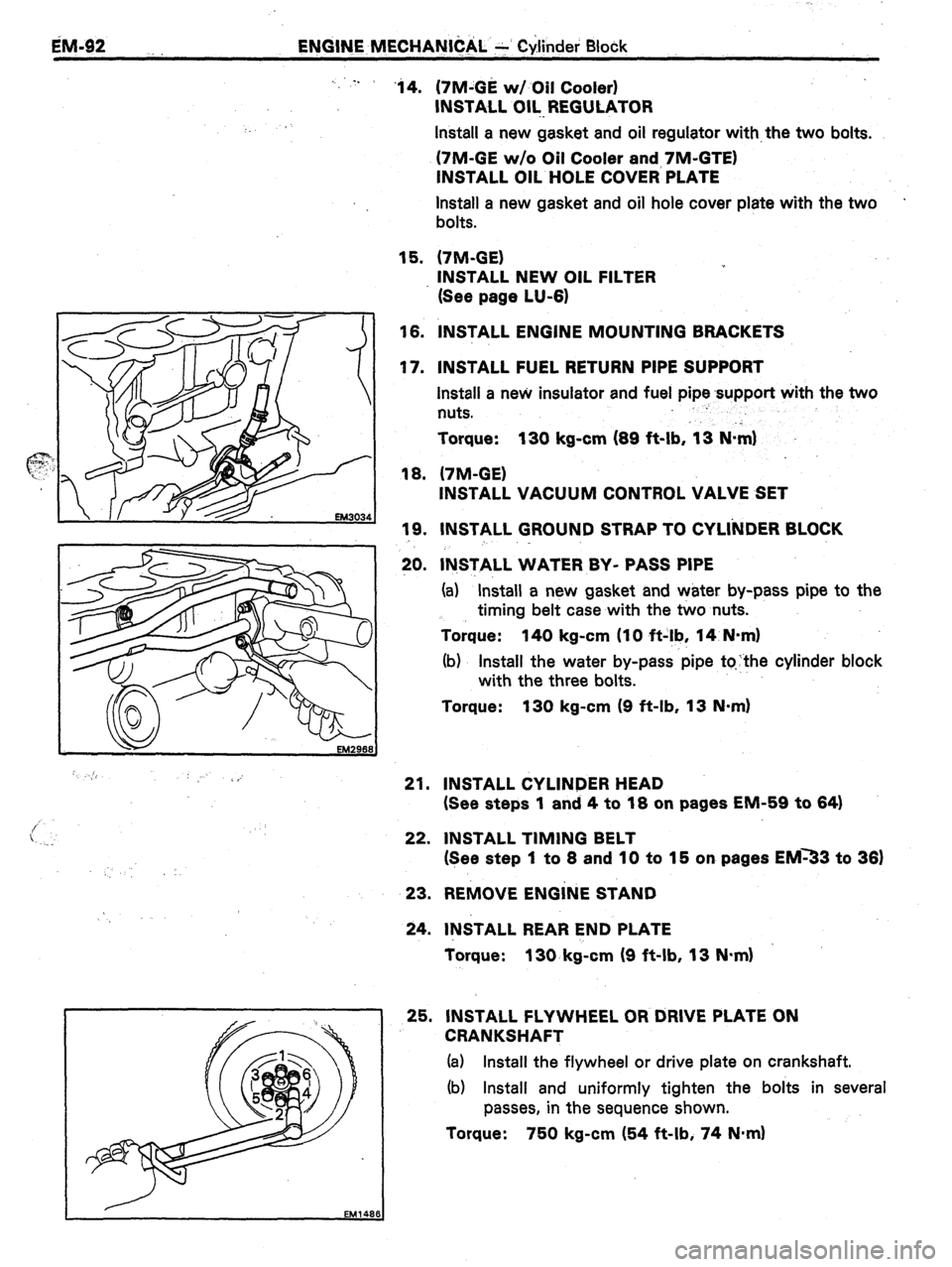
20. lN,STALL WATER BY- PASS PIPE
(a) “Install a new gasket and water by-pass pipe to the
timing belt case with the two nuts.
Torque: 140 kg-cm (IO ft-!b, 14 N-m)
(b) Install the water by-pass pipe tqthe cylinder block
with the three bolts.
Torque: 130 kg-cm (9 ft-lb, 13 N-m)
21. INSTALL CYLINDER HEAD
(See steps 1 and 4 to 18 on pages EM-59 to 64)
22. INSTALL TIMING BELT
(See step 1 to 8 and 10 to 15 on pages EM33 to 36)
23. REMOVE ENGiNE STAND
24. INSTALL REAR END PLATE
Torque: 130. kg-cm (9 ft-lb, 13 N.m)
25. INSTALL FLYWHEEL OR DRIVE PLATE ON
CRANKSHAFT
(a) Install the flywheel or drive plate on crankshaft.
(b) Install and uniformly tighten the bolts in several
passes, in the sequence shown.
Torque: 750 kg-cm (54 ft-lb, 74 N*m)
Page 282 of 346
-.
. .
..,I -_
LUBRICATION SYSTEM: . . I-
Page
DESCRIPTION . . ..*.*.........*......*........
LU-2
TROUBLESHOOTING ..I....*........*.‘....... b-4
OIL PRESSURE CHECK . . , . . . . . .
l . . . . . . , . . . . . . . ‘LU-5
REPLACEMENT OF ENGINE OIL
AND OIL FILTER I*......**.~.....~..,,,,..,.
LU-6
OIL PUMP *I...~.......~.~.,,,...~...~‘,,...,.
LU-6
OIL COOLER AND OIL PRESSURE
REGULATOR (7M-GE) . . . . . . . . . . . . . . . . . . . . . . . LU-15
OIL COOLER AND OIL PRESSURE
REGULATOR (7M-GTE) . . . . . . . . . . . . . . a. . . . . . LU-16
Page 283 of 346
LU-2
-4UBRlCATlON SYSTEM - Description
DESCRIPTION --
A fully pressurized, fully filtered lubrication system has been adopted for this engine.
7M-GE (MS) 7M-GE (MA)
Oil Co&x
7M-GTE (A/T)
Oil Choler
( VALVE GUIDES -
.---- PISTONS
t
.- - - - CONNECTING
RODS
t
.----
{ CRANKSHAFT 1
I *OIL FILTER BRACKET
+---+ RELIEF VALVE 1
1 RELIEF VALVE
I
I I
OIL PUMP
t
I OIL STRAINER
t
OIL PAN l 7M-GTE only
Page 284 of 346

LUBRICATION SYSTEM - Description
.,LU-3
A pressure feeding lubrication system has been
adopted to supply oil to the moving parts of this
engine. The lubrication system consists of an oil
pan, oil pump, oil filter and other external parts
which supply oil to the moving parts in the engine
block. The oil circuit is shown in the illustration at
the top of the previous page. Oil from the oil pan is
pumped up by the oil pump. After it passes
through the oil filter, it is fed through the various
oil holes in the crankshaft and cylinder block. After
passing through the cylinder block and performing
its lubricating function, the oil is returned by gra-
vity to the oil pan. A dipstick on the side of the
cylinder block is provided to check the oil level.
OIL PUMP
The oil pump pumps up oil from the oil pan and
sends it under pressure to the various parts of the
engine. An oil strainer is mounted in front of the
inlet to the oil pump. The oil pump itself is a gear
pump, which uses a drive gear and driven gear
inside the pump body. When the drive gear
rotates, the driven gear rotates in the opposite
direction. When the gear teeth disengage oil is
drak n in, and when the gear teeth engage oil is
discharged.
OIL PRESSURE REGULATOR
At high engine speeds, the engine oil supplied
bY thr oil pump exceeds the capacity of the engine
10 utiiize it.
For that reason, the oil pressure regula-
tor i ,>rks to prevent an oversupply of oil. During
norm.tl oil
supply, a coil spring and valve keep the
bYPcls:s closed, but when too much oil is being fed,
the I’tt’essure becomes extremely high, overpower-
9 the force of the spring and opening the valves.
This ;:ilows the excess oil to flow through the
Yalvtj :snd return to the oil pan. Olii FILTER
The oil filter is a full flow type filter with a built-
in paper filter element. Particles of :metal ‘from
wear, a&born dirt, carbon and other impurities can ’
get in the oil during use and could cause acceler-
ated wear or siezing if allowed to circulate through
the engine. The oil filter, integrated into the oil line,
removes these impurities as the oil passes through
it. The filter is mounted outside the engine to
simplify replacement of the filter element. A relief
valve is also included ahead of the filter element to
relieve the high oil pressure in case the filter ele-
ment becomes clogged with impurities. The relief
valve opens when the oil pressure overpowers the
force of the spring. Oil passing through the relief
valve bypasses the oil filter and flows directly into
the main oil hole in the engine.
Page 285 of 346
LU-4 LUBRICATION SYSTEM - Troubleshooting
Problem
Oil leakage
Low oil pressure
High oil pressure
TROUBilESHOOTlNG
Possible cause
Cylinder head, cylinder block or oil pump
body damaged or cracked
Oil seal faulty
Gasket faulty
Oil leakage
Relief valve faulty
Oil pump faulty
Engine oil poor quality
Crankshaft bearing faulty
Connecting rod bearing faulty
Oil filter clogged
Relief valve faulty Remedy
Repair as necessary
Replace oil seal I
Replace gasket
Repair as necessary
Repair relief valve
Repair oil pump
Replace engine oil
Replace bearing
Replace bearing
Replace oil filter
Repair relief valve Page
EM-84
LU-8
W-8 ~