1987 TOYOTA CELICA fuse
[x] Cancel search: fusePage 7 of 346
INTRODUCTION - General Repair Instructions
IN-S
(b) Recoating of Precoated Parts
(1) Clean off the old adhesive from the part’s
threads.
(2) Dry with compressed air.
(3) Apply the specified seal lock adhesive to the
part’s threads.
(c) Precoated parts are indicated in the component
illustrations by the “*” symbol.
7. When necessary, use a sealer or gaskets to prevent leaks.
8. Carefully observe all specifications for bolt torques.
Always use a torque wrench.
9. Use of special service tools (SST) and special service
materials (SSM) may be required, depending on the nature
of the repair. Be sure to use SST and SSM where specified
and follow the proper work procedure. A list of SST and
SSM can be found at the back of this manual.
10. When replacing fuses, be sure the new fuse is the correct
amperage. DO NOT exceed the fuse amp rating or use one
of a lower rating.
11. Care must be taken when jacking up and supporting the
vehicle. Be sure to lift and support the vehicle at the
proper locations.
(a) If the vehicle is to be jacked up only at the front or
rear end, be sure to block the wheels in order to
ensure safety.
(b) After the vehicle is jacked up, be sure to support it on
stands. It is extremely dangerous to do any work on
the vehicle raised on a jack alone, even for a small job
that can be finished quickly.
WRONG
CORRECT 12. Observe the following precautions to avoid damaging the
parts:
(a) Do not open the cover or the case of the ECU unless
absolutely necessary. (If the IC terminals are touched,
the IC may be destroyed by static electricity.)
(b) Be careful not to drop electrical components, such as
sensors or relays. If they are dropped on a hard floor,
they should be replaced and not reused.
(c) When disconnecting vacuum hoses, pull on the end
of the hose, not the middle.
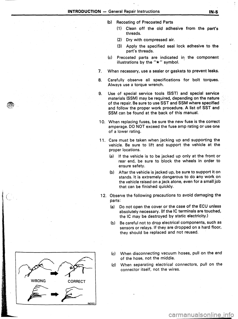
(d) When separating electrical connectors, pull on the
connector itself, not the wires.
Page 9 of 346
CH-2 CHARGING SY&EM - Precautions, Troubleshooting
._
: PRECAUTIONS
1. Check that the battery cables are connected to the
correct terminals.
2. Disconnect the battery cables when the battery is
given a quick charge.
3. Do not perform tests with a high voltage insulation
resistance tester.
4. Never disconnect the battery while the engine is run-
ning.
Discharge warning
light does not light
with ignition ON and
engine not ‘running
Problem
Discharge warning
light does not go out
with engine running
(battery requires fre-
quent recharging
Possible cause
Fuse blown
Light burned out
Wiring connection loose
IC regulator faulty
TROUBLESHOOTING
Remedy
Check “CHG” and
“IGN” fuses
Replace light
Tighten loose connections
Replace IC regulator
Drive belt loose or worn
Battery cables loose, corroded or worn
Fuse blown
Fusible link blown
IC regulator or alternator faulty
Wiring faulty Adjust or replace drive belt
Repair or replace cables
Check “ENG” fuse
Replace fusible link
Check charging system
Repair wiring
Page
CH-7
CH-4
CH-3
Page 10 of 346
:usible
.ink
4LT
MA/
‘M-GE)
,258 Ignition Switch
Fuse
AM2 -0p IG2 (MA) 15~4
c (MS) 7.5A
Fusible
Link
AM2 30A
:usible
-ink
I (MA)
I/IAIN 2.OL (MS)
T Battery
P
/
CHG 7.5 A
I
i
8
I I .
i
m
Alternator
1 ON-VEHICLE INSPECTION
1.
tieI
fel
i 002
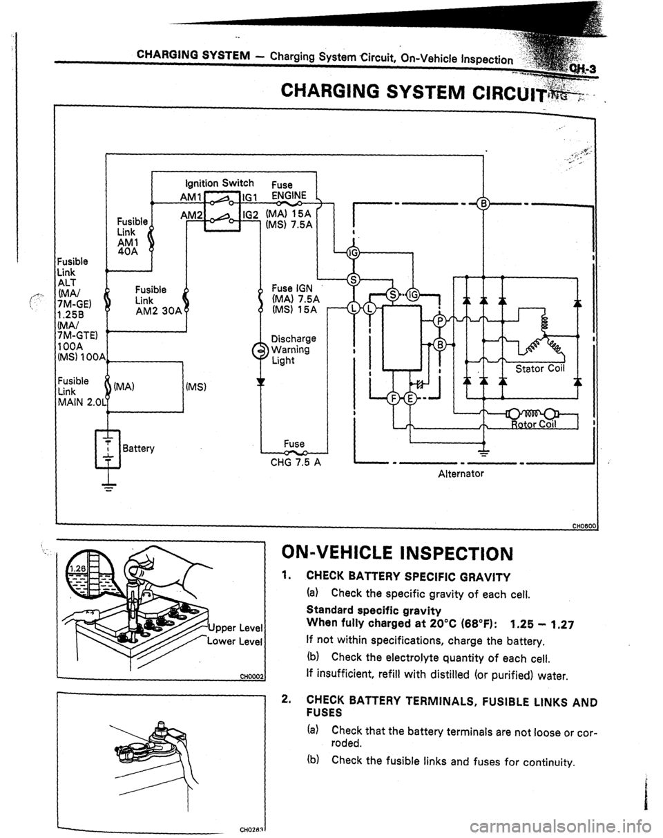
CHECK BATTERY SPECIFIC GRAVITY
(a) Check the specific gravity of each cell.
Standard specific gravity
When fully charged at 20°C (66°F):
1.25 - 1.27
If not within specifications, charge the battery.
(b) Check the electro!yte quantity of each cell.
If insufficient, refill with distilled (or purified) water.
’ 2. CHECK BATTERY TERMINALS, FUSIBLE LINKS AND
FUSES
(a) Check that the battery terminals are not loose or cor-
roded.
(b) Check the fusible links and fuses for continuity.
c
CHOZRRI
Page 46 of 346
1-12 EFI SYSTEM - Troubleshooting’
FlO48
TROUBLESH~~TI~~G
. .
TROUBLESHOOTING HlhJTS
1. Engine troubles are usually not caused by the EFI system.
When troubleshooting, always first check the condition of
the other systems.
(a) Electronic source
0 Battery
0 Fusible links
0 Fuses
(b) Body ground
(cl Fuel supply
0 Fuel leakage
0 Fuel filter
0 Fuel pump
(d) Ignition system
0 Spark plug
0 High-tension cord
l Distributor (7M-GE) or cam position sensor (7M-
GTE)
0 Igniter and ignition coil
(e) Air induction system
0 Vacuum leaks
(f) Emission control system
0 PCV system
0 EGR system (w/ EGR)
(g) Others
l Ignition timing (ESA system)
0 Idle speed (ISC system)
-r
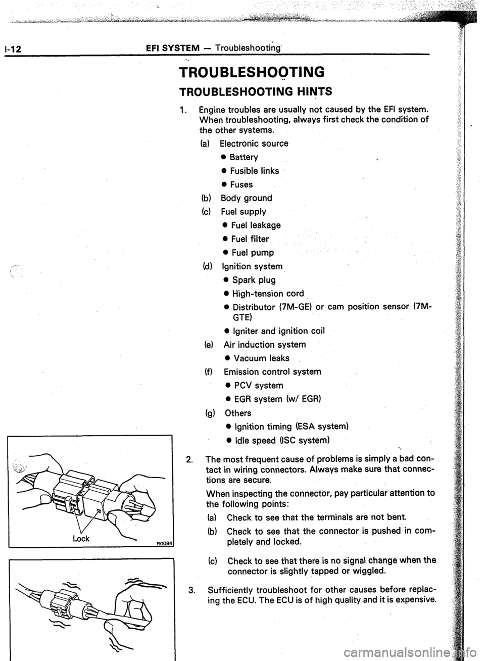
2. The most frequent cause of problems is simply a bad don-
tact in wiring connectors. Always make sure that connec-
tions are secure.
When inspecting the connector, pay particular attention to
the following points:
(a) Check to see that the terminals are not bent.
(b) Check to see that the connector is pushed in com-
pletely and locked.
(c) Check to see that there is no signal change when the
connector is slightly tapped or wiggled.
3. Sufficiently troubleshoot for other causes before replac-
ing the ECU. The ECU is of high quality and it is expensive.
Page 49 of 346
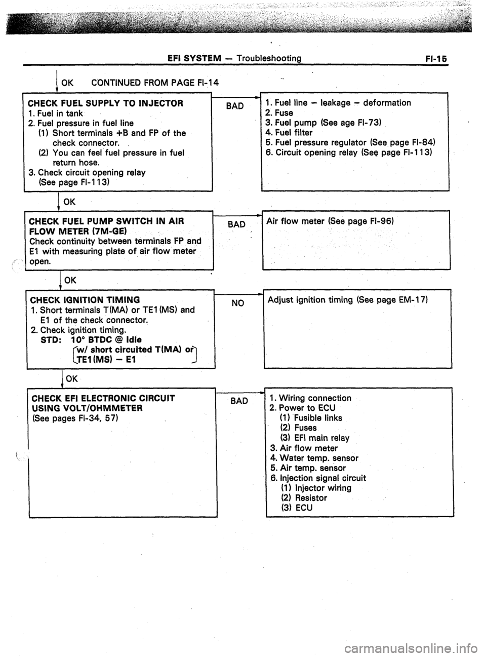
EFI SYSTEM - Troubleshooting
FI-1 E
CONTINUED FROM PAGE FI-14 ._
CHECK FUEL SUPPLY TO INJECTOR
1. Fuel in tank
2. Fuel pressure in fuel line
(1) Short terminals +B and FP of the
check connector.
(2) You can feel fuel pressure in fuel
return hose. BAD 1. Fuel line - leakage - deformation
2. Fuse
3. Fuel pump (See age FI-73)
4. Fuel filter
5. Fuel pressure regulator (See. page FI-84)
6. Circuit opening relay (See page FI-1 13)
3. Check circuit opening relay
(See page FI-1 13)
OK
CHECK FUEL PUMP SWITCH IN AIR
FLOW METER (7M-GE)
Check continuity between terminals FP and
El with measuring plate of,air flow meter
,,’
open.
L
I BAD c
Air flow meter (See page FL96)
I OK
CHECK IGNITION TIMING
1. Short terminals T(MA) or TEl (MS) and
El of the check connector.
2. Check ignition timing.
STD: 10’ BTDC @ Idle
short circuited TIMA) or
3
I OK NO Adjust ignition timing (See page EM-l 7)
BAD 1. Wiring connection
2. Power to ECU
(1) .Fusible links
(2) Fuses
(3) EFI main relay
3. Air flow meter
4. Water temp. sensor
5. Air temp. sensor
6. Injection signal circuit
(1) Injector wiring
Page 50 of 346
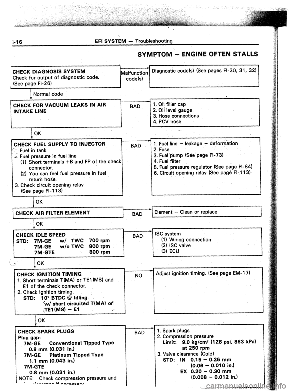
l-16 EFI SYSTEM - Troubleshooting
SYMPTOM - ENGINE OFTEN STALLS
CHECK DIAGNOSIS SYSTEM
Check for output of diagnostic code.
(See page Fl-26) * Diagnostic code(s) (See pages FI-30, 31, 32)
Malfunction
code(s)
Normal code
CHECK FOR VACUUM LEAKS IN AIR
INTAKE LINE BAD 1. Oil filler cap
2. Oil level gauge
3. Hose connections
4. PCV hose
I OK
CHECK FUEL SUPPLY TO INJECTOR
‘*-- Fuel in tank BAD
L. Fuel pressure in fuel line
(1) Short terminals +B and FP of the check
connector.
(2) You can feel fuel pressure in fuel
return hose. .
3. Check circuit opening relay
(See page FI-113) .
1. Fuel line - leakage - deformation
2. Fuse
3. Fuel.pump (See’ page FI-73)
4. Fuel filter
5. Fuel pressure regulator (See page FI-84)
6. Circuit opening relay (See page FI:1 13).
,
OK
CHECK AIR FILTER
I BAD Element - Clean or replace
OK
CHECK IDLE SPEED
STD: 7M-GE wl TWC 700 rpm
7M-GE w/o TWC 800 rpm
7M-GTE 800 rpm
t w
BAD ISC system
(I 1 Wiring connection
(21 ISC valve
(3) ECU
CHECK IGNITION TIMING ‘-
‘I. Short terminals TiMA) or TEl (MS) and
El of the check connector..
2. Check ignition timing.
STD: 10” BTDC @ Idling
short circuited T(MA) or
1
OK
CHECK SPARK PLUGS
Plug gap:
7M-GE Conventional Tipped Type
0.8 mm (0.031 in.)
7M-GE Platinum Tipped Type
1.1 mm (0.043 in.)
7M-GTE
0.8 mm (0.031 in.)
NOTE: Check compression pressure and
-I------- :+ -nyrpCCpn, c
NO
-I-
BAD - Adjust ignition timing. (See page EM-1 7)
1. Spark plugs
2. Compression pressure
Limit: 9.0 kg/cm2 (128 psi, 883
kPa)
at 250 rpm
3. Valve clearance (Cold)
STD: IN 0.15 - 0.25 mm
(0.06 - 0.010 in.)
Page 51 of 346
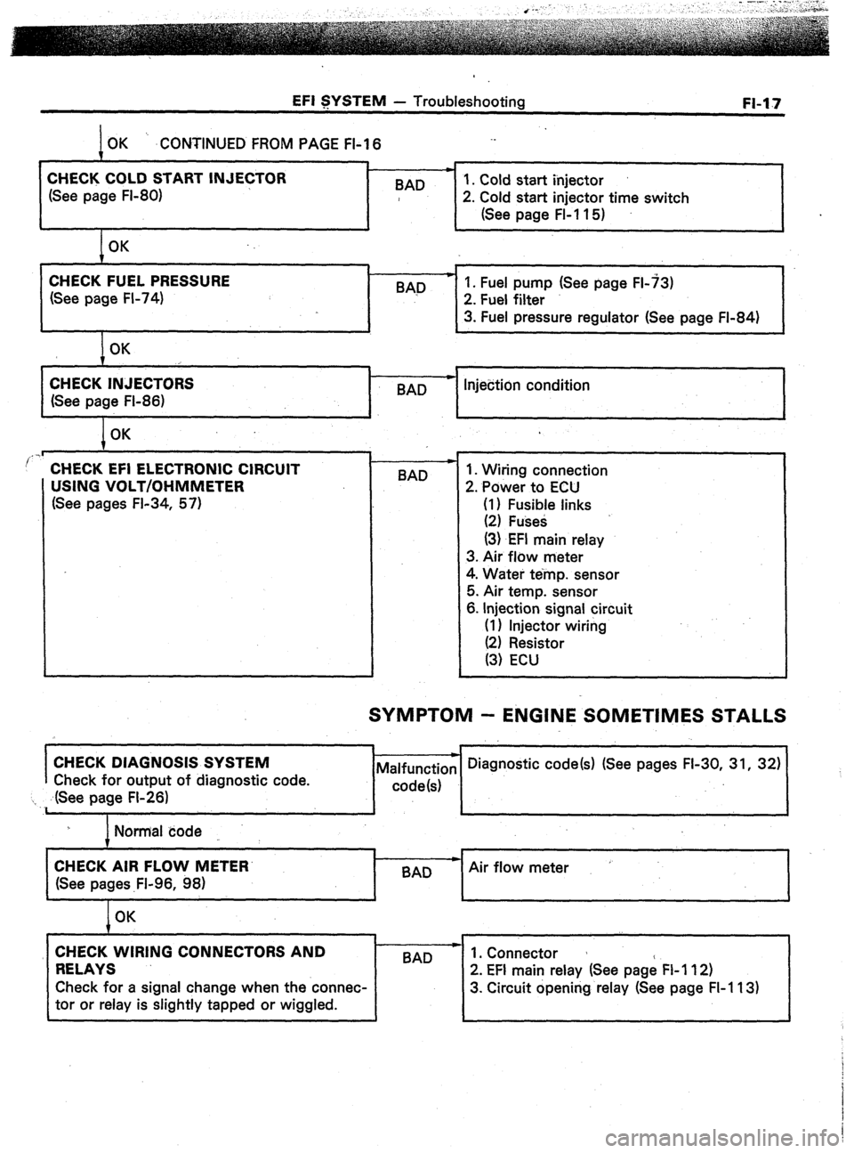
EFI SYSTEM - Troubleshooting
OK ‘. .CONTINUED FROM PAGE FI-I 6
m
CHECK COLD START INJECTOR
1. Cold start injector
(See page FI-80) BAD
2. Cold start injector time switch
(See page FL11 5)
OK FI-17
CHECK FUEL PRESSURE
(See page FI-74) BAD p 1. Fuel pump (See page FL73)
2. Fuel filter
3. Fuel pressure regulator (See page FI-84)
OK
CHECK INJECTORS
(See page FI-86) c
-
BAD Injection condition
I OK
..I
’ CHECK EFI ELECTRONIC CIRCUIT
USING VOLT/OHMMETER
(See pages FI-34, 57) BAD 1. Wiring connection
2. Power to ECU
(I) Fusible links
(2) Fuses
(3) EFI main relay
3. Air flow meter
4. Water temp. sensor
5. Air temp. sensor
6. Injection signal circuit
(I 1 Injector wiring
SYMPTOM - ENGINE SOMETIMES STALLS
I
CHECK DIAGNOSIS SYSTEM
Check for output of diagnostic code.
‘I ,. ,dSee page FI-26)
I Normal code
I
CHECK AIR FLOW METER’
Air flow meter
(See pages .Fl-96, 98)
I
OK
CHECK WIRING CONNECTORS AND
RELAYS 1 BAD --
2’ EFI main relay (See page FI 112)
Check for a signal change when the connec- 3. Circuit opening relay (See page FI-113)
tor or relay is slightly tapped or wiggled.
Page 54 of 346
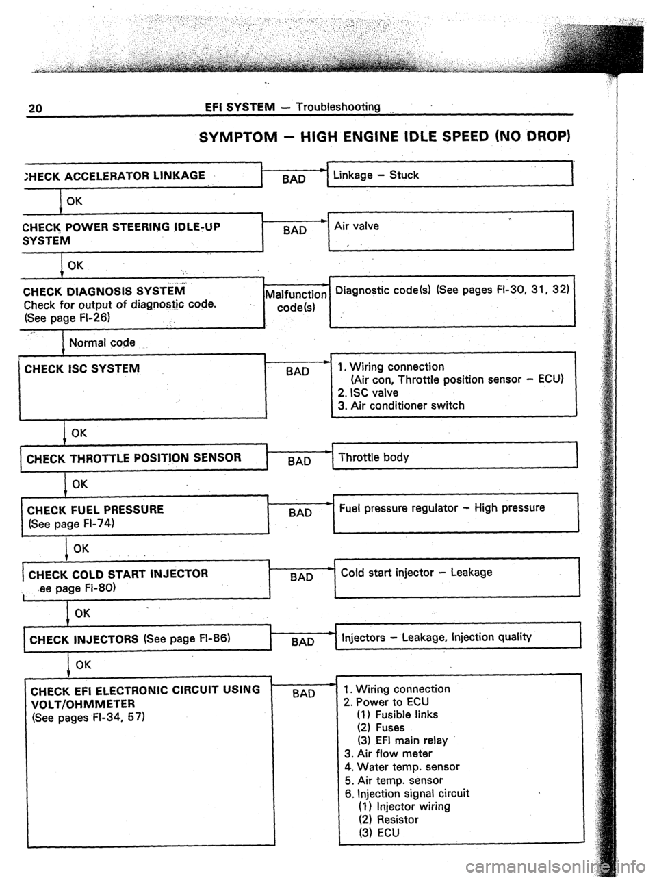
.20 EFI SYSTEM - Troubleshooting __
SYMPTOM - HIGH ENGINE IDLE SPEED (NO DROP)
:HECK ACCELERA
OK
CHECK POWER STEERING !DLE+JP
SYSTEM
OK .
‘:
j..l.
CHECK DIAGNOSIS SYSTEM
Check for output of diagnostic code.
(See page FI-26) ‘:.
_T I Linkage - Stuck
I
9
BAD * Air valve
I
r
* Diagnostic code(s) (See pages FI-30, 31, 32)
Malfunction
..
code!s)
Normal code
.
CHECK ISC SYSTEM
BAD
I
OK
71
(Air con Throttle posrtron sensor - ECU)
1 CHECK THROTTLE POSITION SENSOR
t-x- Throttle body
OK
CHECK FUEL PRESSURE
(See page FI-74) 7
BAD w Fuel pressure regulator - High pressure
OK
CHECK COLD START INJECTOR
~ .ee page FI-80) BAD w Cold start injector - Leakage
CHECK INJECTORS (See page FI-86)
I Injectors - Leakage, Injection quality
I OK
CHECK EFI ELECTRONIC CIRCUIT USING
VOLT/OHMMETER
(See pages FI-34, 57) BAD - 1. Wiring connection
2. Power to ECU
(1) Fusible links
(2) Fuses
(3) EFI main relay
3. Air flow meter
4. Water temp. sensor
5. Air temp. sensor
6. Injection signal circuit
(1) Injector wiring
(2) Resistor
(3) ECU