Page 358 of 962
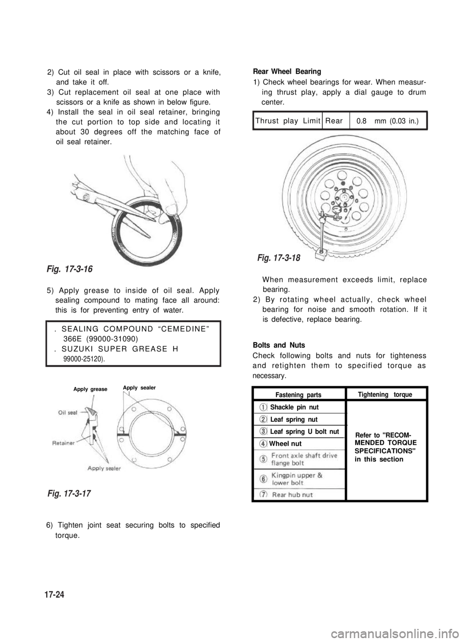
2) Cut oil seal in place with scissors or a knife,
and take it off.
3) Cut replacement oil seal at one place with
scissors or a knife as shown in below figure.
4) Install the seal in oil seal retainer, bringing
the cut portion to top side and locating it
about 30 degrees off the matching face of
oil seal retainer.
5) Apply grease to inside of oil seal. Apply
sealing compound to mating face all around:
this is for preventing entry of water.
. SEALING COMPOUND “CEMEDINE”
366E (99000-31090)
. SUZUKI SUPER GREASE H
99000-25120).
Apply greaseApply sealer,n
Rear Wheel Bearing
1) Check wheel bearings for wear. When measur-
ing thrust play, apply a dial gauge to drum
center.
Thrust play Limit Rear0.8 mm (0.03 in.)
1
When measurement exceeds limit, replace
bearing.
2) By rotating wheel actually, check wheel
bearing for noise and smooth rotation. If it
is defective, replace bearing.
Bolts and Nuts
Check following bolts and nuts for tighteness
and retighten them to specified torque as
necessary.
Fastening partsTightening torque
@ Shackle pin nut
@ Leaf spring nut
@ Leaf spring U bolt nut_Refer to "RECOM-
@ Wheel nut
6) Tighten joint seat securing bolts to specified
torque.
Fig. 17-3-16
Fig. 17-3-17
17-24
Fig. 17-3-18
MENDED TORQUE
SPECIFICATIONS"
in this section
Page 362 of 962
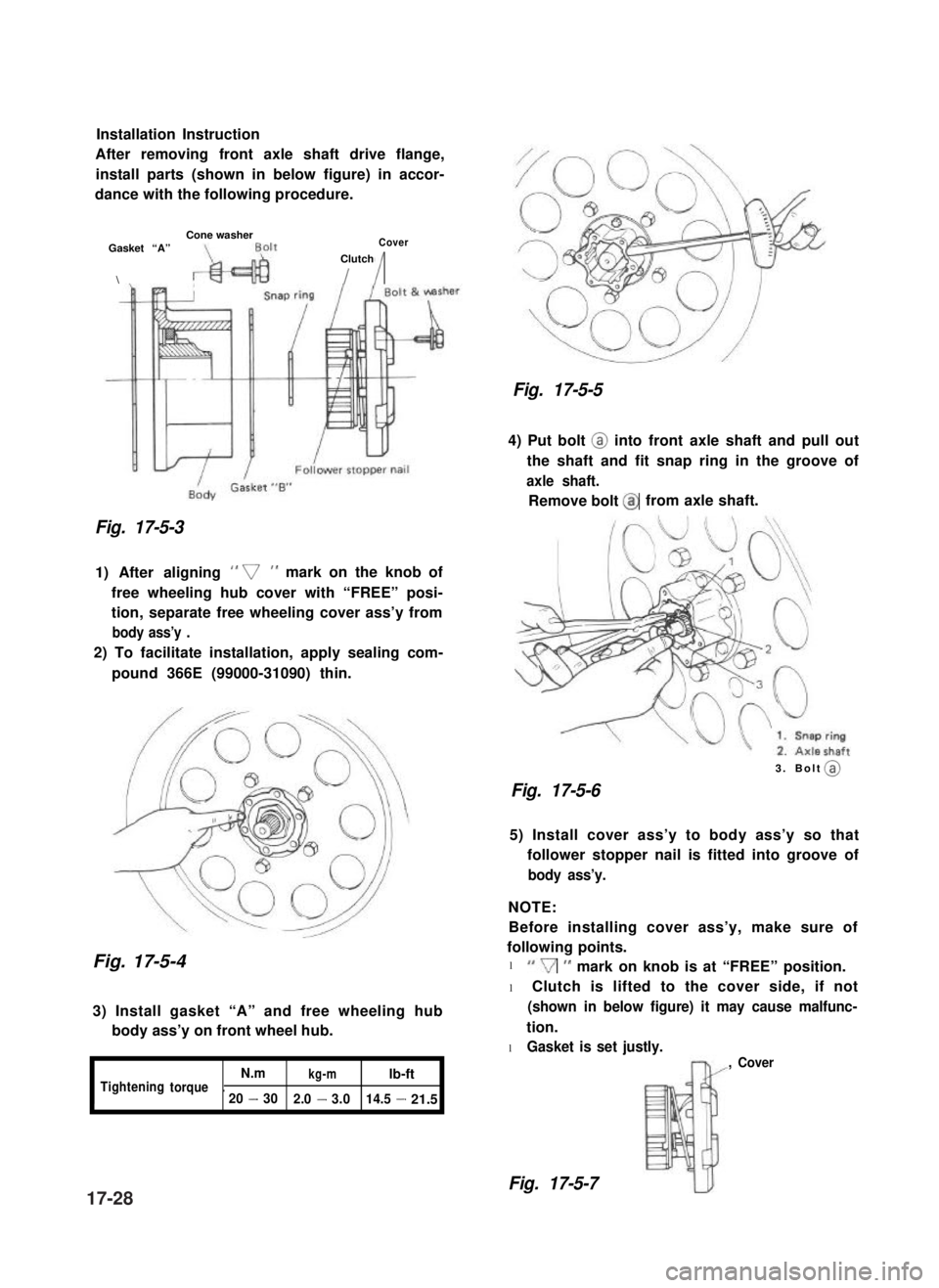
Installation Instruction
After removing front axle shaft drive flange,
install parts (shown in below figure) in accor-
dance with the following procedure.
Cone washerGasket “A”Cover
\
Clutch
II
Fig. 17-5-3
1) After aligning ” v” mark on the knob of
free wheeling hub cover with “FREE” posi-
tion, separate free wheeling cover ass’y from
body ass’y .
2) To facilitate installation, apply sealing com-
pound 366E (99000-31090) thin.
Fig. 17-5-4
3) Install gasket “A” and free wheeling hub
body ass’y on front wheel hub.
I
N.mkg-mlb-ftTighteningtorque.20-302.0-3.014.5-21.5
Fig. 17-5-5
4) Put bolt @ into front axle shaft and pull out
the shaft and fit snap ring in the groove of
axle shaft.
Remove bolt @from axle shaft.
3. Bolt (a)
Fig. 17-5-6
5) Install cover ass’y to body ass’y so that
follower stopper nail is fitted into groove of
body ass’y.
NOTE:
Before installing cover ass’y, make sure of
following points.
l “V” mark on knob is at “FREE” position.
l Clutch is lifted to the cover side, if not
(shown in below figure) it may cause malfunc-
tion.
l Gasket is set justly.
, Cover
Fig. 17-5-717-28
@
Page 363 of 962
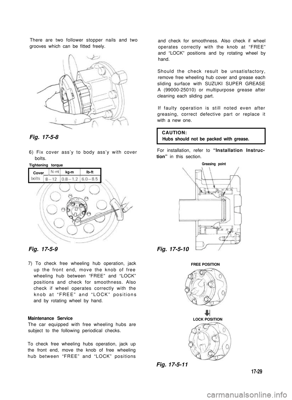
There are two follower stopper nails and two
grooves which can be fitted freely.
Fig. 17-5-8
6) Fix cover ass’y to body ass’y with cover
bolts.
Tightening torque
[ Cover [ N.m 1kg-mlb-ft
Fig. 17-5-9
7) To check free wheeling hub operation, jack
up the front end, move the knob of free
wheeling hub between “FREE” and “LOCK”
positions and check for smoothness. Also
check if wheel operates correctly with the
knob at “FREE” and “LOCK” positions
and by rotating wheel by hand.
Maintenance Service
The car equipped with free wheeling hubs are
subject to the following periodical checks.
To check free wheeling hubs operation, jack up
the front end, move the knob of free wheeling
hub between “FREE” and “LOCK” positions
and check for smoothness. Also check if wheel
operates correctly with the knob at “FREE”
and “LOCK” positions and by rotating wheel by
hand.
Should the check result be unsatisfactory,
remove free wheeling hub cover and grease each
sliding surface with SUZUKI SUPER GREASE
A (99000-25010) or multipurpose grease after
cleaning each sliding part.
If faulty operation is still noted even after
greasing, correct defective part or replace it
with a new one.
CAUTION:
Hubs should not be packed with grease.
For installation, refer to “Installation Instruc-
tion” in this section.
Greasing point
17-5-
FREE POSITION
+LOCK POSITION
Fig. 17-5-11
17-29
Fig. 17-5-10
Page 372 of 962
18-5. INSPECTION OF COMPONENTS
Steering Gear Box
[Oil level]
Oil surface should be up to the level as shown
in below figures. If not, add prescribed gear oil,
SAE 90.
Right hand steering vehicle
Fig. 18-17
Left hand steering vehicle
I
35mm(1.4 in.)
Fig. 18-18
[Adjustment of worm shaft starting torque]
The steering gear box is provided with adjust-
ing bolt @ which gives preload to sector shaft.
Fig. 18-19 (1)Adjusting bolt
Make an adjustment according to the following
procedure.
1) Check worm shaft to ensure that it is free
from thrust play.
2) Position pitman arm in parallel with worm
shaft as shown below.
(With pitman arm in this position, front
wheel is in straightforward state.)
Worm shaft
Fig. 18-20
Pitman arm
18-9
Page 377 of 962
Steering Column
Steering wheel slip ring
Apply SUZUKI SUPER GREASE A
(99000-25010) all around slip ring
IIbefore fining it. , 1
Steering column seal
\I
Steering column bolt
tightening torqueI
When installing the steering column,
1.
make sure to fit seal rubber in the
rubber
1J
Steering column nut
tightening torque
11 - 17N.m
1.1 - 1.7 kg-m
(8.0 - 12.0 lb-ft)
Fig. 18-30
position as illustrated
18-14
Page 381 of 962
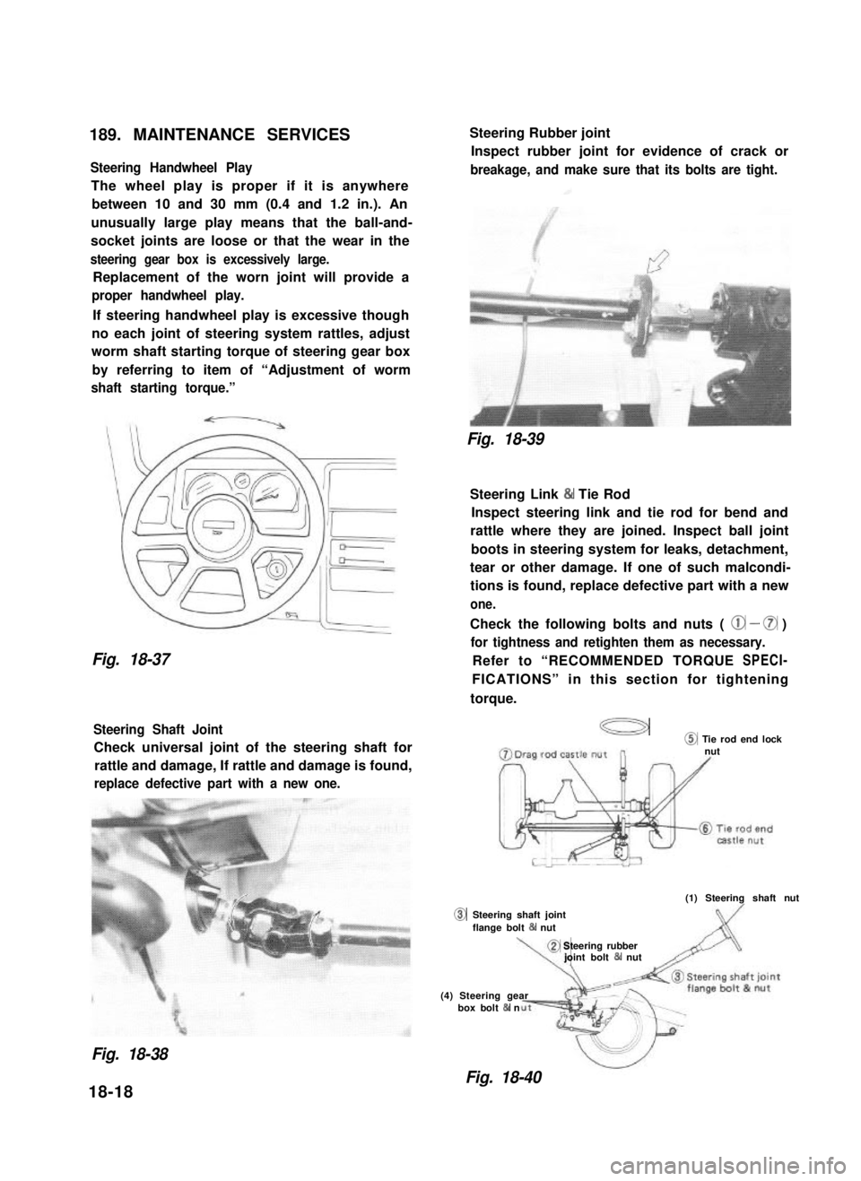
189. MAINTENANCE SERVICES
Steering Handwheel Play
The wheel play is proper if it is anywhere
between 10 and 30 mm (0.4 and 1.2 in.). An
unusually large play means that the ball-and-
socket joints are loose or that the wear in the
steering gear box is excessively large.
Replacement of the worn joint will provide a
proper handwheel play.
If steering handwheel play is excessive though
no each joint of steering system rattles, adjust
worm shaft starting torque of steering gear box
by referring to item of “Adjustment of worm
shaft starting torque.”
Fig. 18-37
Steering Shaft Joint
Check universal joint of the steering shaft for
rattle and damage, If rattle and damage is found,
replace defective part with a new one.
0
Steering Rubber joint
Inspect rubber joint for evidence of crack or
breakage, and make sure that its bolts are tight.
Fig. 18-39
Steering Link & Tie Rod
Inspect steering link and tie rod for bend and
rattle where they are joined. Inspect ball joint
boots in steering system for leaks, detachment,
tear or other damage. If one of such malcondi-
tions is found, replace defective part with a new
one.
Check the following bolts and nuts ( @ - 0 )
for tightness and retighten them as necessary.
Refer to “RECOMMENDED TORQUE SPECI-
FICATIONS” in this section for tightening
torque.
a@ Tie rod end locknut
(1) Steering shaft nut
Steering shaft jointflange bolt 84 nut
\,
@ Steering rubberjoint bolt & nut
(4) Steering gearbox bolt & n
Fig. 18-38
Fig. 18-40
18-18
Page 389 of 962
![SUZUKI GRAND VITARA 1987 Service Repair Manual MASTER CYLINDER ASSEMBLY
[GENERAL DESCRIPTION]
The master cylinder has two pistons and three piston cups. Its hydraulic pressure is produced in the
primary (“a” in the below figure) and secondary SUZUKI GRAND VITARA 1987 Service Repair Manual MASTER CYLINDER ASSEMBLY
[GENERAL DESCRIPTION]
The master cylinder has two pistons and three piston cups. Its hydraulic pressure is produced in the
primary (“a” in the below figure) and secondary](/manual-img/20/57437/w960_57437-388.png)
MASTER CYLINDER ASSEMBLY
[GENERAL DESCRIPTION]
The master cylinder has two pistons and three piston cups. Its hydraulic pressure is produced in the
primary (“a” in the below figure) and secondary (“b”) chambers. The hydraulic pressure produced in the
primary chamber (“a”) acts on the front wheel brakes (right & left).
Also, the hydraulic pressure produced in the secondary chamber (“b”) acts on the rear wheel brakes
(right & left).
NOTE:
Replace all components included in repair kits to service this master cylinder. Lubricate rubber parts with
clean, fresh brake fluid to ease assembly. Do not use lubricated shop air on brake parts as damage to rubber
components may result. If any hydraulic component is removed or brake line disconnected, bleed the
brake system. The torque values specified are for dry, unlubricated fasteners.
1.Piston stopper circllp
2.Piston stopper
3.Piston stopper sealing
4.Primary piston
5.Piston cup
6.Secondary piston pressure cup
7.Piston cup
8Secondary piston
9.Return spring secondary seat
10.Secondary piston return spring
11.Secondary piston stopper bolt
12.Master cylinder body
A :Primary piston
BSecondary piston
Fig. 19-3
[Master cylinder OPERATION]
Normal operation
Depressing the brake pedal forces the primary piston“A” to move to the left in the below figure and
consequently the hydraulic pressure is produced in the chamber “a”.
By means of this pressure and the return spring force, the secondary piston “B” is also pushed to the left
and thus the hydraulic pressure is produced in the chamber “b”.
Fig. 19-3-1
19-4
Page 404 of 962
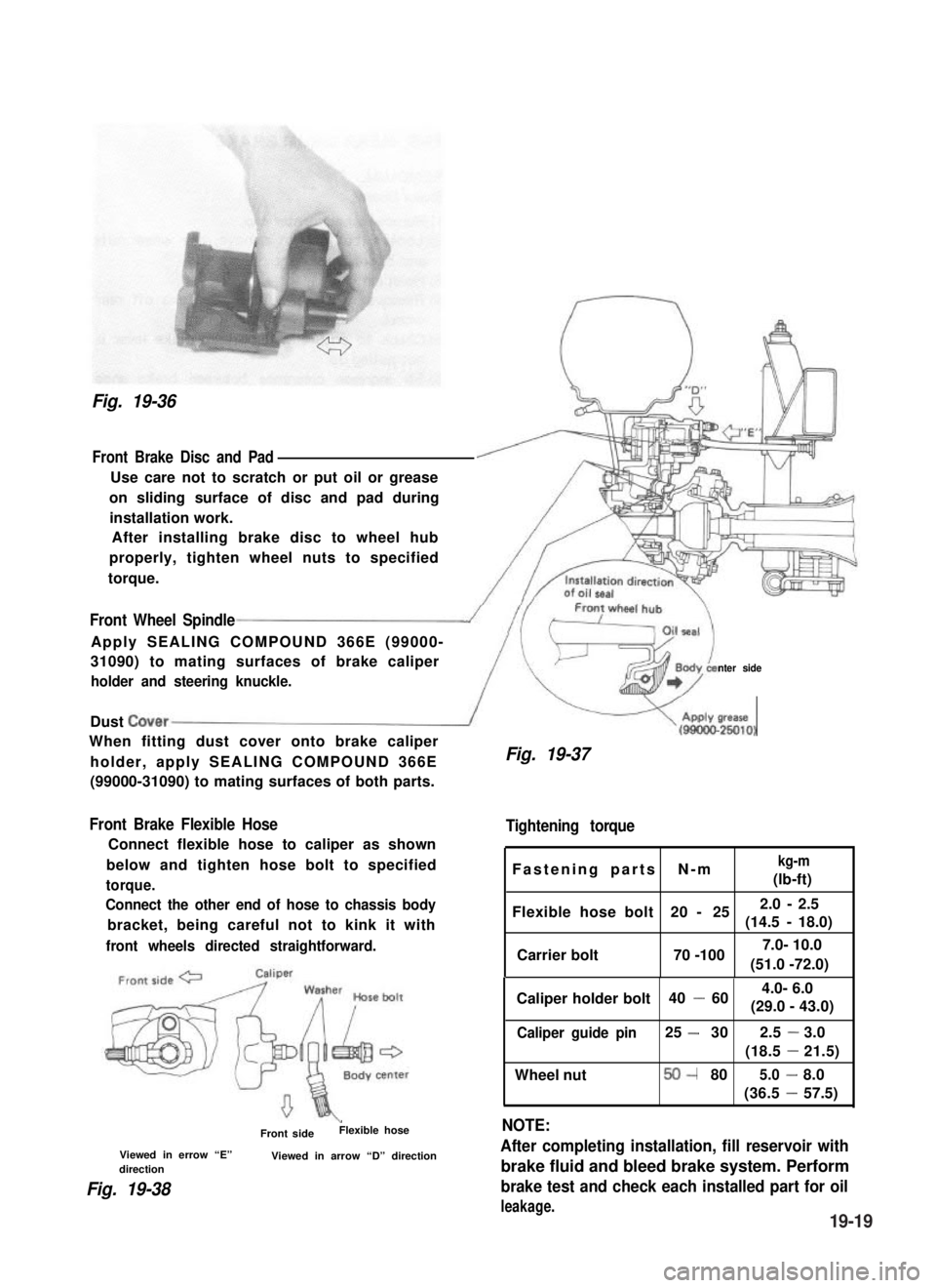
Fig. 19-36
Front Brake Disc and Pad
Use care not to scratch or put oil or grease
on sliding surface of disc and pad during
installation work.
After installing brake disc to wheel hub
properly, tighten wheel nuts to specified
torque.
Front Wheel Spindle
Apply SEALING COMPOUND 366E (99000-
31090) to mating surfaces of brake caliper
holder and steering knuckle.nter side
Dust Cover/
When fitting dust cover onto brake caliper
holder, apply SEALING COMPOUND 366E
(99000-31090) to mating surfaces of both parts.
Front Brake Flexible Hose
Connect flexible hose to caliper as shown
below and tighten hose bolt to specified
torque.
Connect the other end of hose to chassis body
bracket, being careful not to kink it with
front wheels directed straightforward.
\Front sideFlexible hose
Viewed in errow “E”Viewed in arrow “D” directiondirection
Fig. 19-38
V(gg!&
Fig. 19-37
Tightening torque
Fastening parts N-mkg-m
(lb-ft)
Flexible hose bolt 20 - 252.0 - 2.5
(14.5 -18.0)
Carrier bolt 70 -100
Caliper holder bolt 40 -60
Caliper guide pin25 -302.5-3.0
(18.5-21.5)
Wheel nut50-805.0-8.0
(36.5-57.5)
NOTE:
After completing installation, fill reservoir with
brake fluid and bleed brake system. Perform
brake test and check each installed part for oil
leakage.
(51.0 -72.0)
7.0- 10.0
4.0- 6.0
(29.0 - 43.0)
19-19