1987 SUZUKI GRAND VITARA wheel bolt torque
[x] Cancel search: wheel bolt torquePage 102 of 962
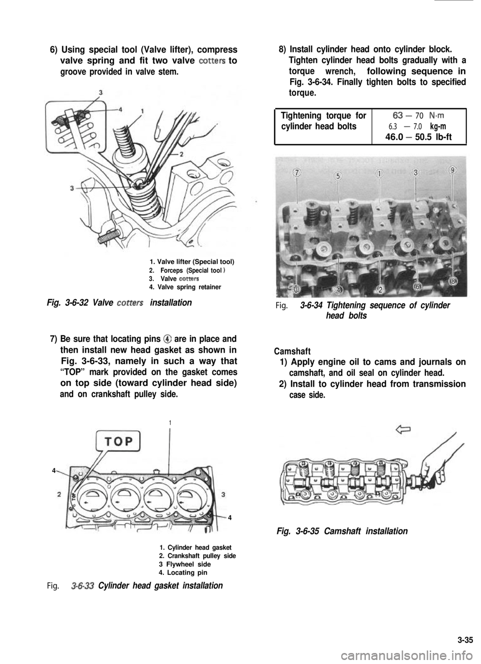
6) Using special tool (Valve lifter), compress
valve spring and fit two valve totters to
groove provided in valve stem.
1. Valve lifter (Special tool)
2.Forceps (Specialtool13.Valve totters4. Valve spring retainer
Fig. 3-6-32 Valve totters installation
7) Be sure that locating pins @ are in place and
then install new head gasket as shown in
Fig. 3-6-33, namely in such a way that
“TOP” mark provided on the gasket comes
on top side (toward cylinder head side)
and on crankshaft pulley side.
1
4
4
1. Cylinder head gasket2. Crankshaft pulley side
3 Flywheel side4. Locating pin
Fig. 3-6-33 Cylinder head gasket installation
8) Install cylinder head onto cylinder block.
Tighten cylinder head bolts gradually with a
torquewrench,following sequence in
Fig. 3-6-34. Finally tighten bolts to specified
torque.
Tightening torque for63-70 N-m
cylinder head bolts6.3-7.0 kg-m
46.0 -50.5 lb-ft
Fig. 3-6-34 Tightening sequence of cylinder
head bolts
Camshaft
1) Apply engine oil to cams and journals on
camshaft, and oil seal on cylinder head.
2) Install to cylinder head from transmission
case side.
Fig. 3-6-35 Camshaft installation
3-35
Page 105 of 962
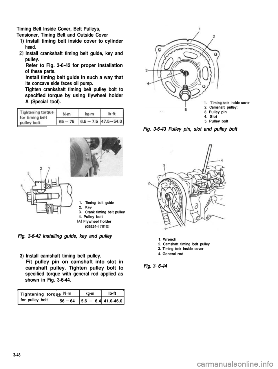
Timing Belt Inside Cover, Belt Pulleys,
Tensioner, Timing Belt and Outside Cover
1) install timing belt inside cover to cylinder
head.
2) Install crankshaft timing belt guide, key and
pulley.
Refer to Fig. 3-6-42 for proper installation
of these parts.
Install timing belt guide in such a way that
its concave side faces oil pump.
Tighten crankshaft timing belt pulley bolt to
specified torque by using flywheel holder
A (Special tool).
1.
2.3.
Timing belt guide
KeyCrank timing belt pulley4. Pulley bolt
(A) Flywheel holder
(09924-I 7810)
Fig. 3-6-42 Installing guide, key and pulley
3) Install camshaft timing belt pulley.
Fit pulley pin on camshaft into slot in
camshaft pulley. Tighten pulley bolt to
specified torque with general rod applied as
shown in Fig. 3-6-44.
inside cover2. Camshaft pulley:
3. Pulley pin4. Slot5. Pulley bolt
Fig. 3-6-43 Pulley pin, slot and pulley bolt
1. Wrench
2. Camshaft timing belt pulley3. Timing belt inside cover
4. General rod
Fig. 3- 6-44
Tightening torque N-mkg-mlb-ft
for pulley bolt56 - 645.6 - 6.4 41.0-46.0
3-48
Page 107 of 962
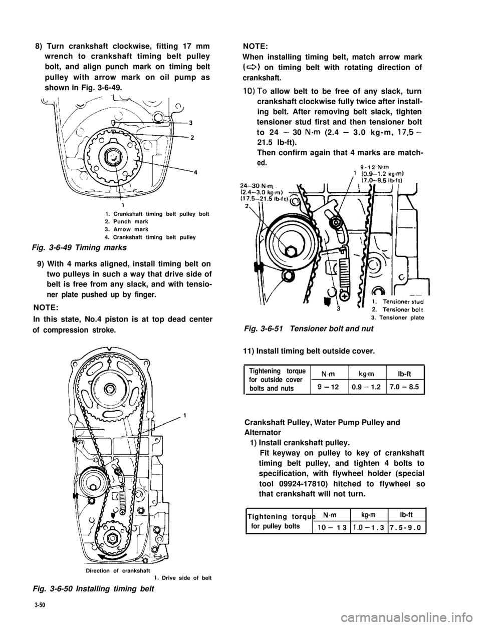
8) Turn crankshaft clockwise, fitting 17 mm
wrench to crankshaft timing belt pulley
bolt, and align punch mark on timing belt
pulley with arrow mark on oil pump as
shown in Fig. 3-6-49.
1. Crankshaft timing belt pulley bolt2. Punch mark3. Arrow mark
4. Crankshaft timing belt pulley
Fig. 3-6-49 Timing marks
9) With 4 marks aligned, install timing belt on
two pulleys in such a way that drive side of
belt is free from any slack, and with tensio-
ner plate pushed up by finger.
NOTE:
In this state, No.4 piston is at top dead center
of compression stroke.
NOTE:
When installing timing belt, match arrow mark
(+I on timing belt with rotating direction of
crankshaft.
10)To allow belt to be free of any slack, turn
crankshaft clockwise fully twice after install-
ing belt. After removing belt slack, tighten
tensioner stud first and then tensioner bolt
to 24 - 30 N.m (2.4 - 3.0 kg-m, 17,5 -
21.5 lb-ft).
Then confirm again that 4 marks are match-
ed.9-12 N-m
3. Tensioner plate
Fig. 3-6-51Tensioner bolt and nut
11) Install timing belt outside cover.
Tightening torque
for outside coverN.mkmlb-ft
bolts and nuts9- 120.9 - 1.27.0 - 8.5
Crankshaft Pulley, Water Pump Pulley and
Alternator
1) Install crankshaft pulley.
Fit keyway on pulley to key of crankshaft
timing belt pulley, and tighten 4 bolts to
specification, with flywheel holder (special
tool 09924-17810) hitched to flywheel so
that crankshaft will not turn.
Tightening torque N.mkg-mlb-ft
for pulley boltslo- 13 1.3 7.5-9.0*
Direction of crankshaft1. Drive side of belt
Fig. 3-6-50 Installing timing belt
3-50
Page 111 of 962
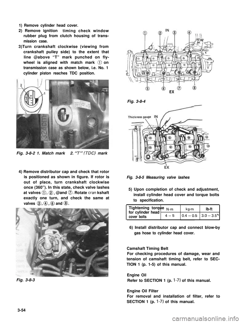
1) Remove cylinder head cover.
2) Remove ignitiontiming check window
rubber plug from clutch housing of trans-
mission case.
3)Turn crankshaft clockwise (viewing from
crankshaft pulley side) to the extent that
line @above “T” mark punched on fly-
wheel is aligned with match mark @ on
transmission case as shown below, i.e. No. 1
cylinder piston reaches TDC position.
Fig. 3-8-2 1. Match mark2. ‘7” (TDC) mark
4) Remove distributor cap and check that rotor
is positioned as shown in figure. If rotor is
out of place, turn crankshaft clockwise
once (360”). In this state, check valve lashes
at valves @,@I, @and 0. Rotate cran kshaft
exactly one turn, and check the same at
valves 8, @, @ and @I.
Fig. 3-8-3
EX
Fig. 3-8-4-
Fig. 3-8-5 Measuring valve lashes
5) Upon completion of check and adjustment,
install cylinder head cover and torque bolts
to specification.
Tightening torque N.,.,.,
for cylinder head Ib-mlb-ft
cover bolts4-50.4 - 0.53.0 - 3.5*
6) Install distributor cap and connect blow-by
gas hose to cylinder head cover.
Camshaft Timing Belt
For checking procedures of damage, wear and
tension of camshaft timing belt, refer to SEC-
TION 1 (p. 1-5) of this manual.
Engine Oil
Refer to SECTION 1 (p. I-7) of this manual.
Engine Oil Filter
For removal and installation of filter, refer to
SECTION 1 (p. I-7) of this manual.
3-54
Page 115 of 962
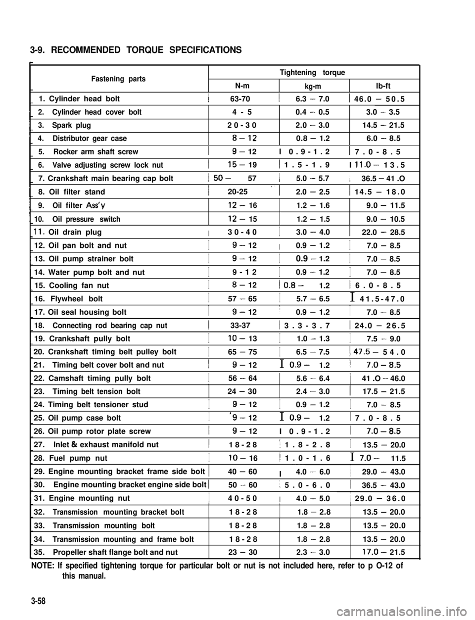
3-9. RECOMMENDED TORQUE SPECIFICATIONS
Fastening partsN-m
Tightening torque
kg-mlb-ft
1. Cylinder head bolt1 63-7016.3 - 7.01 46.0 - 50.5
2.Cylinder head cover bolt4-50.4-0.53.0-3.5
3.Spark plug20-302.0-3.014.5-21.5
4.Distributor gear case8-120.8-1.26.0-8.5
5.Rocker arm shaft screwI9- 12I 0.9-1.21 7.0-8.5
6.Valve adjusting screw lock nut
7. Crankshaft main bearing cap bolt
8. Oil filter stand
I15- 191 1.5-1.9I ll.O- 13.5
1 50- 5715.0 - 5.7136.5 - 41 .O
I20-25 -. 12.0 - 2.51 14.5 - 18.0
9.Oilfilter Ass’y12-161.2-1.69.0-11.5
10.Oilpressure switch12-151.2-1.59.0-10.5
11. Oil drain plugI30-40I3.0 - 4.0122.0 - 28.5
12. Oil pan bolt and nutI9- 12I0.9 - 1.2I7.0 - 8.5
13. Oil pump strainer bolt
14. Water pump bolt and nut
I9- 12I0.9 - 1.2I7.0 - 8.5
I9-12I0.9 - 1.2I7.0 - 8.5
15. Cooling fan nutI8- 121 0.8- 1.21 6.0-8.5
16. Flywheel boltI57 - 65I5.7 - 6.5I 41.5-47.0
17. Oil seal housing boltI9- 12I0.9 - 1.2I7.0 - 8.5
18.Connecting rod bearing cap nut1 33-37( 3.3-3.71 24.0 - 26.5
19. Crankshaft pully boltIlo- 13I1.0 - 1.3I7.5 - 9.0
20. Crankshaft timing belt pulley bolt
21.Timing belt cover bolt and nut
I65 - 75I6.5 - 7.51 47.5- 54.0
I9- 12I 0.9- 1.21 7-O-8.5
22. Camshaft timing pully boltI56 - 6415.6 - 6.4141 .O - 46.0III
23.Timingbelttensionbolt24-302.4-3.0117.5-21.5
24. Timing belt tensioner studI9- 12I0.9 - 1.2I7.0 - 8.5
25. Oil pump case boltI‘9- 12I 0.9- 1.21 7.0-8.5
26. Oil pump rotor plate screwI9- 12I 0.9-1.21 7-O-8.5
27.Inlet & exhaust manifold nutI18-281 1.8-2.8I13.5 - 20.0
28. Fuel pump nutIlo- 161 1.0-1.6I 7.0- 11.5
29. Engine mounting bracket frame side bolt 140 - 60I ~~~4.0 - 6.0129.0 - 43.0
30.Engine mounting bracket engine side bolt I50 - 601 5.0-6.0136.5 - 43.0
31. Engine mounting nutI40-50I4.0 - 5.01 29.0 - 36.0I1I
32.Transmissionmountingbracketbolt18-281.8-2.8113.5-20.0
33.Transmission mounting bolt18-281.8-2.813.5 -20.0
34.Transmission mounting and framebolt18-281.8-2.813.5 -20.0
35.Propeller shaft flange bolt and nut23 - 302.3-3.017.0-21.5
NOTE: If specified tightening torque for particular bolt or nut is not included here, refer to p O-12 of
this manual.
3-58
Page 255 of 962
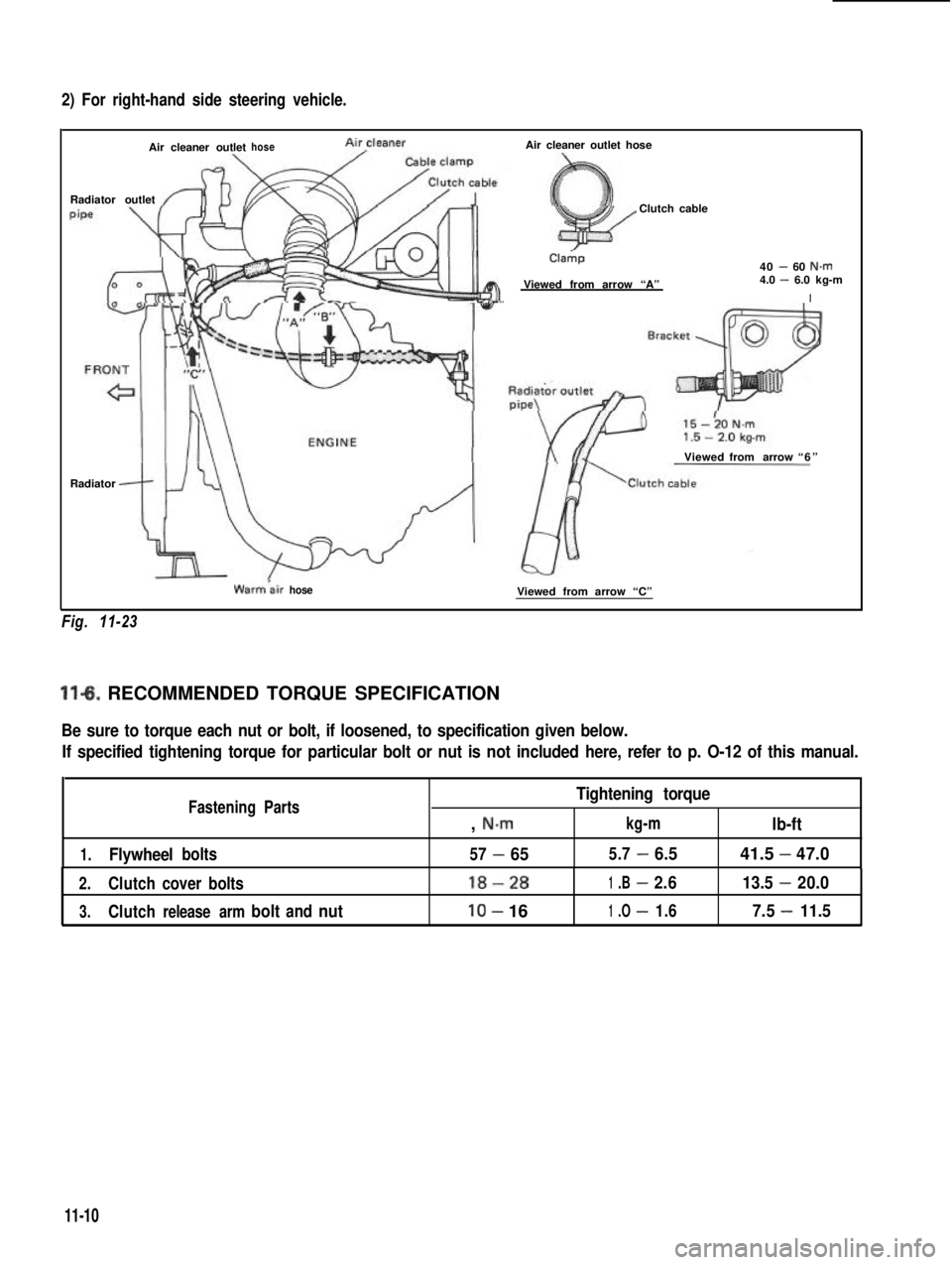
2) For right-hand side steering vehicle.
Air cleaner outlethoseAircleaner
Radiator outlet
Air cleaner outlet hose
Clutch cable
Cla&p
Viewed from arrow “A”
40 - 60 N.m4.0 - 6.0 kg-m
I
Viewedfrom arrow“6”
Radiator
Fig. 11-23
Warmair hoseViewed from arrow “C”
11-6. RECOMMENDED TORQUE SPECIFICATION
Be sure to torque each nut or bolt, if loosened, to specification given below.
If specified tightening torque for particular bolt or nut is not included here, refer to p. O-12 of this manual.
Fastening PartsTightening torque
, N.mkg-mlb-ft
1.Flywheelbolts57-655.7-6.541.5-47.0
2.Clutchcover bolts18-281.B-2.613.5-20.0
3.Clutchrelease armboltandnutlo- 161.O-1.67.5-11.5.
11-10
Page 333 of 962
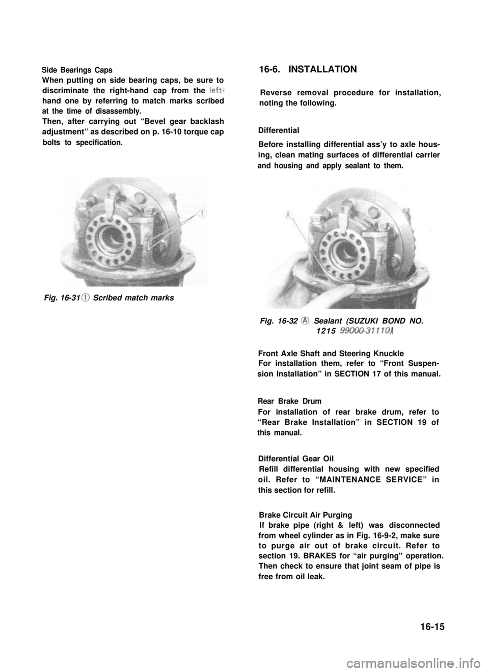
Side Bearings Caps
When putting on side bearing caps, be sure to
discriminate the right-hand cap from the left-
hand one by referring to match marks scribed
at the time of disassembly.
Then, after carrying out “Bevel gear backlash
adjustment” as described on p. 16-10 torque cap
bolts to specification.
16-6. INSTALLATION
Reverse removal procedure for installation,
noting the following.
Differential
Before installing differential ass’y to axle hous-
ing, clean mating surfaces of differential carrier
and housing and apply sealant to them.
Fig. 16-31 0 Scribed match marks
Fig. 16-32 @ Sealant (SUZUKI BOND NO.
1215 99000-31110)
Front Axle Shaft and Steering Knuckle
For installation them, refer to “Front Suspen-
sion Installation” in SECTION 17 of this manual.
Rear Brake Drum
For installation of rear brake drum, refer to
“Rear Brake Installation” in SECTION 19 of
this manual.
Differential Gear Oil
Refill differential housing with new specified
oil. Refer to “MAINTENANCE SERVICE” in
this section for refill.
Brake Circuit Air Purging
If brake pipe (right & left) was disconnected
from wheel cylinder as in Fig. 16-9-2, make sure
to purge air out of brake circuit. Refer to
section 19. BRAKES for “air purging" operation.
Then check to ensure that joint seam of pipe is
free from oil leak.
16-15
Page 357 of 962
Before giving a test pull to knuckle arm with a
spring balance in the alternative method, in-
stall a large amount of shims on each kingpin to
lighten preload on tapered roller bearing.
Keep on reading the torque, each time decreas-
ing shim thickness a little, and continue this
process until specified torque value is obtained.
(This process protects kingpins because it ensure
that no excessive pull will be applied to bearings
at the onset.) If the process fails to produce
specified torque, that is, if desired torque
resistance does not occur even when shim
thickness has been reduced to zero on each
kingpin, it means that bearings or kingpins are
excessively worn and need replacement.
NOTE:
l Read spring balance indication when knuckle
arm begins to turn. In other words, you are
to read “starting torque.”
l When checking knuckle arm starting torque,
be sure to have axle hub oil seal removed
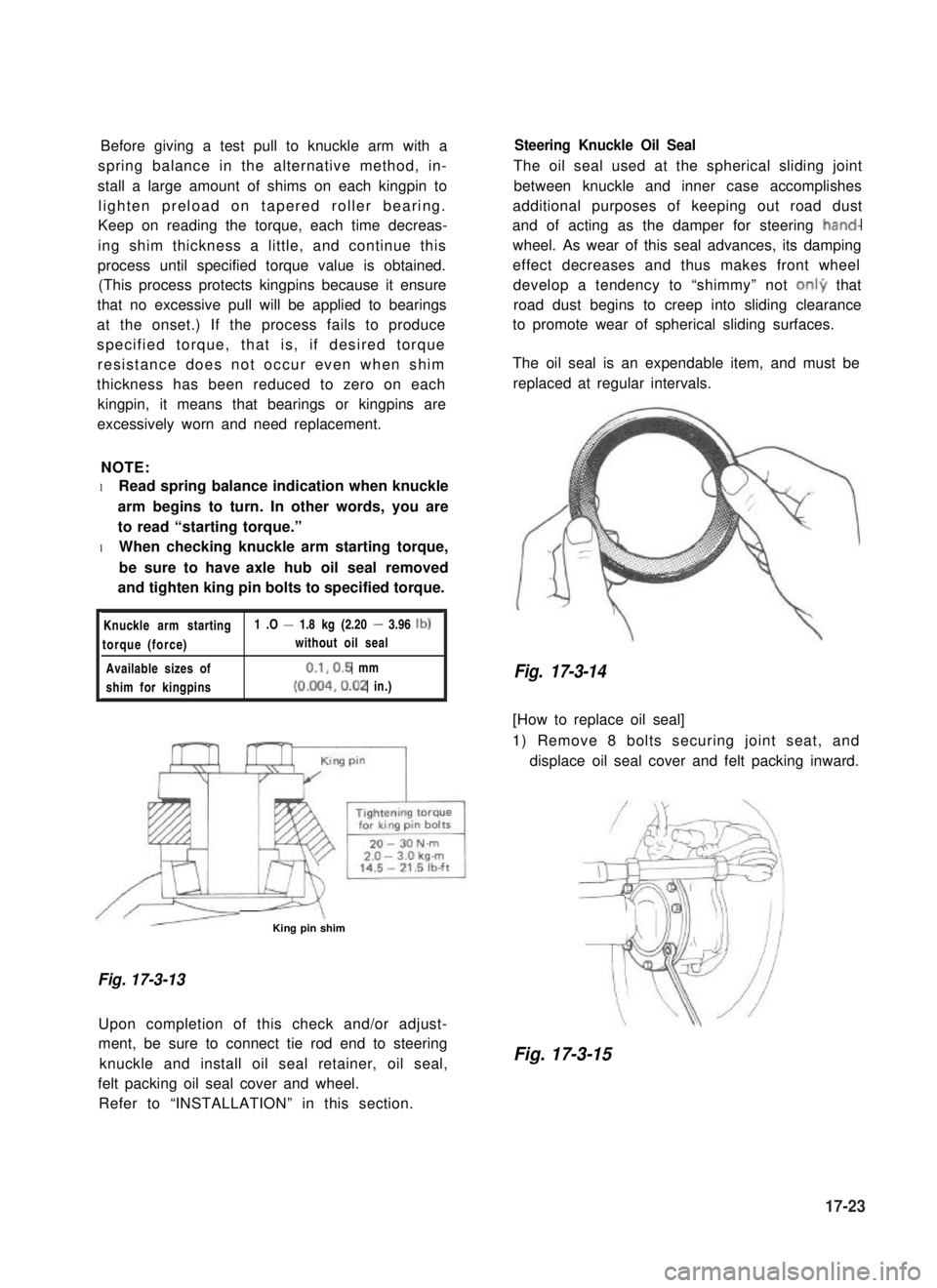
and tighten king pin bolts to specified torque.
Knuckle arm starting1 .O - 1.8 kg (2.20 - 3.96 lb)
torque (force)without oil seal
Available sizes of0.1,0.5 mm
shim for kingpins(0.004,0.02 in.)
/r--QzL- -\King pin shim
Fig. 17-3-13
Upon completion of this check and/or adjust-
ment, be sure to connect tie rod end to steering
knuckle and install oil seal retainer, oil seal,
felt packing oil seal cover and wheel.
Refer to “INSTALLATION” in this section.
Steering Knuckle Oil Seal
The oil seal used at the spherical sliding joint
between knuckle and inner case accomplishes
additional purposes of keeping out road dust
and of acting as the damper for steering hand-
wheel. As wear of this seal advances, its damping
effect decreases and thus makes front wheel
develop a tendency to “shimmy” not onI9 that
road dust begins to creep into sliding clearance
to promote wear of spherical sliding surfaces.
The oil seal is an expendable item, and must be
replaced at regular intervals.
Fig. 17-3-14
[How to replace oil seal]
1) Remove 8 bolts securing joint seat, and
displace oil seal cover and felt packing inward.
Fig. 17-3-15
17-23