1987 MITSUBISHI MONTERO radiator
[x] Cancel search: radiatorPage 3 of 284

INTRODUCTION - H
ow To Use This Manual 3
-L
!
Page number
Group title
Section title
THERMOSTAT
REMOVAL AND INSTALLATION
I
I I
L
1 torque
Removal +
I s 0480031
Thermostat kit
Repair kit or set parts are
1. Connectw of water temperature switch
connector (Vehicles with an air condltlon-
eri
2 Connection of radiator upper hose
3 Water outlet fitting
4 Water outlet fitting gasket
B~C 5. Thermostat I
This number corresponds to
the number in “Removal
steps”, ” Disassembly
steps”, “Installation steps”
or “Reassembly steps”.
NOTE
(1)
(3)
q Nowreusable parts
-r Reverse the removal procedures to reinstall
12) l * : Refer to “Sewce Points of Installation”
SERVICE POINTS OF lNSTALLATlON--
45. INSTALLATION OF THERMOSTAT
Install the thermostat to the Intake manifold as illustrated.
Caution
The thermostat flange fits over the manifold seat;
ensure that the thermostat is not installed at an angle.
An explanation of procedures, notes, etc.
(and reassembly. ’ ’ -1 regarding removal installation disassembly
Page 45 of 284

Position of guide to prevent
improper connection
fl!liB
9-wire connector
WIRING HARNESS - How to Read Wiring Diagrams 8-25
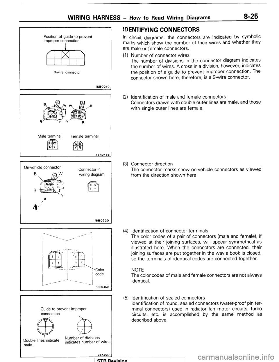
IDENTIFYING CONNECTORS
In circuit diagrams, the connectors are indicated by symbolic
marks which show the number of their wires and whether they
are male,or female connectors.
(1) Number of connector wires
The number of divisions in the connector diagram indicates
the number of wires. A cross in a division, however, indicates
the position of a guide to prevent improper connection. The
connector shown here, therefore, is a g-wire connector.
1680219
R
jpg$&’
-y v
R
Male terminal
Female terminal
On-vehicle connector
Connector in
wiring diagram
I 1680220
r
16R0459
Guide to prevent improper
connection
@ Numb&ions
Double lines indicate
male. Indicates number of wires
36KO37
(2) Identification of male and female connectors
Connectors drawn with double outer lines are male, and those
with single outer lines are female.
(3) Connector direction
The connector marks show on-vehicle connectors as viewed
from the direction shown here.
(4) Identification of connector terminals
The color codes of a pair of connectors (male and female), if
viewed at their joining surfaces, will appear symmetrical as
illustrated here. When the connectors are connected, their
joining surfaces are put together in the way a book is closed,
so the terminals of identical codes are connected together.
NOTE
The color codes of male and female connectors are not always
identical.
(5) Identification of sealed connectors
Identification of round, sealed connectors (water-proof pin ter-
minal connectors) used in radiator fan motor circuits, turbo
circuits, etc. is accomplished by the same method as
described above.
/ STB Revision
Page 178 of 284

8-158 LIGHTING SYSTEM - Headlight
Post-installation Operation l Adjustment of Headliaht Aimina (
HEADLIGHT
REMOVAL AND INSTALLATION NOBIJAE
( fer to P.8-157.) Removal steps
1. Radiator grille
2. Front combinatior
3. Headlight bezel
4. Retaining ring
5. Headlight
I light
NOTE
Reverse the removal procedure to reinstall.
16W963
iswasa
INSPECTION
HEADLIGHT CONTROL RELAY
Remove the headlight control relay from the inner side of the
left fender shield.
For models equipped with headlight washers, remove the
headlight washer tank, and then remove the headlight control
relay.
Check for continuity between the terminals while power is
being supplied and while it is not. Terminal 1 2 3 4 5 6
Battery voltage
not applied
Battery voltage
applied
NOTE
(I 1 C-C indicates that there is continuity between the terminals.
(2) O--O indicates the connection with the power supply.
ewision I
Page 199 of 284

I 1
+ -
li.if 1
2
WIPER AND WASHER SYSTEM - Rear Washer / Headlight Washer 8-179 (1) Check to be sure that there is washer fluid in the washer
tank.
(2) Check to be sure that the washer motor operates and the
fluid is forced out under pressure when the battery’s
positive (+) terminal is connected to terminal 2 and the
negative (-) terminal is connected to terminal 1.
INSPECTION
WASHER MOTOR AND PUMP Make the check while the motor is installed to the washer
tank.
SERVICE POINTS OF INSTALLATION
1. INSTALLATION OF REAR WHEELHOUSE TRIM AND
QUARTER TRIM Refer to GROUP 23 BODY - Trims.
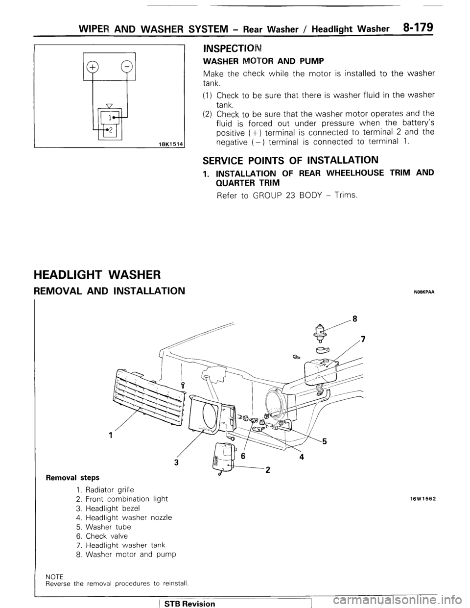
HEADLIGHT WASHER
REMOVAL AND INSTALLATION NOEKPAA
Removal steps 1. Radiator grille
2. Front combination light
3. Headlight bezel
4. Headlight washer nozzle
5. Washer tube
6. Check valve
7. Headlight washer tank
8. Washer motor and pump
16W1562
NOTE Reverse the removal procedures to reinstall.
) STB Revision
Page 206 of 284

8486 HORN - Horn
HORN
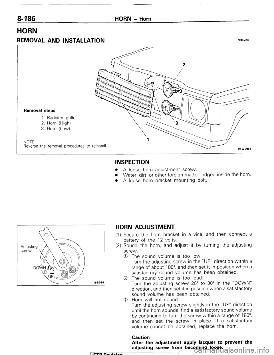
REMOVAL AND INSTALLATION NOBWAE
Removal steps
1. Radiator grille
2. Horn (High)
3. Horn (Low)
NOTE Reverse tne removal procedures to
reinstall.
16W964
169744
INSPECTION o A loose horn adjustment screw.
o Water, dirt, or other foreign matter lodged inside the horn.
l A loose horn bracket mounting bolt.
HORN ADJUSTMENT (1) Secure the horn bracket in a vice, and then connect a
battery of the 12 volts.
(2) Sound the horn, and adjust it by turning the adjusting
screw.
0 The sound volume is too low.
Turn the adjusting screw in the “UP” direction within a
range of about 180”, and then set it in position when a
satisfactory sound volume has been obtained.
0 The sound volume is too loud:
Turn the adjusting screw 20” to 30” in the “DOWN”
direction, and then set it in position when a satisfactory
sound volume has been obtained.
0 Horn will not sound:
Turn the adjusting screw slightly in the “UP” direction
until the horn sounds, find a satisfactory sound volume
by continuing to turn the screw within a range of 180”,
and then set the screw in place. If a satisfactory
volume cannot be obtained, replace the horn.
Caution
After the adjustment apply lacquer to prevent the
adjusting screw from becoming loose.
1 ST6 Revision
Page 244 of 284

24-8 HEATERS - Service Adjustment Procedures
ater valve cover
2OW751
WAiER VALVE REPLACEMENT N24FBAC
I. Set the temperature control lever to the extreme right
position.
2. Remove the radiator drain plug, and then drain the engine
coolant.
3. Remove the air filter
4. Remove the heater hose clamp to disconnect the heater
hose.
5. Disconnect the water valve control wire from the blend air
damper lever and the heater unit’s clip.
6. Remove the water valve cover.
7. Remove the piping clamp.
8. Unfasten the clip of blend air damper lever, and disconnect
the link for the water valve lever from the blend air damper
lever.
9. Remove the joint hose clamp.
10. Cut the joint hose.
11. Remove the water valve from the heater core.
12. Apply a coating of soapy water to the inside surface of the
new joint hoses, and then connect them to the pipe part of
the water valve and the heater core.
13. Connect the link, and then install the heater cover.
1 STB Revision
Page 248 of 284

24-12 HEATERS - Heater Unit
I
HEATER UNBT
REMOVAL AND INSTALLATION
Pre-removal Operation
0 Draining of Coolant
(Refer to GROUP 0 LUBRICATION
AND MAINTENANCE-Maintenance
Service)
Post-installation Operation
0 Supplying of Coolant
(Refer to GROUP 0 LUBRICATION
AND MAINTENANCE-Maintenance
Service) Removal steps
l *
I, Heater hose connection
+* l 4
2. Instrument panel
3. Duct
4. Center ventilator duct
5. Heater unit
NOTE
(1) Reverse the removal procedures to reinstall.
(2) +e : Refer to “Service Points of Removal”
(3) l
+ : Refer to “Service Points of Installation”
2OW823
SERVICE POINTS OF REMOVAL
1. DISCONNECTION OF HEATER HOSES (1) Remove the air filter.
(2) Set the temperature lever to the far
(3) Remove the radiator drain plug and
engine coolant.
(4) Remove the heater hose clamp, and
heater hose.
N24lBAE right position.
then drain the
disconnect the
ETB Revision
Page 256 of 284

24-20 AIR-CONDITION!NG-General Information
I
AIR-CONDITIONING SYSTEM COMPO
N24BBBB
Condenser MDuct, joint (Blower side)
oint (Heater unit
Condenser
2OWB31
Suction Pipe Receiver bracket side)
COMPRESSOR - The prime purpose of the compressor is to compress the low pressure refrigerant vapor
from the evaporator into a high pressure, high temperature vapor. The 6 cylinder 6P148 compressor is used.
MAGNETIC CLUTCH is mounted on the compressor providing a convenient way to drive and disengage
compressor in accordance to the cooling needs. CONDENSER is located in front of the radiator. Its function
is to cool the hot, high pressure refrigerant gas causing it to condense into high pressure liquid refrigerant.
RECEIVER DRIER is used to remove any traces of moisture from the refrigerant system. This component
incorporates the sight glass and fusible plug. SIGHT GLASS at the top of the receiver drier is provided as a
diagnostic tool to observe refrigerant flow and observe refrigerant level. THE FUSIBLE PLUG is located on
the receiver drier. Its function is to prevent damage to the air conditioning system in the event that
excessive pressure develops due to condenser air flow being restricted by, for example, leaves, newspaper,
an overcharge of refrigerant, or air in the system. LOW PRESSURE SWITCH prevents damage to the
compressor in case of system loss of refrigerant charge. EXPANSION VALVE - The expansion valve is used
for all applications. Its function is to meter refrigerant into the evaporator in accordance with cooling
requirements. EVAPORATOR COIL is located in the unit and its function is to cool and dehumidify the air
before it enters the vehicle. FREEZE UP CONTROL FIN THERMOSTAT SENSOR is installed at the heater
side of evaporator. The main function of a freeze control is to keep condensate water on the face of the
evaporator coil from freezing and restricting air flow. WATER TEMPERATURE SWITCH - When the
temperature of the radiator coolant became high, this switch functions to stop the compressor and prevent
engine overheating. SERVICE VALVE at the compressor and the discharge line. The valves are used to test
and service the refrigerant system. REFRIGERANT R-12 is used maximum amount 907 g (32 oz.) R-12.
COMPRESSOR OIL is used DENS0 oil 6 maximum amount 110 cc (3.7 U.S.fl.oz., 3.9 Imp.fl.oz.).
/ STB Revision