1987 MITSUBISHI MONTERO sensor
[x] Cancel search: sensorPage 1 of 284

Service Manual
MONTERO
1987 : Volume 2
FOREWORD
This Service Manual has been prepared with the
latest service information available at the time of
publication. It is subdivided into various group
categories and each section contains diagnosis,
disassembly, repair, and installation procedures
along with complete specifications and tightening
references. Use of this manual will aid in properly
performing any servicing necessary to maintain or
restore the high levels of performance and reliability
designed into these outstanding vehicles.
WE SUPPORT
VOLUNTARY TECHNICIAN
CERTIFICATION THROUGH
MITSUBISHI MOTOR SALES OF AMERICA. Inc.
Mitsubishi Motors corporation reserves the right to make changes in
design or to make additions to or improvements in its products without
imposing any obligations upon itself to install them on its products
previously manufactured.
I
GROUP/SECTION INDEX ‘kme-.
INTRODUCTION ..............................
Electrical ...........................................
Electrical System Parts
Location .........................................
Relays, Control Units, Sensors,
Fuses, Groundings
Inspection of Harness
Connector ......................................
Wiring Harness .............................
Charging System ..........................
Starting System ............................
Ignition System .............................
Meters and Gauges ......................
Lighting System .............................
Wiper and Washer System ..........
Horn ...............................................
Accessory ......................................
Audio System ................................
Back Door Window Defogger ......
Automatic Free-wheeling Hub
Indicator System ..........................
Heaters and Air-conditioning .........
Heaters ..........................................
Air-conditioning ............................
**, For Engine Chassis & Body refer to
0 1986 Mitsubishi Motors Corporation Printed in Japan
Page 11 of 284

INTRODUCTION - Precautions Before Service 11
I
OOY63:
oOY58S IOA 15A
1 Permissible current 1
Nominal
size
0.3 mm2 AWG22 5A
05mm’ AWG 20
AWG18 ~ zi 13A
0.85 mm2 17A
1.25 mm2 AWG 16 12A 22A
2.0 mm2 AWG14 I 16A 30A
ELECTRICAL COMPONENTS
1. When installing any of the vehicle parts, be careful not to
pinch or damage any of the wiring harnesses.
2. Sensors, relays, etc., are sensitive to strong impacts.
Handle them with care so that they are not dropped or
mishandled.
3. The electronic parts used for relays, etc., are sensitive to
heat, If any service which causes a temperature of 80°C
(176°F) or more is performed, remove the part or parts in
question before carrying out the service.
FUSES AND FUSIBLE LINKS
1. If a blown-out fuse is to be replaced, be sure to use only a
fuse of the specified capacity. If a fuse of a capacity larger
than that specified is used, parts may be damaged and the
circuit may not be protected adequately.
Caution
If a fuse is blown-out, be sure to eliminate the cause of
the problem before installing a new fuse.
2 If additional optional equipment is to be installed in the
vehicle, follow the procedure listed in the appropriate
instruction manual; however, be sure to pay careful
attention to the following points:
(1) In order to avoid overloading the wiring, take the
electrical current load of the optional equipment into
consideration, and determine the appropriate wire size.
(2) Where possible, route the wiring through the existing
harnesses.
I Revision
Page 21 of 284

8-1
ELECTRICAL
CONTENTS
NOBAA-
ACCESSORY ......................................................
188
Cigarette Lighter ............................................
,190
Clock ...............................................................
,191
AUDIO SYSTEM ................................................
.192
AUTOMATIC FREE-WHEELING HUB
INDICATOR SYSTEM ........................................
208
Automatic Free-wheeling Hub
Indicator Control Unit
..................................... ,216
Pulse Generator ..............................................
215
BACK DOOR WINDOW DEFOGGER
................ .203
Defogger switch ............................................
,206
Printed Heater Lines
...................................... ,207
CHARGING SYSTEM .........................................
71
Alternator ........................................................
83
Service Adjustment Procedures
..................... 77
Battery Charging ........................................
82
Inspection of Battery ..................................
81
Output Current Test ...................................
78
Regulated Voltage Test ..............................
79
Voltage Drop Test of Alternator Output
Wire ............................................................
77
ELECTRICAL SYSTEM PARTS LOCATION
...... 2
Diode ...............................................................
5
Fusible Link and Fuse
..................................... 6
Grounding .......................................................
7
Relay and Control Unit ....................................
2
Sensor .............................................................
4
HORN ..................................................................
184
Horn Switch
.................................................... 187
IGNITION SYSTEM ............................................
105
Ignition Switch
................................................ 122
Ignition System ...............................................
1 14
Service Adjustment Procedures
.................... .l 1 1
Checking Ignition System
..........................
11 1
Checking Ignition Timing
...........................
11 1
Spark Plug Cable Test
................................
1 12
Spark Plug Test
.......................................... 1 12 INSPECTION OF HARNESS CONNECTOR ...... 9
Check for Improper Engagement of
Terminal .......................................................... 9
Continuity and Voltage Test for Connector .... 9
Engaging and Disengaging of Connector
Terminal ..........................................................
9
LIGHTING SYSTEM ........................................... 143
Column Switch
................................ .
.............. .I59
Dimmer Control Switch
................................. .I62
Hazard Warning Switch
................................. .I61
Headlight ........................................................ ,158
Service Adjustment Procedures
.................... .I57
Headlight Aiming .......................................
157
METERS AND GAUGES .................................... 123
Service Adjustment Procedures
.................... .I30
Fuel Gauge Simple Test ................................. .I31
Fuel Gauge Unit Inspection ........................... .I31
Oil Pressure Gauge Simple Test
.................... .I32
Oil Pressure Gauge Unit Simple Test
............ ,132
Speedometer Inspection
............................... .I30
Tachometer Inspection .................................. ,130
Voltage Meter Simple Test
............................ .I33
Water Temperature Gauge Simple Test
....... ..I3 1
Water Temperature Gauge Unit Inspection
. ..I3 2
STARTING SYSTEM .......................................... 91
Starter Motor ............ ....................................... 97
WIPER AND WASHER SYSTEM
....................... .163
WIRING HARNESS ............................................ 13
Centralized Junction ....................................... 69
Circuit Diagram ............................................... 34
Configuration Diagram .................................... 27
How to Read Wiring Diagrams ....................... 20
Troubleshooting .............................................. 13
Page 24 of 284

8-4
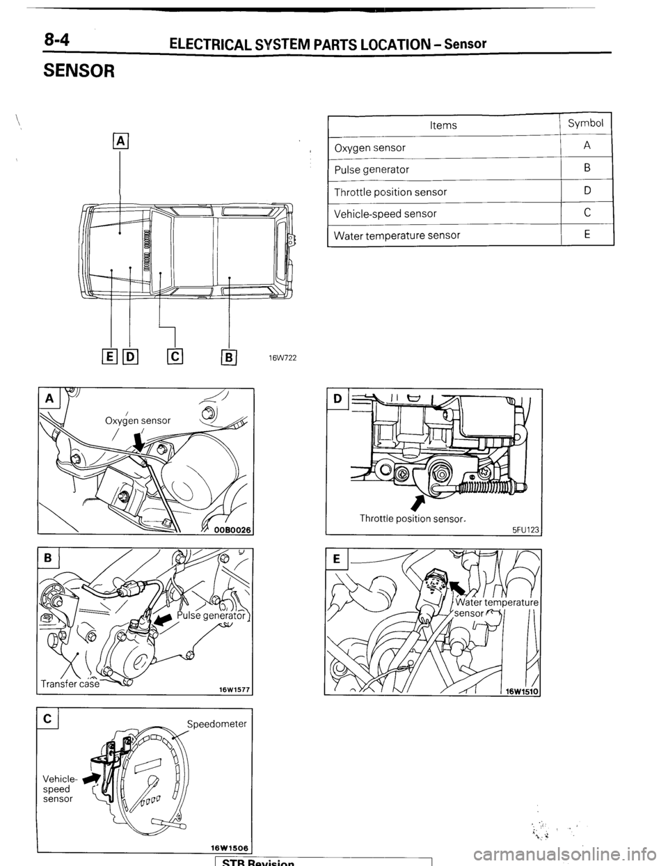
SENSOR ELECTRICAL SYSTEM PARTS LOCATION - Sensor
I leedometer
16W1506
p
Items
Oxygen sensor
-
Pulse generator --
Throttle position sensor
_____
Vehicle-speed sensor
~~
Water temperature sensor Symbol
A B
D C
E
ltw722
I Throttle position sensor.
I
Revision
Page 48 of 284

8-28 WIRING HARNESS - Engine Compartment
1 ENGINE COMPARTMENT
Connector symbol
A
;:::I Main fusible link
;:::I 4WD indicator switch
A-05 Automatic transmission oil
temperature switch
A-06 Back-u light and 4WD indicator
A-07)wiring f!arness and cord
assembly combination
;:g> Back-up light switch
A-l 0 OD-OFF solenoid
A-l 1 Pulse generator
A-l 2 Front wiring harness and
transmission wiring harness
combination
A-13 Air conditioner solenoid valve
A-l 4 Front wiper motor A-
A156
A-55
A-l 7 Checker
A-18 Diode
A-19 Brake fluid level sensor
A-20 Front harness and back-up light
A-21 land 4WD indicator wiring
harness combination
it;;> Sub fusible link
A-24 Carburetor assembly
A-25 Control wiring harness and air
conditioner wiring harness
combination
A-26 Front wiring harness and control
wiring harness combination
A-27 Device box A-53 A-52
A-54
A-28 Auto choke relay
A-29 Front wiring harness and air
conditioner wiring harness
combination
A-30 Headlight washer motor
A-31 Front combination light (L.H.)
A-32 Light control relay
A-33 Dedicated fuse (Upper beam
indicator circuit)
A-34 Headlight (L.H.)
A-35 Condenser fan motor
A-40 Condenser fan motor relay
1 STB Revision
Page 49 of 284

WIRING- HARNESS - Engine Compartment 8-29
; A-06 A-08 A-1 0 A-12 A-14
,.
1 A-15 8
I I
,I I I, I /
A-48
WI
&-ii& ’
A-35 Ai34 A!33 J-3:
A-39 A-37
36W618
A41
i-$ Ignition coil
A-44
A-45 Magnetic clutch
A-46 Water temperature sensor (FBC circuit)
;rii}Alternator
A-49 Water temperature switch (Air conditioner circuit)
A-50 Water temperature gauge unit
A-51 Water temperature switch (OD control circuit)
A-52 Oil pressure gauge or oil pressure switch
$3 Low pressure switch A-55 Headlight (R.H.)
A-56 Front harness and air conditioner wiring harness
combination
A-57 Front combination light (R.H.)
A-58 Front washer motor
A-59 Oxygen sensor
Remarks
(1) The mark * shows the reference mounting position of
wiring harness.
(2) For information concerning the ground points (exam-
ple:
q ), refer to P.8-7.
1 STB Revision
Page 59 of 284

WIRING HARNESS - Feed Back Carburetor Circuit 8-39
Ignition
coil
) _ ,E3
$-To vacuum solenoid valve [Refer to P.8-57.1
7 A-42
cl BR
q A-4
c-2
, 0.85-BW
I YG
I ;
I : YL.
I
I ;
RW,
I :
‘A
f
r
A-4
A-9
A-3
A-6
A-5
B-l 1
B-6
B-9
B-IO Feed back
carburetor
control unit
I
II
II
(I I
1 I ! ! I I- - - - -. -_ __ __
L---- __._._
I +L----J I i-----,
B
B-l
B-2
B-l 2
B-3
B-13
B-8
B-7
B-5
A-46 Vacuum switch
Device
box
control solenoid
L
L
Water
temperature
sensor 1 STB Revision
Page 60 of 284

8-40 WIRING HARNESS - Layout of Components WC)
LAYOUT OFCOMPONENJS [FBC)
CD
II A
5FU131
Items
Symbol Items Symbol
Auto choke relay J Slow-cut solenoid valve D
Engine speed sensor (Ignition coil 0)
Feed back carburetor control unit G
Throttle opener control solenoid valve (for the
A
K air-conditioner)
Feed back solenoid valve
I
C Throttle position sensor
I E
Oxygen sensor
I H Vacuum switch
I F
Secondary air control solenoid valve
I I 1 Water temperature sensor
I B
Throttle opener contr
solenoid valve