Page 1719 of 1865
15 POWER WINDOW
76G15X-013
76G15X-014
15-64
Page 1720 of 1865

POWER WINDOW 1 5
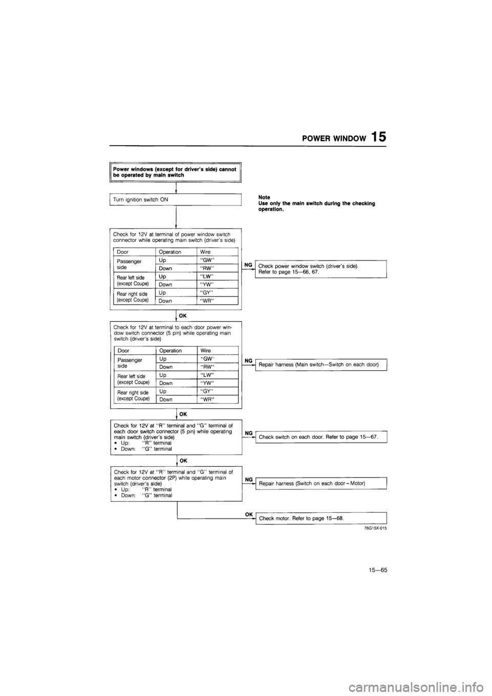
Power windows (except for driver's side) cannot be operated by main switch
Turn ignition switch
ON Note
Use only the main switch during the checking operation.
Check
for
12V
at
terminal
of
power window switch connector while operating main switch (driver's side)
Door Operation Wire
Passenger
side
Up "GW" Passenger
side Down "RW"
Rear left side
(except Coupe)
Up "LW" Rear left side
(except Coupe) Down "YW"
Rear right side
(except Coupe)
Up "GY" Rear right side
(except Coupe) Down "WR"
NG
Check power window switch (driver's side). Refer
to
page 15—66,
67.
OK
Check
for
12V
at
terminal
to
each door power win-dow switch connector
(5
pin) while operating main switch (driver's side)
Door Operation Wire
Passenger Up "GW"
side Down "RW"
Rear left side Up "LW"
(except Coupe) Down "YW"
Rear right side Up "GY"
(except Coupe) Down "WR"
Repair harness (Main switch—Switch
on
each door)
OK
Check
for
12V
at
"R" terminal and
"G"
terminal
of
each door switch connector
(5
pin) while operating main switch (driver's side)
•
Up: "R"
terminal
• Down:
"G"
terminal
NG
Check
for
12V
at
"R" terminal and
"G"
terminal
of
each door switch connector
(5
pin) while operating main switch (driver's side)
•
Up: "R"
terminal
• Down:
"G"
terminal
NG
Check switch
on
each door. Refer
to
page 15—67.
Check
for
12V
at
"R" terminal and
"G"
terminal
of
each door switch connector
(5
pin) while operating main switch (driver's side)
•
Up: "R"
terminal
• Down:
"G"
terminal
OK
76G15X-015
15—65
Page 1721 of 1865
15 POWER WINDOW
OK Check power window switch
on
each door. Refer
to
page 15—67.
76G15X-059
INSPECTION
Power Window Driver's Side Switch
(For Sedan and Hatchback)
Check for continuity between terminals of the switch.
Main switch
—Terminal Position -——___ h i
Lock
Unlock
O o
O O:
Indicates continuity
76G15X-016
c f i i 0
b e h k n
a d R J m /
O O:
Indicates continuity
15-66
Page 1722 of 1865
REAR WINDOW 15
9 c a
CD [=• cm
•
h f d b
76G15X-017
g c a
I I I I
cm I I I I
h f d b
86U15X-11E
(For Coupe/MX-6)
Check for continuity between terminals of the switch.
Main switch
-—-—^^Terminal Position
——- ^
a c
Lock
Unlock 0 O
o
-O: Indicates continuity
Switch
'erminal
Position
UP
OFF
DOWN
Driver's side
O
O
o
o-
o
-o
-o
-o
=o
-o
Passenger's side
O
O
O-
O
O
-o
-o
-o
-o
-o
O O:
Indicates continuity
Switch on Each Side
(For Sedan And Hatchback)
Check for continuity between terminals of the switch.
Position Terminal
UP
OFF
DOWN
O-
O-
O-
-0
O-
O-
-o
-o -o
-o
O O:
Indicates continuity
(For Coupe/MX-6)
Check for continuity between terminals of the switch.
Position
~———^
a b d f h
UP O—
O— —0
—o
OFF o—
O—
—o —O
DOWN O—
o—
—0 —o
O
O:
Indicates continuity
76G15X-019
15-67
Page 1723 of 1865
15 POWER WINDOW
15-68
Power Window Motor
1. Connect 12V to the "a" terminal and ground the
"b" terminal of the motor connector, and check
that the motor operates.
2. Reverse the above connections and check for re-
verse operation of the motor.
Page 1726 of 1865
REAR WINDOW WIPER 15
REAR WINDOW WIPER
STRUCTURAL VIEW
1. Wiper arm and blade
2. Seal cap
86U15X-126
3. Wiper motor
4. Washer tank and motor
5. Hose
6. Washer nozzle
15—71
Page 1727 of 1865
15 REAR WINDOW WIPER
CIRCUIT DIAGRAM
BATTERY MAIN FUSE X-01
X-01
REAR WIPER
&
WASHER SW GW [!]>• Control (Sectin Eb)
To Instrument Panel Light
D-01 Combination Sw [D]
LO
L B ±±±
LW
LB LR
D-02 Front Wiper Motor [F]
B
LR
LW
±±±
L LB L
D-03 Rear Wiper Sw [I] x
x GW
\±U±±
TTTT
(5 Door)
B
L BL
D-04 Rear Wiper Motor [R3]
^bGL (5Door)
D-05 Rear Washer Motor 1 D-06 Headlight Cleaner Sw
[
LY
RB
(5 Door)
LW GW
C-05 Washer Motor Assembly |Fj
LW
LY L
©I®T
T
LO
15-72
86U15X-127
Page 1728 of 1865
REAR WINDOW WIPER
15
TROUBLESHOOTING
76G15X060
76G15X-061
15—73