Page 1794 of 1865

OUTLINE 16
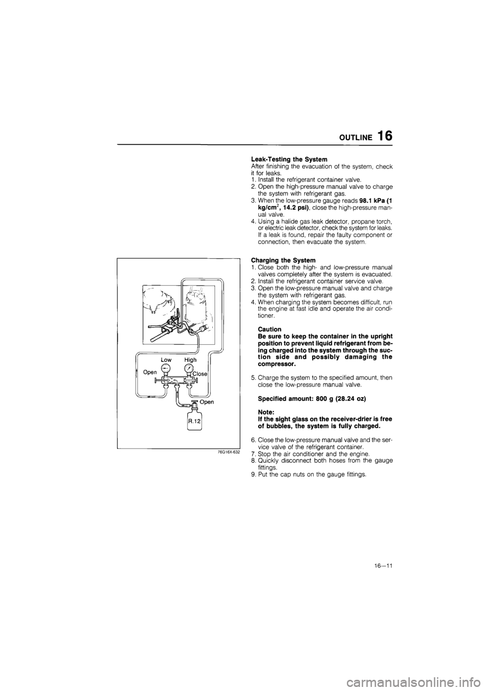
Leak-Testing the System
After finishing the evacuation of the system, check
it for leaks.
1. Install the refrigerant container valve.
2. Open the high-pressure manual valve to charge
the system with refrigerant gas.
3. When the low-pressure gauge reads 98.1 kPa (1
kg/cm2, 14.2 psi), close the high-pressure man-
ual valve.
4. Using a halide gas leak detector, propane torch,
or electric leak detector, check the system for leaks.
If a leak is found, repair the faulty component or
connection, then evacuate the system.
76G16X-632
Charging the System
1. Close both the high- and low-pressure manual
valves completely after the system is evacuated.
2. Install the refrigerant container service valve.
3. Open the low-pressure manual valve and charge
the system with refrigerant gas.
4. When charging the system becomes difficult, run
the engine at fast idle and operate the air condi-
tioner.
Caution
Be sure to keep the container in the upright
position to prevent liquid refrigerant from be-
ing charged into the system through the suc-
tion side and possibly damaging the
compressor.
5. Charge the system to the specified amount, then
close the low-pressure manual valve.
Specified amount: 800 g (28.24 oz)
Note:
If the sight glass on the receiver-drier is free
of bubbles, the system is fully charged.
6. Close the low-pressure manual valve and the ser-
vice valve of the refrigerant container.
7. Stop the air conditioner and the engine.
8. Quickly disconnect both hoses from the gauge
fittings.
9. Put the cap nuts on the gauge fittings.
16—11
Page 1828 of 1865

30 TECHNICAL DATA
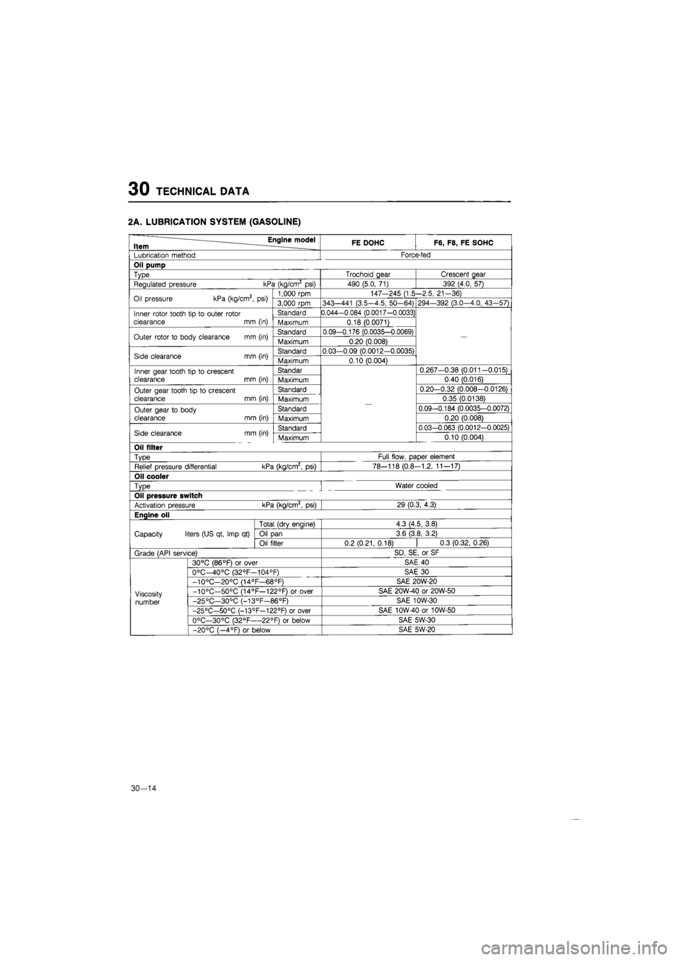
2A. LUBRICATION SYSTEM (GASOLINE)
Engine model Item ____ FE DOHC F6, F8, FE SOHC
Lubrication method Force-fed
Oil pump
Type Trochoid gear Crescent gear
Regulated pressure kPa (kg/cm2
psi)
490 (5.0,
71)
392 (4.0, 57)
Oil pressure kPa (kg/cm2,
psi)
1,000 rpm 147-245 (1.5-2.5, 21-36) Oil pressure kPa (kg/cm2,
psi)
3,000
rpm
343—441 (3.5-4.5, 50-64) 294—392 (3.0—4.0, 43-57)
Inner rotor tooth
tip to
outer rotor
clearance
mm
(in)
Standard 0.044-0.084 (0.0017-0.0033)
—
Inner rotor tooth
tip to
outer rotor
clearance
mm
(in) Maximum 0.18 (0.0071)
—
Outer rotor
to
body clearance
mm
(in) Standard 0.09-0.176 (0.0035-0.0069)
—
Outer rotor
to
body clearance
mm
(in) Maximum 0.20 (0.008)
—
Side clearance
mm
(in) Standard 0.03-0.09 (0.0012-0.0035)
—
Side clearance
mm
(in) Maximum 0.10 (0.004)
—
Inner gear tooth tip
to
crescent clearance
mm
(in)
Standar
—
0.267-0.38 (0.011-0.015) Inner gear tooth tip
to
crescent clearance
mm
(in) Maximum
—
0.40 (0.016)
Outer gear tooth tip
to
crescent clearance
mm
(in)
Standard
—
0.20-0.32 (0.008-0.0126) Outer gear tooth tip
to
crescent clearance
mm
(in) Maximum
—
0.35 (0.0138)
Outer gear
to
body
clearance
mm
(in)
Standard
—
0.09-0.184 (0.0035-0.0072) Outer gear
to
body
clearance
mm
(in) Maximum
—
0.20 (0.008)
Side clearance mm (in) Standard
—
0.03-0.063 (0.0012-0.0025) Side clearance mm (in) Maximum
—
0.10 (0.004)
Oil filter
Type Full flow, paper element
Relief pressure differential kPa (kg/cm2,
psi)
78-118 (0.8-1.2, 11-17)
Oil cooler
Type
!
Water cooled
Oil pressure switch
Activation pressure kPa (kg/cm2,
psi)
29 (0.3, 4.3)
Enaine oil
Capacity liters (US qt, Imp
qt)
Total (drv enaine) 4.3 (4.5, 3.8)
Capacity liters (US qt, Imp
qt)
Oil
Dan
3.6 (3.8, 3.2) Capacity liters (US qt, Imp
qt)
Oil filter 0.2(0.21,0.18)
|
0.3 (0.32,0.26)
Grade (API service) SD, SE,
or
SF
Viscosity
number
30°C (86°F)
or
over SAE
40
Viscosity
number
0°C—40°C (32°F—104°F) SAE
30
Viscosity
number
-10°C—20°C (14°F—68°F) SAE 20W-20
Viscosity
number
-10°C—50°C (14°F—122°F)
or
over SAE 20W-40
or
20W-50 Viscosity
number -25°C—30°C (-13°F—86°F) SAE 10W-30 Viscosity
number
-25°C—50°C (-13°F—122°F)
or
over SAE 10W-40
or
10W-50
Viscosity
number
0°C—30°C (32°F—22°F)
or
below SAE 5W-30
Viscosity
number
-20°C (—4°F)
or
below SAE 5W-20
30-14
Page 1829 of 1865

TECHNICAL DATA 30
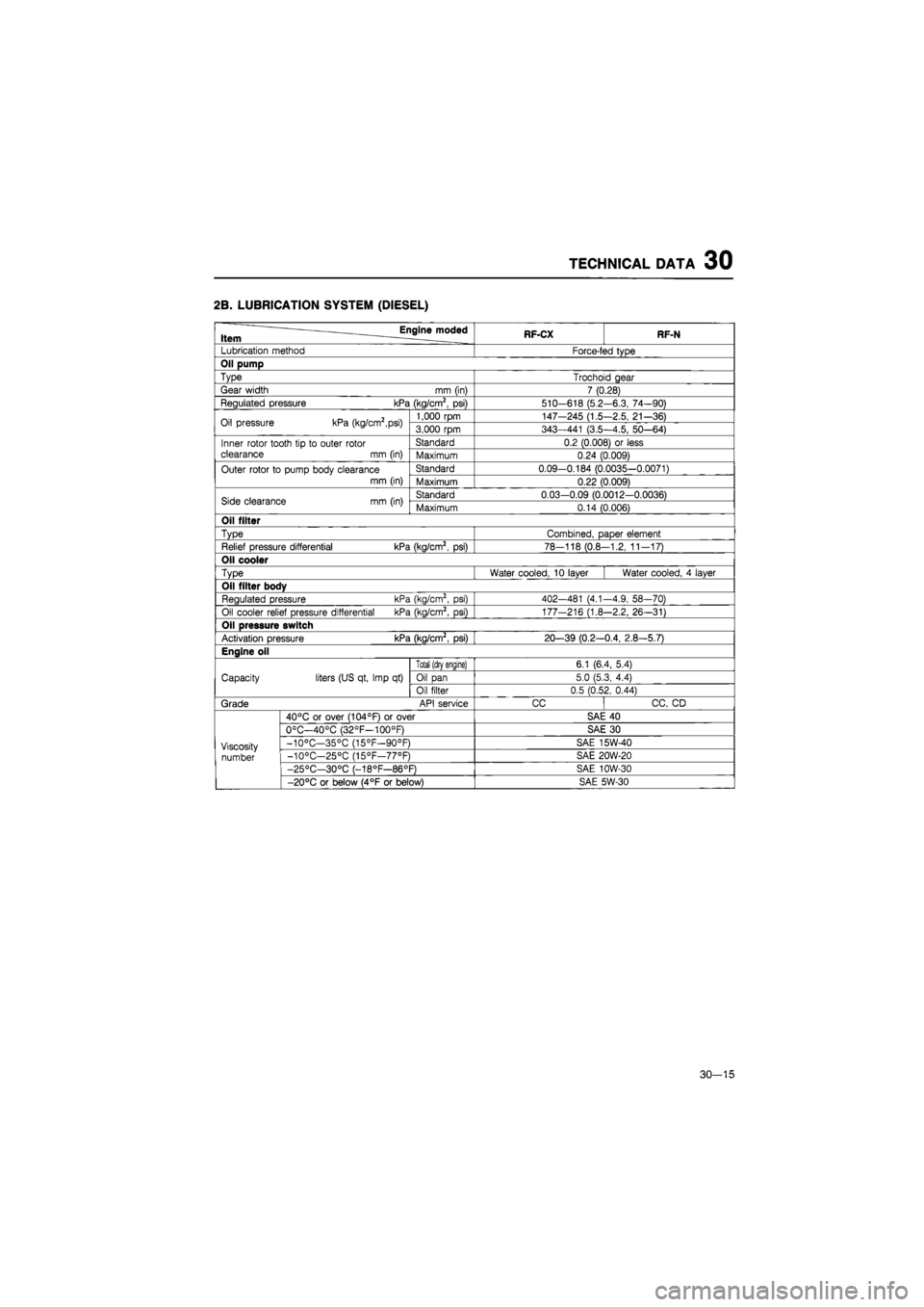
2B. LUBRICATION SYSTEM (DIESEL)
Engine moded Item RF-CX RF-N
Lubrication method Force-fed type
Oil pump
Type Trochoid gear
Gear width
mm
(in) 7 (0.28)
Regulated pressure kPa (kg/cm2,
psi)
510-618 (5.2-6.3, 74-90)
Oil pressure kPa (kg/cm2,psi) 1,000 rpm 147-245 (1.5-2.5, 21-36) Oil pressure kPa (kg/cm2,psi) 3,000 rpm 343—441 (3.5—4.5, 50—64)
Inner rotor tooth
tip to
outer rotor clearance
mm
(in)
Standard 0.2 (0.008)
or
less Inner rotor tooth
tip to
outer rotor clearance
mm
(in) Maximum 0.24 (0.009)
Outer rotor
to
pump body clearance
mm (in)
Standard 0.09-0.184 (0.0035-0.0071) Outer rotor
to
pump body clearance
mm (in) Maximum 0.22 (0.009)
Side clearance
mm
(in) Standard 0.03-0.09 (0.0012-0.0036) Side clearance
mm
(in) Maximum 0.14 (0.006)
Oil filter
Type Combined, paper element
Relief pressure differential kPa (kg/cm2,
psi)
78-118 (0.8-1.2, 11-17)
Oil cooler
Type Water cooled,
10
layer Water cooled,
4
layer
Oil filter body
Regulated pressure kPa (kg/cm2,
psi)
402-481 (4.1-4.9, 58—70)
Oil cooler relief pressure differential kPa (kg/cm2,
psi)
177-216 (1.8-2.2, 26-31)
Oil pressure switch
Activation pressure kPa (kg/cm2,
psi)
20-39 (0.2—0.4, 2.8-5.7)
Engine oil
Capacity liters (US qt, Imp
qt)
Total (drv enaine) 6.1 (6.4, 5.4)
Capacity liters (US qt, Imp
qt)
Oil pan 5.0 (5.3, 4.4) Capacity liters (US qt, Imp
qt)
Oil filter 0.5 (0.52, 0.44)
Grade API service CC CC,
CD
Viscosity number
40°C
or
over (104°F)
or
over SAE
40
Viscosity number
0°C—40°C (32°F—100°F) SAE
30
Viscosity number
-10°C—35°C (15°F—90°F) SAE 15W-40 Viscosity number -10°C—25°C (15°F—77°F) SAE 20W-20 Viscosity number
-25°C—30°C (-18°F—86°F) SAE 10W-30
Viscosity number
-20°C
or
below (4°F
or
below) SAE 5W-30
30—15
Page 1856 of 1865
40 SPECIAL TOOLS
GENERAL INFORMATION
The letters "A" and "B" in the Priority column indicate the degree of importance of each tool.
A Indispensable
The tools ranked "A" in this list are indispensable for performing operations satisfactorily, easily, safe-
ly and efficiently. It would, therefore, be advisable for all service shops to have these tools.
B Selective
The tools in this list are not as necessary as tools ranked A, but all servise shops should have these
tools if possible in order to easily perform operations for efficient repair operations.
86U40X-002
Note
When ordering tool sets which consist of several tools, check the List in the Parts Cata-
logue or Special Service Tools Booklet (4063-11-85B) etc. to make sure that some tools
are duplicated in other sets which may already have been purchased. If so, order only those
new tools which are needed.
73G40X-002
40-2