Page 1638 of 1865
SLIDING SUNROOF 14
76U14X-063
76U14X-064
76U14X-065
8. Install the lower panel and tighten the screws.
9. Install the guide front and tighten the screws.
10. Pull out the drip rail from the rear, and secure the
link by the screw.
11. Using the handle turn the motor to fully open the
lower panel.
Note
a) Because the roof panel and lower panel
might interfere with each other when the
lower panel is opened, check as shown in
the figure, that the guide roller is completely
fitted into the guide rail.
b)Turn the motor while pushing the cable.
12. Secure the deflector by tightening the screw, and
then install the deflector link.
13. Turn the motor using the handle, and visually check
the sliding, tilt-down and tilt-up operations.
76U14X066
14—87
Page 1639 of 1865
1 4 SLIDING SUNROOF
76U14X-067
Set plate
76U14X-068
1.5mm (0.016 in)
: ? ©—
A-A Cross section
76U14X-069
B-B Cross section
Adjust screw Fitting screw jj
Fitting screw®
14. Fully close the lower panel.
15. Install the slide panel to the lower panel, and tight-
en securely.
16. Insert the sun shade from the notch in the set plate,
and push it all the way back.
17. Insert the set plate cap.
18. Adjust the height of the slide panel.
(Cross-section A-A)
Adjust so that the height difference between the
outer panel and roof panel is 1.5 mm (0.06 in)
max.
(Cross-section B-B adjustment)
(1) Loosen installation screws (1) and (2).
If the adjustment is only about 2 mm (0.08 in)
don't loosen screw (1).
(2) Turn the screws to adjust.
Turning to the right raises, and to the left lowers.
(3) Tighten installation screws (1) and (2).
76U14X-070
14-88
Page 1640 of 1865

SLIDING SUNROOF 14
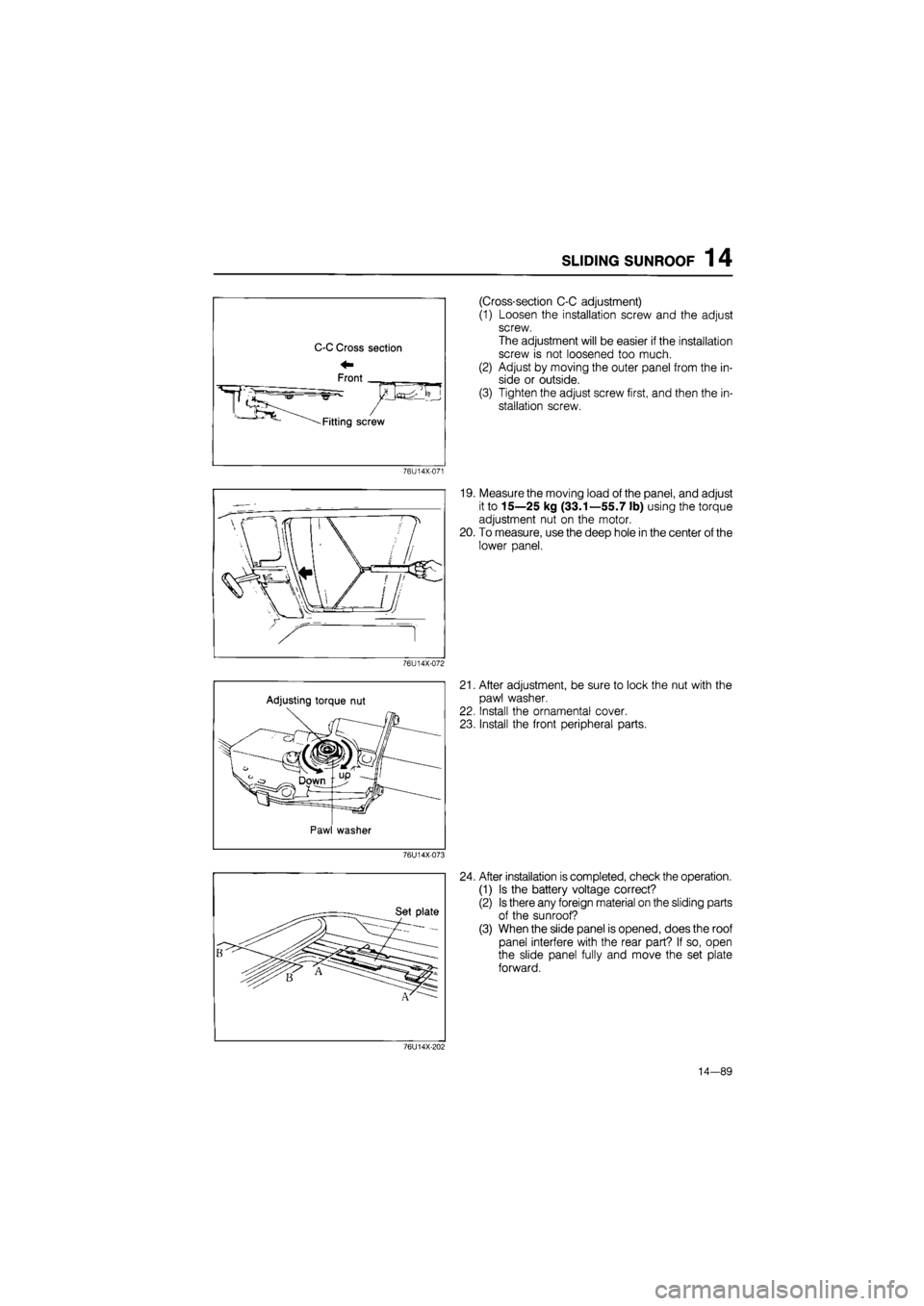
(Cross-section C-C adjustment)
(1) Loosen the installation screw and the adjust
screw.
The adjustment will be easier if the installation
screw is not loosened too much.
(2) Adjust by moving the outer panel from the in-
side or outside.
(3) Tighten the adjust screw first, and then the in-
stallation screw.
76U14X-071
19. Measure the moving load of the panel, and adjust
it to 15—25 kg (33.1—55.7 lb) using the torque
adjustment nut on the motor.
20. To measure, use the deep hole in the center of the
lower panel.
76U14X-072
Adjusting torque nut
Pawl washer
21. After adjustment, be sure to lock the nut with the
pawl washer.
22. Install the ornamental cover.
23. Install the front peripheral parts.
76U14X-073
24. After installation is completed, check the operation.
(1) Is the battery voltage correct?
(2) Is there any foreign material on the sliding parts
of the sunroof?
(3) When the slide panel is opened, does the roof
panel interfere with the rear part? If so, open
the slide panel fully and move the set plate
forward.
76U14X-202
14—89
Page 1641 of 1865
1 4 SLIDING SUNROOF
5 mm (0.20 in) o p Front
IP
i^ : • 1
B-B Cross section
A-A Cross section
76U14X-203
Caution:
If the stopper is moved too far forward, there
might be a malfunction or leaking. Do not
leave a gap of more than 5 mm (0.2 in) be-
tween the slide panel and roof panel.
14—90
Page 1656 of 1865

15
BODY ELECTRICAL SYSTEM
INTRODUCTION 15- 2 HOW TO USE THIS SECTION 15— 2 ELECTRICAL TROUBLESHOOTING TOOLS 15- 2 PRECAUTION 15— 3 ELECTRICAL SYMBOLS 15- 6 LOCATION OF UNIT, RELAY AND SWITCH 15- 7
STRUCTURAL VIEW 15— 7 MAIN FUSE BLOCK 15- 9 STRUCTURAL VIEW 15— 9 REPLACEMENT 15—10 IGNITION SWITCH 15—10
INSPECTION 15— 10 JOINT BOX AND FUSE 15—11
STRUCTURAL VIEW 15—11
COMBINATION SWITCH 15-12 STRUCTURAL VIEW 15- 12 INSPECTION 15— 13 CLUSTER SWITCH 15—17 STRUCTURAL VIEW 15— 17 INSPECTION OF ROCKER TYPE 15— 19
INSPECTION OF PUSH TYPE 15— 20 METER 15— 22 STRUCTURAL VIEW 15— 22 DISASSEMBLY AND ASSEMBLY 15— 23
TROUBLESHOOTING 15— 24 INSPECTION OF ANALOG METER .... 15— 26 INSPECTION OF DIGITAL METER 15— 27
INSPECTION OF METER SENDER 15— 29 WARNING LIGHT AND SENDER 15- 31 CIRCUIT DIAGRAM 15— 31
TROUBLESHOOTING 15- 32 INSPECTION 15— 39 CENTRAL PROCESSING UNIT 15— 41 STRUCTURAL VIEW 15— 41 FUNCTIONS 15- 41 CIRCUIT DIAGRAM 15— 42 REMOVAL AND INSTALLATION 15— 43
ON-VEHICLE INSPECTION 15- 43 TURN AND HAZARD LIGHT 15- 44 STRUCTURAL VIEW 15— 44 CIRCUIT DIAGRAM 15— 45
TROUBLESHOOTING 15- 46 INSPECTION 15— 47 STOP LIGHT 15— 48
STRUCTURAL VIEW 15— 48 CIRCUIT DIAGRAM 15— 49
TROUBLESHOOTING 15- 49 INSPECTION 15- 50 HORN 15— 52 STRUCTURAL VIEW 15— 52 CIRCUIT DIAGRAM 15— 52 TROUBLESHOOTING 15— 53 INSPECTION 15-53 HEADLIGHT 15— 54 CIRCUIT DIAGRAM 15— 54 TROUBLESHOOTING 15— 54 INSPECTION 15— 55 PANEL LIGHT CONTROL 15— 56 CIRCUIT DIAGRAM 15— 56
TROUBLESHOOTING 15_ 5fi INSPECTION 17 REAR WINDOW DEFROSTER ..i".'! 15- 58
STRUCTURAL VIEW 15-5fl CIRCUIT DIAGRAM 15_ «
TROUBLESHOOTING '.. 15_ 59
INSPECTION
15-60 POWER WINDOW 15-61 STRUCTURAL VIEW il_ «1 CIRCUIT DIAGRAM 15_ 62 TROUBLESHOOTING 15- «3 INSPECTION 15-66 REMOTE CONTROL MIRROR ........15- 69 STRUCTURAL VIEW 15-69 CIRCUIT DIAGRAM 15_ 69
TROUBLESHOOTING 15_ 70 INSPECTION 15_ 70 REAR WINDOW WIPER 15_ 71 STRUCTURAL VIEW 15-71 CIRCUIT DIAGRAM .'.'.'...' 15_ 72
TROUBLESHOOTING 15-73 INSPECTION 15-75 WINDSHIELD WIPER 15-76 STRUCTURAL VIEW ' ' 15— 7e
DISASSEMBLY AND ASSEMBLY OF WIPER MOTOR 15_ 76 CIRCUIT DIAGRAM 15-77 TROUBLESHOOTING " " 15— 70 INSPECTION 15-81 CRUISE CONTROL SYSTEM 15- 82 STRUCTURAL VIEW 15-82 CIRCUIT DIAGRAM 15-83 ON-VEHICLE INSPECTION \..\m 15- 84 INSPECTION 15-87 SLIDING SUNROOF 15-89 STRUCTURAL VIEW 15_ 89 CIRCUIT DIAGRAM i5_ 90
TROUBLESHOOTING 15— 91 INSPECTION 15_ 90 AUTO ADJUSTING SUSPENSION 15— 94
CIRCUIT DIAGRAM 15- 94
TROUBLESHOOTING GUIDE 15— 94
TROUBLESHOOTING 15— 94
INSPECTION 15-104
POWER DOOR LOCK 15-105
STRUCTURAL VIEW 15-105
CIRCUIT DIAGRAM 15-105
TROUBLESHOOTING 15-106 INSPECTION 15-107 AUDIO SYSTEM " 15_108 OUTLINE OF AUDIO SYSTEM 15-108 REAR CONNECTOR VIEW 15-109 ADJUSTMENT (MTR) 15—114 POWER ANTENNA 15-114 HEATER J
STRUCTURAL VIEW 15-116 AIR FLOW AT EACH MODE 15-117 RATE OF AIR FLOW 15-119 LEVER CONTROL TYPE 15-120 LOGICAL CONTROL
TYPE
15—121 LOGICON SWITCH 15—123
76G15X-001
Page 1666 of 1865

JOINT
BOX AND FUSE
1
5
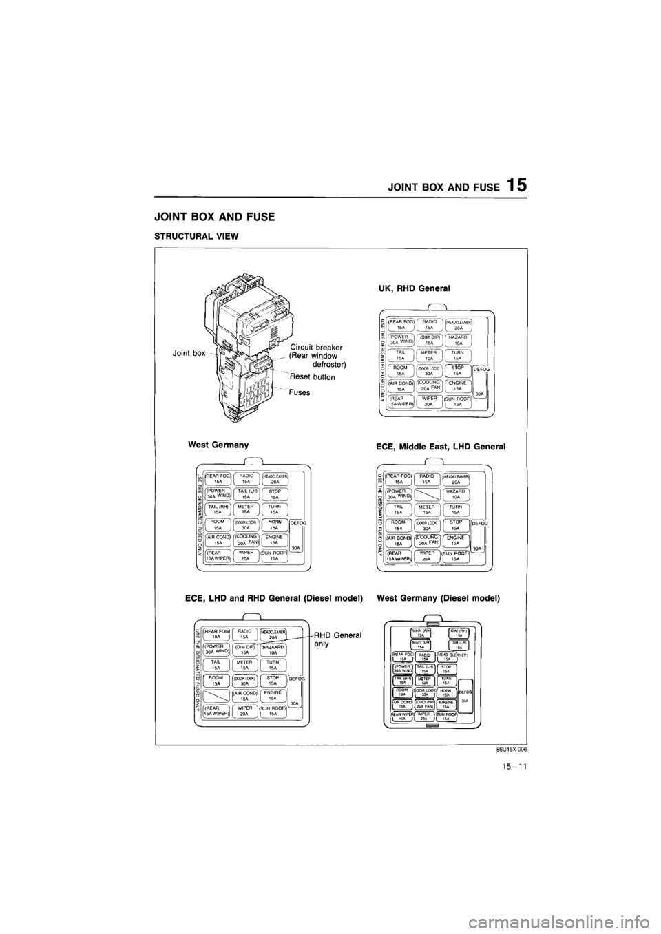
JOINT BOX AND FUSE
STRUCTURAL VIEW
Joint box Circuit breaker
(Rear window
defroster)
Reset button
Fuses
West Germany
(REAR FOG* RADIO 15A 15A (HEADCLEANER) 20A
(POWER 30A WIND) TAIL (LH) 15A STOP 15A
TAIL (RH) 15A METER 15A TURN 15A
ROOM 15A f(D00R LOCK) [ 30A c
HORN 5A
(AIR COND)' 15A (COOLING 20A FAN>I ENGINE 15A
(REAR 15A WIPER) WIPER 20A (SUN ROOF) [ 15A
ECE, LHD and RHD General (Diesel model)
. Q .
(REAR FOG) 15A J RADIO 15A (rHEADCLEAMEfii I joa J (POWER 1 30A WIND)j (DIM DIP) 15A ( HAZAARD ' I TAIL 15A METER 15A TURN 15A
' ROOM ' ISA j flBOOR LOCKl"1 L STOP 1SA -[(AIR COND) 15A J ' ENGINE 15A
(REAR 15A WIPER) WIPER 20A (SUN ROOF) I 16A
RHD General
only
UK, RHD General
(REAR FOG)
[
15A J
RADIO 15A (HEADCLEANER) 20A
(POWER 30A WIND) (DIM DIP) 15A HAZARD 10A
TAIL 15A METER 10A TURN 15A
ROOM 15A (DOOR LOCK) 30A STOP 15A
(AIR COND) 15A '(COOLING 20A FAN) ENGINE 15A
(REAR 15A WIPER) WIPER 20A (SUN ROOF) [ 15A ,
ECE, Middle East, LHD General
Q
(REAR FOG) 15A J RADIO 15A (HEADCLEANER) 20A
(POWER 30A WIND) HAZARD 10A
TAIL 15A METER 15A TURN 15A
ROOM 5A (DOOR LOCK) 3CA STOP tSA ] (AIR CONO)| . ISA jj| ((COOLING! ( ENGINE 1 J [
BOA
FAfJ)J [ 15A J
(REAR 15AWIP£R), ^ C WIPER "1[SUN HOOF?
1)J
[ 2QA
J
[ 15A
West Germany (Diesel model)
MAIN (fWl
ISA I
MALM (LM1
15A
DIM iLHI
ISA
PEAfl FOCii
I 'SA | RAQIO T5A I
HEAP CLEANEF*
1 I (POWEfl I
3PA WI^D;. TAIL (LH)
15A
)C
TAIL
I ISA METER 1OA TURN 15A FIOQM
(DOOR LOC*C|
HOflN 15A Jt 1SA
(
AIR COND)
jy (COOUNQ
gqA FAN)
ENGINE 16A
|fl£AR WlPEFl!
ILJSi '
DEfOO
3 OA
Dtf
WtPEfl
USUNROQF Jl JPA H 15A [
86U15X-006
15-11
Page 1744 of 1865
SLIDING SUNROOF 1 5
SLIDING SUNROOF
STRUCTURAL VIEW
86U15X-148
1. Slide panel
2. Deflector assembly
3. Motor assembly
4. Guide bracket
5. Driving cable
6. Guide bracket assembly rear
7. Tilt up switch
8. Slide switch
15—89
Page 1745 of 1865
1 5 SLIDING SUNROOF
CIRCUIT DIAGRAM
BATTEHY
© © P o-
B
[Fj -
80A
X-01
ff
WR [F] X-01 MAIN
X-06
FUSE
X-ffij
4 |
-WR [D]-
JB-09
©
Hit
LR
R|
LR [Fr) REAR HATCH
^T-06 T-06
BlFrj
Bl
i iii
-LR [In] -
15®
— JB-IO ® ROOM
^JB-03(
[
B[D| i
-J1
Unleaded Fuel (Except Sweden & West Germany)
X-D2
IGN SW
VX-OZ
BW |D|
r-oe T-01 JB-10 © 5SA@ ^JB-07®
= = = = = ^ T-05
BrW"|Frj RW IFi]
^ X-jfi
RW [R]
BrW'[H2| RW [R2|
LR
T-04
SUNROOF REUY No.1
I fp LW-' ly
4f - = - --
LW
S.G LY
REAR HATCH MOTOR
T-01 Connector Between Interior Light Harness [In] and Sunroof
T-02 Sunroof Sw
LG
LW G (±±±
B
l. LY
GO
LW LG ±±±
LY
L B
T-03 Sunroof Motor
Y
L LY YG
pL=LX Jh
TTTT1
YR
B
LG LW
YG
LY L Y
Ntttt) TTTT
LW LG
B YR
T-04 Sunroof Relay No
1
G
Y G
r±±±-
B
« L
T-05 Sunroof Relay No
2
G
YR G
B
x YG
T-06 Rear Hatch Sw
|
BrW
B
LR
RW
5 Door
T-07 Rear Hatch Motor [R3] RW
*
B;W
*
15-90
86U15X-149