Page 1752 of 1865
AUTO ADJUSTING SUSPENSION (AAS) 1 5
C
(Cont'd)
Operate
the
vehicle
at
above
15 km/h (9.3
mph) on
a
chassis roller
OV-
4.4V
0V-
4.4V
OV-
OV
AAS switch
or
wiring har-
ness (Fuse box
—
Control
box and AAS switch, AAS
switch
—
Control box and
Body ground)
Normal operation
Speed sensor
or
Steering
wheel angle sensor
or
wir-
ing harness (Control unit
—
Meter, Control unit
—
An-
gle sensor)
Speed sensor
or
Wiring
harness (Control unit
—
Meter, Fuse box
—
Control
unit, Control unit
—
Body
ground)
76G15X-080
15-97
Page 1754 of 1865
AUTO ADJUSTING SUSPENSION
(AAS) 1 5
AAS-3
Normal operation
or
failure
of
the wir-ing harness (Fuse box
to
Control unit, Control unit
to
Body ground)
Check the voltage between each terminal
of
the con-trol unit connector and
a
body ground with ignition ON.
Terminal Voltage
G(B) OV
J(B) OV
K (BY) Approx.
12V
OK
Normal operation.
NG
Replace TURN 15A fuse
or
repair the wiring harness (Fuse box
to
Control unit, Control unit
to
Body ground.)
86U15X-161
AAS-4
Failure
of
wiring harnesses (Fuse
box
to Control unit, Control unit
to
Body
ground).
Check the voltage between each terminal
of
control unit connector and
a
body ground with ignition
ON.
Terminals Voltage
G (B) OV
J (B) OV
K (BY)
ADDTOX.
12V
OK
Replace the control unit.
NG
Replace TURN 15A fuse
or
repair the wiring harness-
es (Fuse box
to
Control unit, Control unit
to
Body
ground.)
86U15X-162
15-99
Page 1755 of 1865

1 5 AUTO ADJUSTING SUSPENSION (AAS)
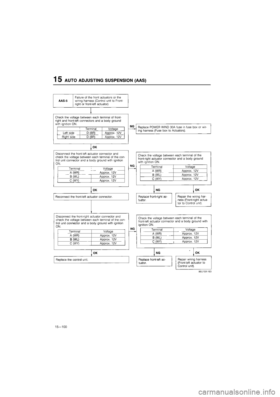
AAS-5
Failure
of
the front actuators
or the
wiring harness (Control unit
to
Front-right
or
front-left actuator)
Check the voltage between each terminal
of
front-right and front-left connectors and
a
body ground with ignition ON.
Terminal Voltage
Left side D (BR) Approx.
12V
Right side D (BR) Approx.
12V
NG
Replace POWER WIND 30A fuse
in
fuse box
or
wir-ing harness (Fuse box
to
Actuators).
OK
Disconnect the front-left actuator connector
and
check the voltage between each terminal
of
the con-trol unit connector and
a
body ground with ignition ON.
Terminal Voltage
A (WR) Approx.
12V
B (WL) Approx.
12V
C (WY) Approx.
12V
NG
OK
Reconnect the front-left actuator connector.
Disconnect the front-right actuator connector and check the voltage between each terminal
of
the con-trol unit connector and
a
body ground with ignition ON.
Terminal Voltage
A WR) Aoorox.
12V
B (WL) ADDrox.
12V
C (WY) Approx.
12V
Check the voltage between each terminal
of the
front-right actuator connector and
a
body ground with ignition
ON.
Terminal Voltage
A (WR) Approx.
12V
B (WL) Approx.
12V
C (WY) Approx.
12V
NG
Replace front-right
ac-
tuator.
OK
Repair the wiring har-ness (Front-right actua-tor
to
Control unit).
NG
Check the voltage between each terminal
of
the
front-left actuator connector and
a
body ground with
ignition ON.
Terminal Voltage
A (WR) Approx.
12V
B (WL) Approx.
12V
C (WY)
|
Approx.
12V
OK
Replace the control unit.
NG OK
Replace front-left
ac-
tuator.
Repair wiring harness (Front-left actuator
to
Control unit).
86U15X-163
15-100
Page 1756 of 1865

AUTO ADJUSTING SUSPENSION (AAS) 1 5
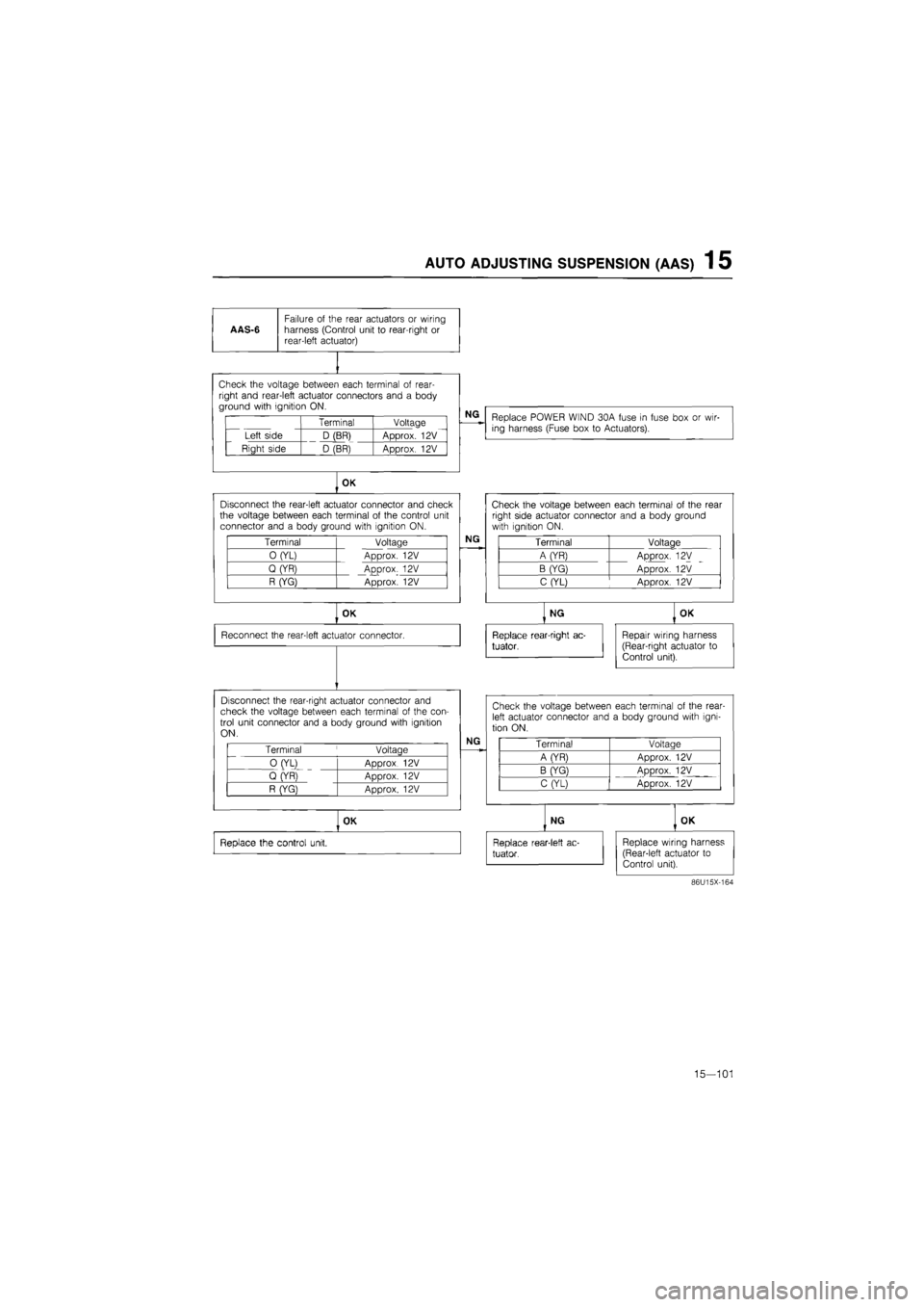
AAS-6
Failure
of
the rear actuators
or
wiring harness (Control unit
to
rear-right
or
rear-left actuator)
vi i11 1vuuuyu tw/v^ii I^CI^I i id i i in I«I wi i
right and rear-left actuator connectors and
a
body ground with ignition ON.
Terminal Voltage
Left side D (BR) Approx.
12V
Right side D (BR) Approx.
12V
NG
Replace POWER WIND 30A fuse
in
fuse box
or
wir-ing harness (Fuse box
to
Actuators).
OK
Disconnect the rear-left actuator connector and check the voltage between each terminal
of
the control unit connector and
a
body ground with ignition ON.
Terminal Voltage
0 (YL) Approx.
12V
Q (YR) Approx.
12V
R (YG) Approx.
12V
NG
OK
Reconnect the rear-left actuator connector.
Disconnect the rear-right actuator connector and check the voltage between each terminal
of
the con-trol unit connector and
a
body ground with ignition ON.
Terminal
'
Voltage
0 (YL)
ADDrox 12V
Q (YR)
ADDrox. 12V
R (YG} Approx.
12V
NG
OK
Replace the control unit.
Check the voltage between each terminal
of
the rear right side actuator connector and
a
body ground with ignition ON.
Terminal Voltage
A (YR) Approx.
12V
B (YG) Approx.
12V
C (YL) Approx.
12V
NG
Replace rear-right ac-
tuator,
OK
Repair wiring harness (Rear-right actuator
to
Control unit).
Check the voltage between each terminal
of
the rear-left actuator connector and
a
body ground with igni-tion ON.
Terminal Voltaae
A (YR) Approx.
12V
B (YG) ADDrox.
12V
C (YL) Approx.
12V
NG
Replace rear-1 eft
ac-
tuator.
OK
Replace wiring harness (Rear-left actuator
to
Control unit).
86U15X-164
15—101
Page 1757 of 1865

1 5 AUTO ADJUSTING SUSPENSION
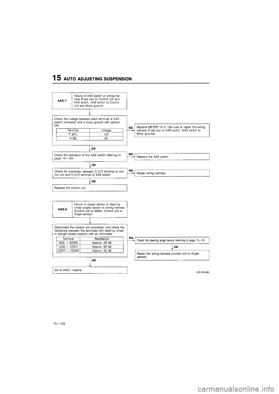
AAS-7
Failure
of
AAS switch
or
wiring har-ness (Fuse box
to
Control unit and AAS switch, AAS switch
to
Control unit and Body ground
Check the voltage between each terminal
of
AAS switch connector and
a
body ground with ignition ON.
Terminal Voltage
F (BY) 12V
H (B) OV
NG Replace METER
10 or
15A fuse
or
repair the wiring harness (Fuse box
to
AAS switch, AAS switch
to
Body ground).
OK
Check the operation
of
the AAS switch referring
to
page 15—104.
, OK
Check
for
continuity, between
D
(LY) terminal
of
con-
trol unit and
D
(LY) terminal
of
AAS switch.
OK
Replace the control unit.
A AS-8
Failure
of
speed sensor
or
steering wheel angles sensor
or
wiring harness (Control unit
to
Meter, Control unit
to
Angle sensor).
NG
Replace the AAS switch.
NG
Repair wiring harness.
Disconnect the control unit connector, and check the resistance between the terminals with steering wheel in straight ahead position with
an
ohmmeter.
Terminal Resistance
A(G)
-
D(GW) Approx.
25
k£2
' A(G}
-
C(GY) Approx.
50 kfl
C(GY)
-
D(GW) Approx.
25
kJ2
NG
Check the steering angle sensor referring
to
page 15—16
OK
Go
to
AAS-1 routine.
OK
Repair the wiring harness (control unit
to
Angle
sensor).
76G15X-083
15-102
Page 1758 of 1865
AUTO ADJUSTING SUSPENSION 1 5
AAS-9
Failure of speed sensor or wiring har-ness (Control unit to Meter, Fuse box to Control unit, Control unit to Body ground)
Replace METER 10 or 15A fuse or repair the wiring harness (Fuse box to Control unit, Control unit to Body ground).
Check the voltage between each terminal of control
unit connector and a body ground with ignition ON.
Terminal Voltage
G (B) OV
J (B) OV
K (BY) Approx. 12V
OK
Go to AAS-1 routine.
76G15X-084
15—103
Page 1761 of 1865
1 5 POWER DOOR LOCK
TROUBLESHOOTING
Terminal Voltage
WG 12V
B OV
Check the voltage
at GB
terminal
of
the power door lock relay with each switch condition.
Terminal Condition Voltage
GB Lock 12V GB Unlock OV
OK
Check the voltage
at R
and
G
terminal
of
the power door lock relay with each switch condition.
Terminal Condition Voltaae
R Lock OV R Unlock 12V
G Lock 12V G Unlock OV
Power door lock does not operate.
Check DOOR LOCK 30A fuse.
OK
NG
Short circuit.
Check the voltage
at
each terminal
of
the power door lock relay connector.
NG
Repair the harness. (Fuse box
to
relay, Relay
to
ground)
OK
Check the power door lock switch. Refer
to
page 15-107.
OK
NG
Replace the switch.
NG
Repair the harness. (Door lock switch
to
relay)
NG
Replace the door lock relay.
OK
Check the power door lock motor. Refer
to
page
15-107.
OK
Repair the harness. (Relay
to
each motors)
NG
Replace the door lock motor.
76G15X086
15—106