1987 MAZDA 626 check engine
[x] Cancel search: check enginePage 1478 of 1865
1 1 ANTI-LOCK BRAKE SYSTEM (ABS)
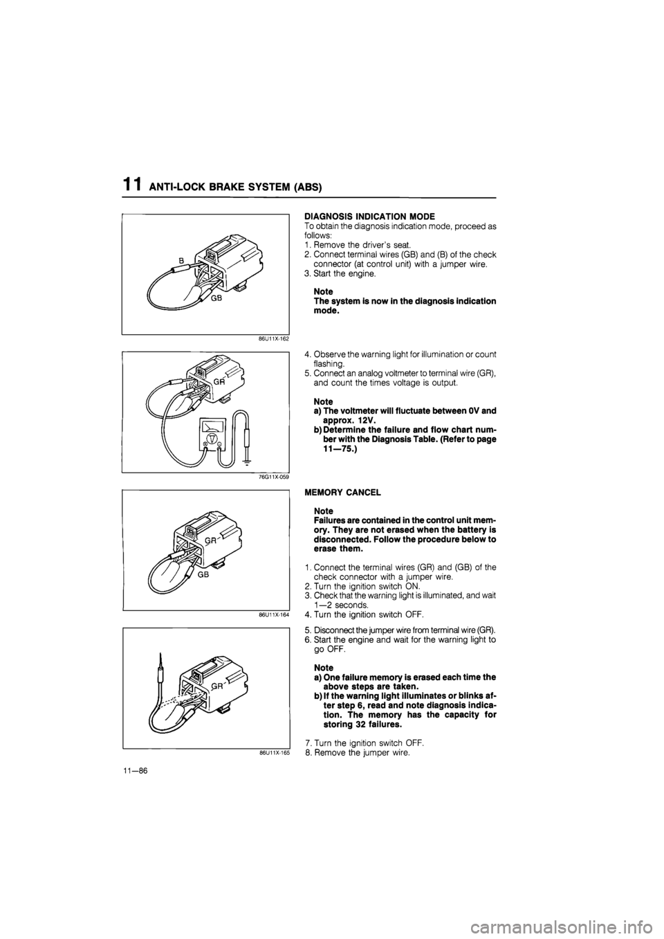
DIAGNOSIS INDICATION MODE
To obtain the diagnosis indication mode, proceed as
follows:
1. Remove the driver's seat.
2. Connect terminal wires (GB) and (B) of the check
connector (at control unit) with a jumper wire.
3. Start the engine.
Note
The system is now in the diagnosis indication
mode.
86U11X-162
4. Observe the warning light for illumination or count
flashing.
5. Connect an analog voltmeter to terminal wire (GR),
and count the times voltage is output.
Note
a) The voltmeter will fluctuate between OV and
approx. 12V.
b) Determine the failure and flow chart num-
ber with the Diagnosis Table. (Refer to page
11—75.)
76G11X-059
86U11X-164
86U11X-165
MEMORY CANCEL
Note
Failures are contained in the control unit mem-
ory. They are not erased when the battery is
disconnected. Follow the procedure below to
erase them.
1. Connect the terminal wires (GR) and (GB) of the
check connector with a jumper wire.
2. Turn the ignition switch ON.
3. Check that the warning light is illuminated, and wait
1—2 seconds.
4. Turn the ignition switch OFF.
5. Disconnect the jumper wire from terminal wire (GR).
6. Start the engine and wait for the warning light to
go OFF.
Note
a) One failure memory is erased each time the
above steps are taken.
b) If the warning light illuminates or blinks af-
ter step 6, read and note diagnosis indica-
tion. The memory has the capacity for
storing 32 failures.
7. Turn the ignition switch OFF.
8. Remove the jumper wire.
11-86
Page 1486 of 1865
1 1 ANTI-LOCK BRAKE SYSTEM (ABS)
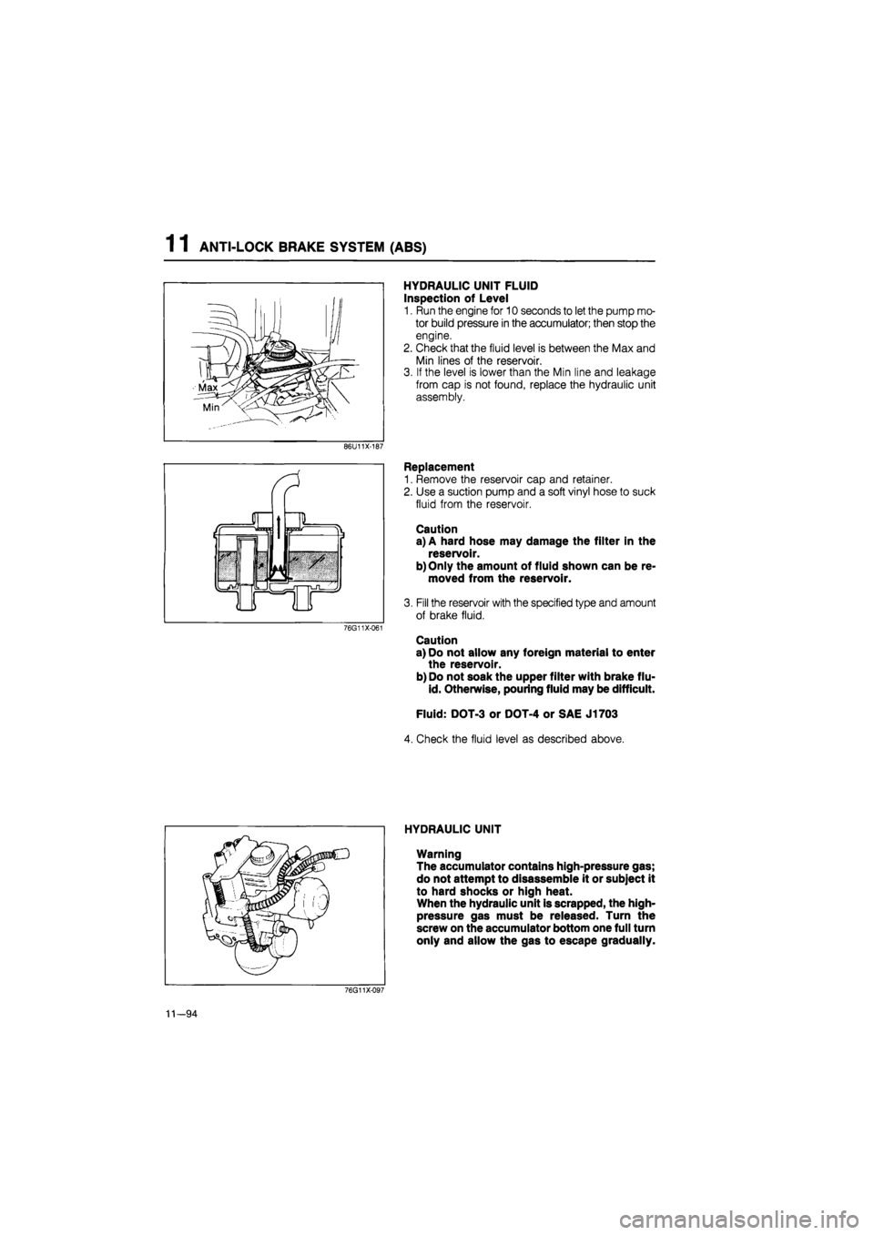
HYDRAULIC UNIT FLUID
Inspection of Level
1. Run the engine for 10 seconds to let the pump mo-
tor build pressure in the accumulator; then stop the
engine.
2. Check that the fluid level is between the Max and
Min lines of the reservoir.
3. If the level is lower than the Min line and leakage
from cap is not found, replace the hydraulic unit
assembly.
86U11X-187
76G11X-061
Replacement
1. Remove the reservoir cap and retainer.
2. Use a suction pump and a soft vinyl hose to suck
fluid from the reservoir.
Caution
a) A hard hose may damage the filter in the
reservoir.
b)Only the amount of fluid shown can be re-
moved from the reservoir.
3. Fill the reservoir with the specified type and amount
of brake fluid.
Caution
a) Do not allow any foreign material to enter
the reservoir.
b) Do not soak the upper filter with brake flu-
id. Otherwise, pouring fluid may be difficult.
Fluid: DOT-3 or DOT-4 or SAE J1703
4. Check the fluid level as described above.
HYDRAULIC UNIT
Warning
The accumulator contains high-pressure gas;
do not attempt to disassemble it or subject it
to hard shocks or high heat.
When the hydraulic unit is scrapped, the high-
pressure gas must be released. Turn the
screw on the accumulator bottom one full turn
only and allow the gas to escape gradually.
76G11X-097
11—94
Page 1487 of 1865
ANTI-LOCK BRAKE SYSTEM (ABS) 1 1
86U11X-190
86U11X-191
76G11X098
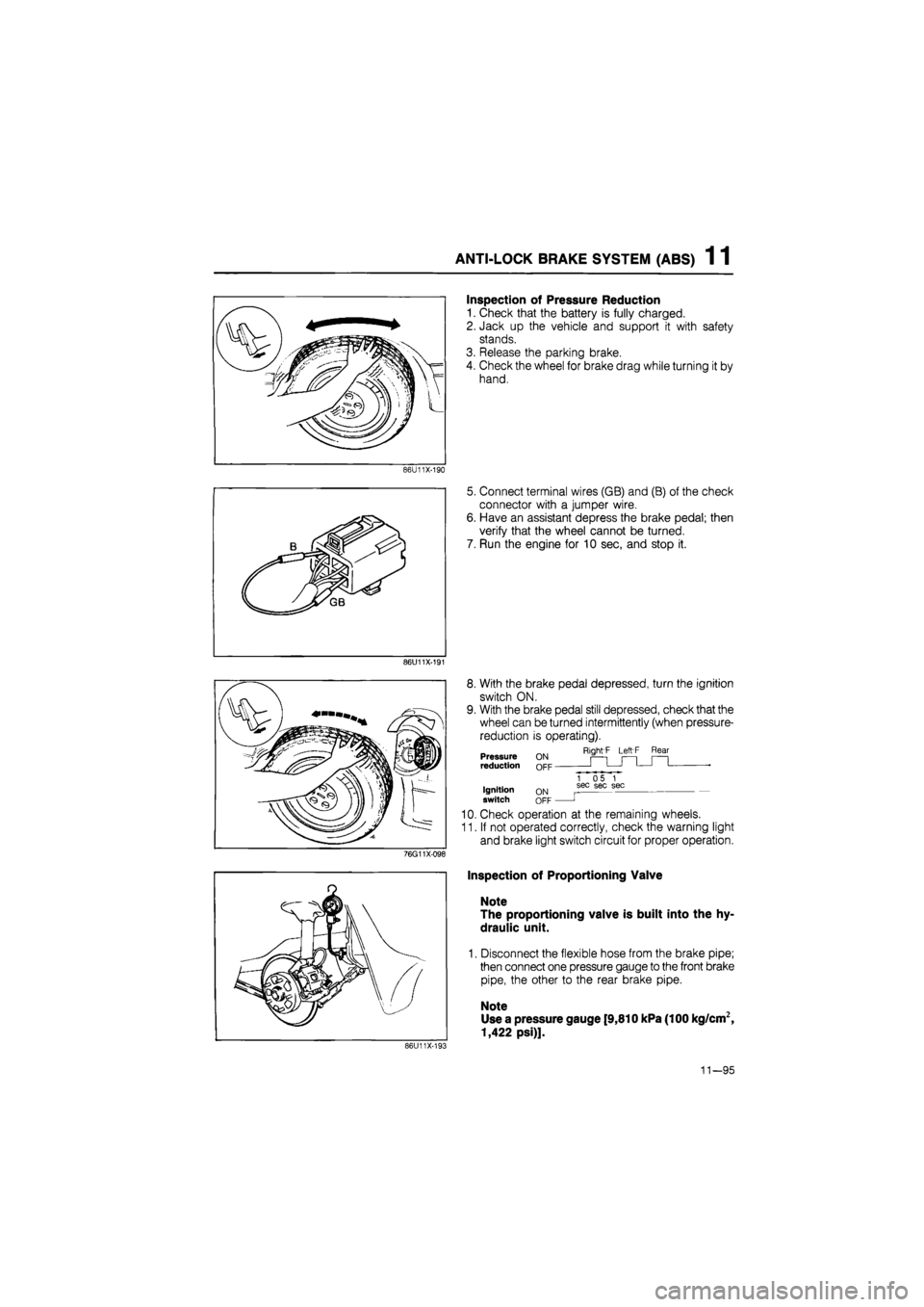
Inspection of Pressure Reduction
1. Check that the battery is fully charged.
2. Jack up the vehicle and support it with safety
stands.
3. Release the parking brake.
4. Check the wheel for brake drag while turning it by
hand.
5. Connect terminal wires (GB) and (B) of the check
connector with a jumper wire.
6. Have an assistant depress the brake pedal; then
verify that the wheel cannot be turned.
7. Run the engine for 10 sec, and stop it.
8. With the brake pedal depressed, turn the ignition
switch ON.
9. With the brake pedal still depressed, check that the
wheel can be turned intermittently (when pressure-
reduction is operating).
Right'F Left F Rear Pressure reduction
Ignition switch ON OFF
1 05 1 sec sec sec
J
10. Check operation at the remaining wheels.
11. If not operated correctly, check the warning light
and brake light switch circuit for proper operation.
Inspection of Proportioning Valve
Note
The proportioning valve is built into the hy-
draulic unit.
1. Disconnect the flexible hose from the brake pipe;
then connect one pressure gauge to the front brake
pipe, the other to the rear brake pipe.
Note
Use a pressure gauge [9,810 kPa (100 kg/cm2,
1,422 psi)].
86U11X-193
11—95
Page 1491 of 1865
ANTI-LOCK BRAKE SYSTEM (ABS) 1 1
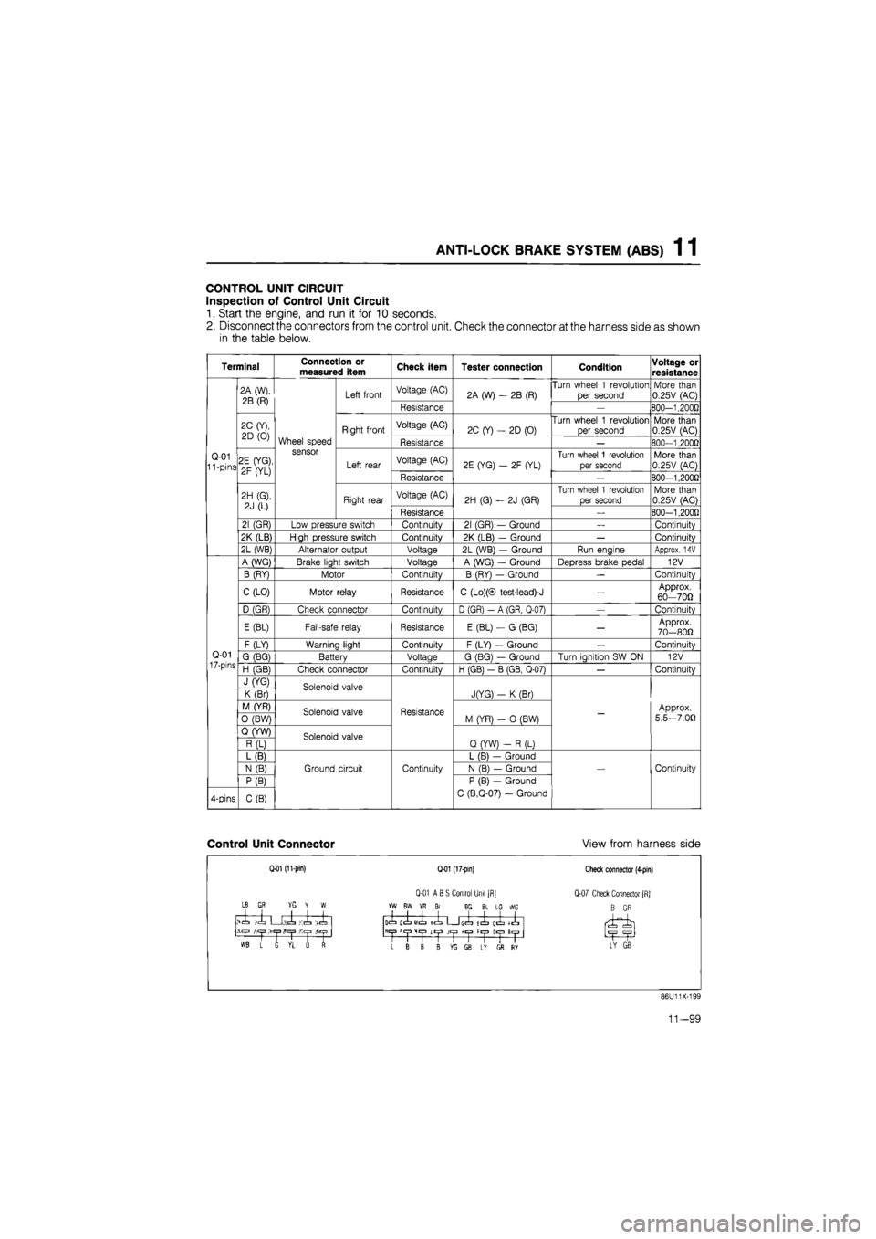
CONTROL UNIT CIRCUIT
Inspection of Control Unit Circuit
1. Start the engine, and run it for 10 seconds.
2. Disconnect the connectors from the control unit. Check the connector at the harness side as shown
in the table below.
Terminal Connection or measured item Check item Tester connection Condition Voltage or
resistance
Q-01 11 -pins
2A (W),
2B (R)
Wheel speed sensor
Left front Voltage (AC) 2A (W)
- 2B
(R) Turn wheel
1
revolution
per second More than 0.25V (AC)
Q-01 11 -pins
2A (W),
2B (R)
Wheel speed sensor
Left front
Resistance
2A (W)
- 2B
(R)
—
800-1.2000
Q-01 11 -pins
2C (Y),
2D
(0)
Wheel speed sensor
Right front Voltage (AC) 2C (Y)
-
2D (0) Turn wheel
1
revolution
per second More than 0.25V (AC)
Q-01 11 -pins
2C (Y),
2D
(0)
Wheel speed sensor
Right front
Resistance
2C (Y)
-
2D (0)
—
800-1,2000
Q-01 11 -pins 2E (YG),
2F (YL)
Wheel speed sensor
Left rear Voltage (AC) 2E (YG)
- 2F
(YL) Turn wheel
1
revolution
per second More than 0.25V (AC) Q-01 11 -pins 2E (YG),
2F (YL)
Wheel speed sensor
Left rear
Resistance
2E (YG)
- 2F
(YL)
—
800-1,200G
Q-01 11 -pins
2H (G).
2J
(L)
Wheel speed sensor
Right rear Voltage (AC) 2H (G)
- 2J
(GR)
Turn wheel
1
revolution
per second More than 0.25V (AC)
Q-01 11 -pins
2H (G).
2J
(L)
Wheel speed sensor
Right rear
Resistance
2H (G)
- 2J
(GR)
_
800-1,200fl
Q-01 11 -pins
21 (GR) Low pressure switch Continuity 21 (GR)
-
Ground
—
Continuity
Q-01 11 -pins
2K (LB) High pressure switch Continuity 2K (LB)
-
Ground
—
Continuity
Q-01 11 -pins
2L (WB) Alternator output Voltage 2L (WB)
-
Ground Run engine Approx.
14V
Q-01
17-pins
A (WG) Brake light switch Voltage A (WG)
-
Ground Depress brake pedal 12V
Q-01
17-pins
B (RY) Motor Continuity B (RY)
—
Ground
—
Continuity
Q-01
17-pins
C (LO) Motor relay Resistance C (Lo)(© test-lead)-J
—
Approx. 60—700
Q-01
17-pins
D (GR) Check connector Continuity D (GR)
- A
(GR, Q-07)
—
Continuity
Q-01
17-pins
E (BL) Fail-safe relay Resistance E (BL)
- G
(BG)
—
Approx. 70-800
Q-01
17-pins
F (LY) Warning light Continuity F (LY)
-
Ground
—
Continuitv Q-01
17-pins G (BG) Battery Voltage G (BG)
—
Ground Turn ianition
SW ON
12V Q-01
17-pins H (GB) Check connector Continuitv H (GB)
- B
(GB. Q-07)
—
Continuitv
Q-01
17-pins
J (YG) Solenoid valve
Resistance
JfYG)
- K
(Br)
-
Approx.
5.5—7.00
Q-01
17-pins
K (Br) Solenoid valve
Resistance
JfYG)
- K
(Br)
-
Approx.
5.5—7.00
Q-01
17-pins
M (YR) Solenoid valve Resistance M (YR)
- 0
(BW)
-
Approx.
5.5—7.00
Q-01
17-pins
0 (BW) Solenoid valve Resistance M (YR)
- 0
(BW)
-
Approx.
5.5—7.00
Q-01
17-pins
Q (YW) Solenoid valve
Resistance
Q (YW)
- R
(L)
-
Approx.
5.5—7.00
Q-01
17-pins
R (L) Solenoid valve
Resistance
Q (YW)
- R
(L)
-
Approx.
5.5—7.00
Q-01
17-pins
L (B)
Ground circuit Continuity
L (B)
—
Ground
Continuity
Q-01
17-pins
N
(B)
Ground circuit Continuity N (B)
—
Ground Continuity
Q-01
17-pins
P (B)
Ground circuit Continuity
P (B)
—
Ground
C (B.Q-07)
-
Ground
Continuity
4-pins C(B)
Ground circuit Continuity
P (B)
—
Ground
C (B.Q-07)
-
Ground
Continuity
Control Unit Connector View from harness side
Q-01 (11-pin)
LB
GR YG Y W
>1 ,1 U;.l Ki -X
1 L G VL rf
Q-01 (17-pin)
Q-01 ABS Control Unit [R]
YW BW YR Br 8G BL LO WG
icL olL
MIL
ICL G(=L tl ij^" llyl
>1
CjJ
Lt|J JCjJ fiC|3 H«|3
L B B B ffi SB L* GS RY
Check connector (4-pin)
Q-07 Check Connector [RJ
B GR
LY GB
86U11X-199
11—99
Page 1551 of 1865
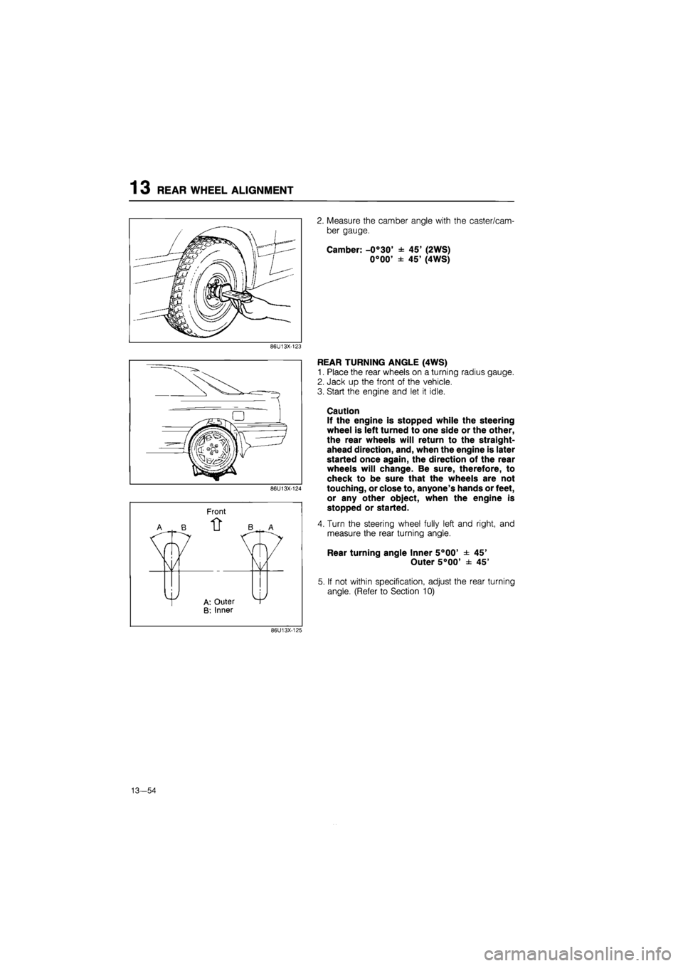
13 REAR WHEEL ALIGNMENT
2. Measure the camber angle with the caster/cam-
ber gauge.
Camber: -0°30' ± 45' (2WS)
0°00' ± 45' (4WS)
86U13X-123
Front
EAR TURNING ANGLE (4WS)
Place the rear wheels on a turning radius gauge.
Jack up the front of the vehicle.
Start the engine and let it idle.
Caution
If the engine is stopped while the steering
wheel is left turned to one side or the other,
the rear wheels will return to the straight-
ahead direction, and, when the engine is later
started once again, the direction of the rear
wheels will change. Be sure, therefore, to
check to be sure that the wheels are not
touching, or close to, anyone's hands or feet,
or any other object, when the engine is
stopped or started.
Turn the steering wheel fully left and right, and
measure the rear turning angle.
Rear turning angle Inner 5°00' ± 45'
Outer 5°00' ± 45'
If not within specification, adjust the rear turning
angle. (Refer to Section 10)
86U13X-125
13—54
Page 1681 of 1865
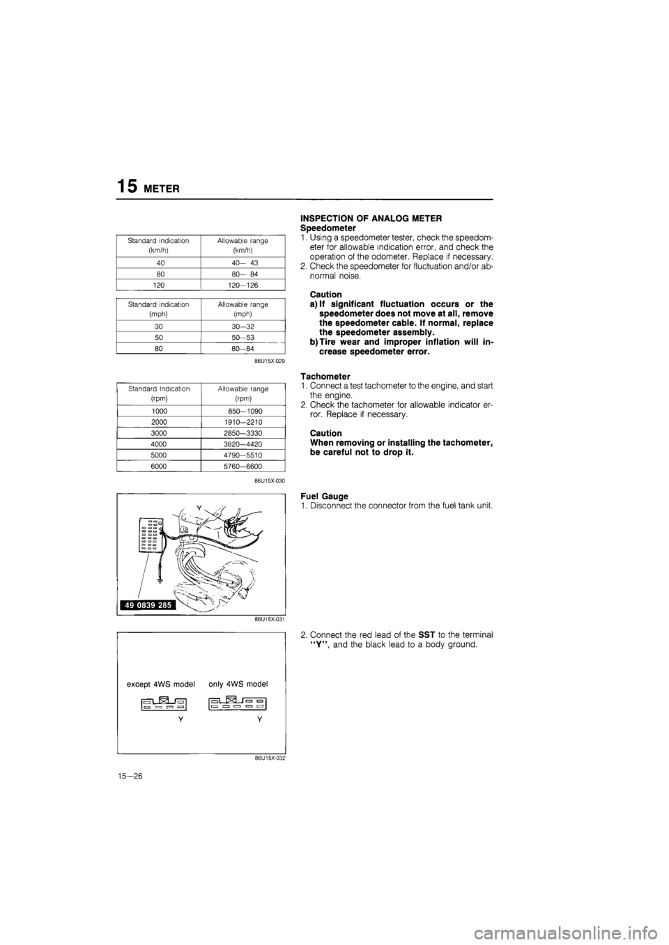
15 METER
Standard indication
(km/h)
Allowable range
(km/h)
40 40-
43
80 80-
84
120
120—126
Standard indication
(mph)
Allowable range
(mph)
30
30-32
50
50-53
80
80—84
86U15X-029
Standard Indication
(rpm)
Allowable range
(rpm)
1000
850—1090
2000 1910-2210
3000 2850-3330
4000 3820-4420
5000 4790—5510
6000 5760-6600
86U15X-030
INSPECTION OF ANALOG METER
Speedometer
1. Using a speedometer tester, check the speedom-
eter for allowable indication error, and check the
operation of the odometer. Replace if necessary.
2. Check the speedometer for fluctuation and/or ab-
normal noise.
Caution
a) If significant fluctuation occurs or the
speedometer does not move at all, remove
the speedometer cable. If normal, replace
the speedometer assembly.
b)Tire wear and improper inflation will in-
crease speedometer error.
Tachometer
1. Connect a test tachometer to the engine, and start
the engine.
2. Check the tachometer for allowable indicator er-
ror. Replace if necessary.
Caution
When removing or installing the tachometer,
be careful not to drop it.
Fuel Gauge
1. Disconnect the connector from the fuel tank unit.
86U15X-031
Connect the red lead of the SST to the terminal
"Y", and the black lead to a body ground.
86U15X-032
15-26
Page 1683 of 1865
15 METER
Standard Indication
(rpm)
Allowable range
(rpm)
1000
900—
950
2000 1900-1950
3000 2900—2950
4000 3900-3950
5000 4900—4950
6000 5900-5950
86U15X-037
86U15X-038
86U15X-039
Standard display Expanded display
E ©FUEL F E © FUEL F
"io — •
QJ1QOOODDOOOD
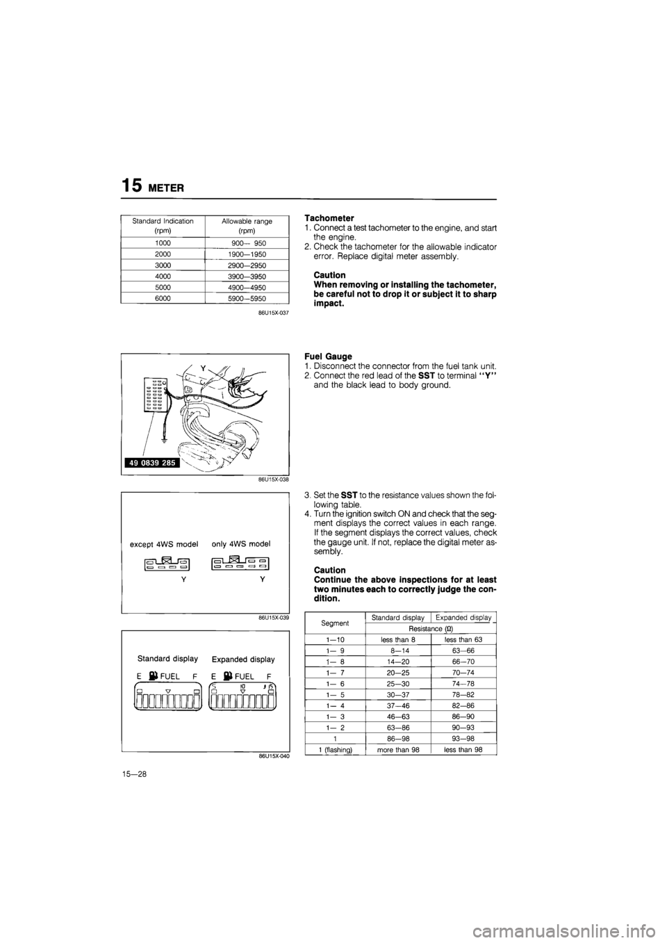
Tachometer
1. Connect a test tachometer to the engine, and start
the engine.
2. Check the tachometer for the allowable indicator
error. Replace digital meter assembly.
Caution
When removing or installing the tachometer,
be careful not to drop it or subject it to sharp
impact.
Fuel Gauge
1. Disconnect the connector from the fuel tank unit.
2. Connect the red lead of the SST to terminal "Y"
and the black lead to body ground.
86U15X-040
Set the SST to the resistance values shown the fol-
lowing table.
Turn the ignition switch ON and check that the seg-
ment displays the correct values in each range.
If the segment displays the correct values, check
the gauge unit. If not, replace the digital meter as-
sembly.
Caution
Continue the above inspections for at least
two minutes each to correctly judge the con-
dition.
Segment Standard display Expanded display Segment Resistance
(Q)
1-10
less than
8
less than
63
1-
9
8-14
63-66
1-
8
14—20 66-70
1-
7
20-25 70-74
1-
6
25-30 74-78
1-
5
30—37 78-82
1-
4
37-46 82-86
1—
3
46-63 86-90
1-
2
63-86 90-93
1
86-98 93-98
1
(flashing) more than
98
less than
98
15-28
Page 1695 of 1865
15 WARNING AND SENDER
86U15X-068
86U15X069
86U15X-070
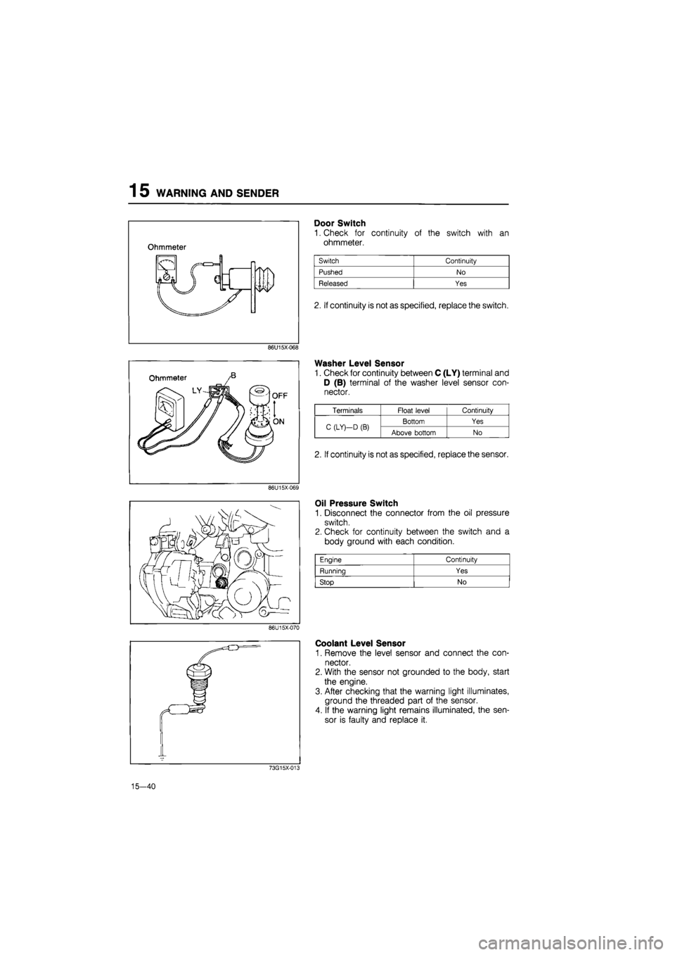
Door Switch
1. Check for continuity of the switch with an
ohmmeter.
2. If continuity is not as specified, replace the switch.
Washer Level Sensor
1. Check for continuity between C (LY) terminal and
D (B) terminal of the washer level sensor con-
nector.
Oil Pressure Switch
1. Disconnect the connector from the oil pressure
switch.
2. Check for continuity between the switch and a
body ground with each condition.
Coolant Level Sensor
1. Remove the level sensor and connect the con-
nector.
2. With the sensor not grounded to the body, start
the engine.
3. After checking that the warning light illuminates,
ground the threaded part of the sensor.
4. If the warning light remains illuminated, the sen-
sor is faulty and replace it.
73G15X-013
15—40
Engine Continuity
Running Yes
Stop No
Terminals Float level Continuity
C (LY)—D
(B)
Bottom Yes C (LY)—D
(B)
Above bottom No
2. If continuity is not as specified, replace the sensor.