Page 759 of 1865
STARTER (GASOLINE ENGINE, 1.4 KW TYPE) 5
86U05X-037
Internal gear
Drive pinion Gear shaft
Snap ring
Stopper
7BU05X-045
Snap ring
Stopper
Overrunning
\= clutch
7BU05X-046
ASSEMBLY
Assemble in the reverse order of disassembly, refer-
ring to the assembly note.
Assembly Note
Lubricate
During assembly lubricate the following points:
1. Gear of armature shaft
2. Internal gear and planetary gears
3. Plunger circumference
4. Lever
5. Ball
6. Gear shaft spline
7. Front bracket housing
Installation of Overrunning Clutch
1. Install the washer, internal gear, drive pinion stop-
per, and the snap ring on the gear shaft.
2. Press the stopper and the snap ring into position
as shown in the figure.
Installation of lever
Check the lever faces in the correct direction.
7BU05X-047
5—53
Page 770 of 1865

5 STARTER (DIESEL ENGINE, 2.0 KW TYPE)
Suitable _
steel plate
Armature
4BG05X-104
4BG05X-092
4BG05X-093
Bearing
Check for abnormal noise, looseness, insufficient
lubrication, etc. Replace the bearing if there is any
abnormality.
Take out the bearing, as shown in the figure, by us-
ing the suitable tools.
PERFORMANCE INSPECTION
Magnetic Switch
Disconnect the terminal M wire, and make the fol-
lowing tests.
Pull-in Test
The switch is normal
if
the pinion ejects outward when
the battery is connected as shown in the figure.
Caution
Do not supply power continuously for more
than 10 seconds.
Hold-in Test
1. After completing the pull-in test, disconnect the wire
from terminal M (with the pinion left ejected).
2. The hold-in coil is functioning properly if the pin-
ion does not return.
Return Test
1. Connect the battery between terminal M of the
magnetic switch and the body, as shown in the
figure.
2. Pull the pinion out manually to the pinion stopper
position.
3. The pinion should immediately return to its origi-
nal position when it is released.
4BG05X-094
5—64
Page 777 of 1865

STARTER (DIESEL ENGINE, 2.2 KW TYPE) 5
4BG05X-113
4BG05X-080
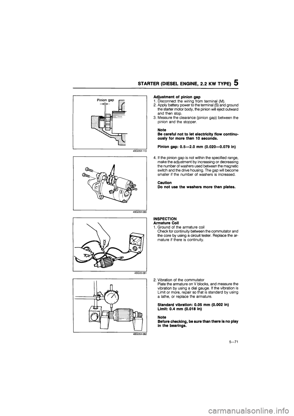
Adjustment of pinion gap
1. Disconnect the wiring from terminal (M).
2. Apply battery power to the terminal (S) and ground
the starter motor body, the pinion will eject outward
and then stop.
3. Measure the clearance (pinion gap) between the
pinion and the stopper.
Note
Be careful not to let electricity flow continu-
ously for more than 10 seconds.
Pinion gap: 0.5—2.0 mm (0.020—0.079 in)
4. If the pinion gap is not within the specified range,
make the adjustment by increasing or decreasing
the number of washers used between the magnetic
switch and the drive housing. The gap will become
smaller if the number of washers is increased.
Caution
Do not use the washers more than plates.
INSPECTION
Armature Coil
1. Ground of the armature coil
Check for continuity between the commutator and
the core by using a circuit tester. Replace the ar-
mature if there is continuity.
4BG05-081
2. Vibration of the commutator
Plate the armature on V blocks, and measure the
vibration by using a dial gauge. If the vibration is
Limit or more, repair so that is standard by using
a lathe, or replace the armature.
Standard vibration: 0.05 mm (0.002 in)
Limit: 0.4 mm (0.018 in)
Note
Before checking, be sure than there is no play
in the bearings.
4BG05X-Q82
5-71
Page 781 of 1865

5 STARTER (DIESEL ENGINE, 2.0 KW TYPE)
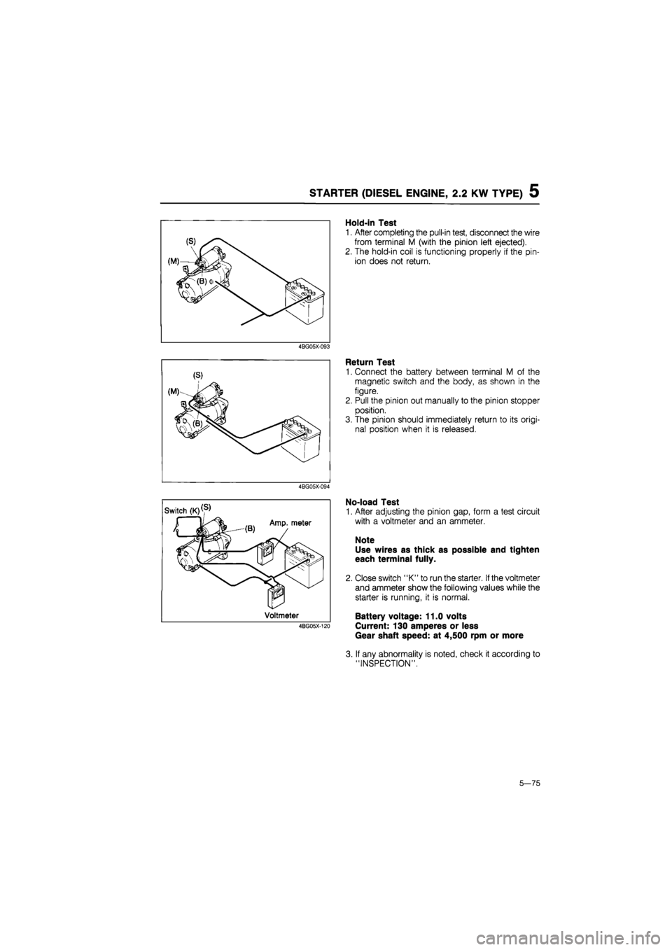
Hold-in Test
1. After completing the pull-in test, disconnect the wire
from terminal M (with the pinion left ejected).
2. The hold-in coil is functioning properly if the pin-
ion does not return.
4BG05X-093
Return Test
1. Connect the battery between terminal M of the
magnetic switch and the body, as shown in the
figure.
2. Pull the pinion out manually to the pinion stopper
position.
3. The pinion should immediately return to its origi-
nal position when it is released.
4BG05X-094
No-load Test
1. After adjusting the pinion gap, form a test circuit
with a voltmeter and an ammeter.
Note
Use wires as thick as possible and tighten
each terminal fully.
2. Close switch "K" to run the starter.
If
the voltmeter
and ammeter show the following values while the
starter is running, it is normal.
Battery voltage: 11.0 volts
Current: 130 amperes or less
Gear shaft speed: at 4,500 rpm or more
3. If any abnormality is noted, check it according to
"INSPECTION".
5—75
Page 896 of 1865

7B TROUBLESHOOTING (G4A-EL)
STEP 5 (TIME LAG TEST)
If the selector lever is shifted while the engine is idling, there will be a certain time lapse, or time lag,
before shock is felt. This step checks this time lag for checking condition of the 1-2, N-R, and N-D
accumulators, forward, and one-way clutches, 2-4 brake band, and low and reverse brake.
Preparation
76G07B-030
Procedure
1. Start the engine and check the idle speed in P range.
Idle speed: 900 ±58 rpm
2. Shift from N range to D range
3. Measure the time it takes from shifting until shock is felt, with a stop watch.
4. Shift the selector to N range and run the engine at idle speed for at least one minute.
5. Perform the test for the following shifts in the same manner.
(1) N D range (Hold mode)
(2) N -» R range
Note
Make three measurements for each test and take the average value.
Specified time lag: N -> D range
N -»• R range
Evaluation
Condition Possible Cause
N D (Economy) shifting
More than specification
Insufficient line pressure Forward clutch slipping One-way clutch 1 slipping One-way clutch 2 slipping N D (Economy) shifting
Less than specification N-D accumulator not operating properly
Excessive line pressure
N-D (Hold) shifting
More than specification
Insufficient line pressure Forward clutch slipping 2-4 brake band slipping One-way clutch 1 slipping N-D (Hold) shifting
Less than specification 1-2 accumulator not operating properly
Excessive line pressure
N R shifting
More than specification
Insufficient line pressure Low and reverse brake slipping Revese clutch slipping N R shifting
Less than specification N-R accumulator not operating properly
Excessive line pressure
86U07B-038
0.5—1.0 second
0.5—1.0 second
7B-30
Page 918 of 1865

7B TROUBLESHOOTING (G4A-HL)
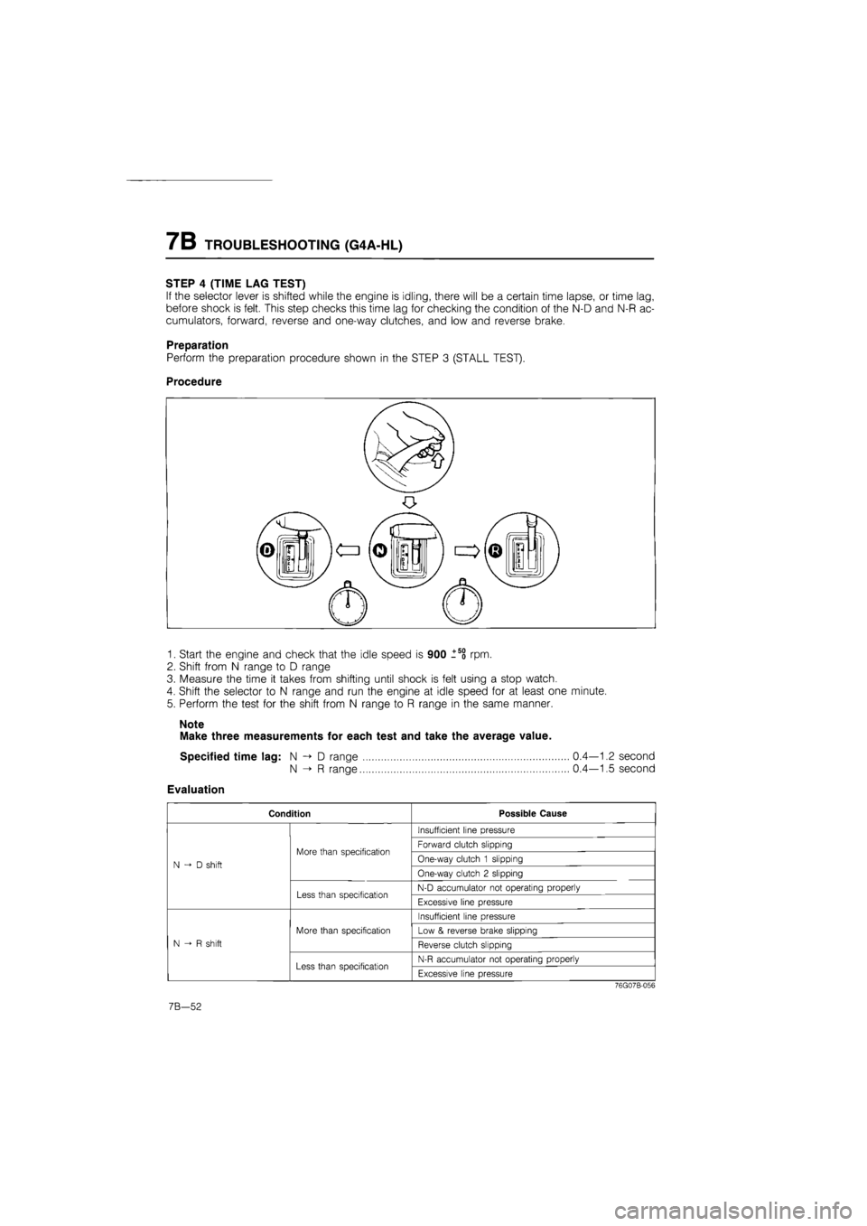
STEP 4 (TIME LAG TEST)
If the selector lever is shifted while the engine is idling, there will be a certain time lapse, or time lag,
before shock is felt. This step checks this time lag for checking the condition of the N-D and N-R ac-
cumulators, forward, reverse and one-way clutches, and low and reverse brake.
Preparation
Perform the preparation procedure shown in the STEP 3 (STALL TEST).
Procedure
1. Start the engine and check that the idle speed is 900 l5o rpm.
2. Shift from N range to D range
3. Measure the time it takes from shifting until shock is felt using a stop watch.
4. Shift the selector to N range and run the engine at idle speed for at least one minute.
5. Perform the test for the shift from N range to R range in the same manner.
Note
Make three measurements for each test and take the average value.
Specified time lag: N -> D range 0.4—1.2 second
N -> R range 0.4—1.5 second
Evaluation
Condition Possible Cause
N D shift
More than specification
Insufficient line pressure
N D shift
More than specification Forward clutch slipping
N D shift
More than specification One-way clutch 1 slipping N D shift
More than specification
One-way clutch 2 slipping N D shift
Less than specification N-D accumulator not operating properly
N D shift
Less than specification Excessive line pressure
N-R shift
More than specification
Insufficient line pressure
N-R shift
More than specification Low & reverse brake slipping
N-R shift
More than specification
Reverse clutch slipping N-R shift
Less than specification N-R accumulator not operating properly
N-R shift
Less than specification Excessive line pressure
76G07B-056
7B-52
Page 1131 of 1865

TROUBLESHOOTING 7C
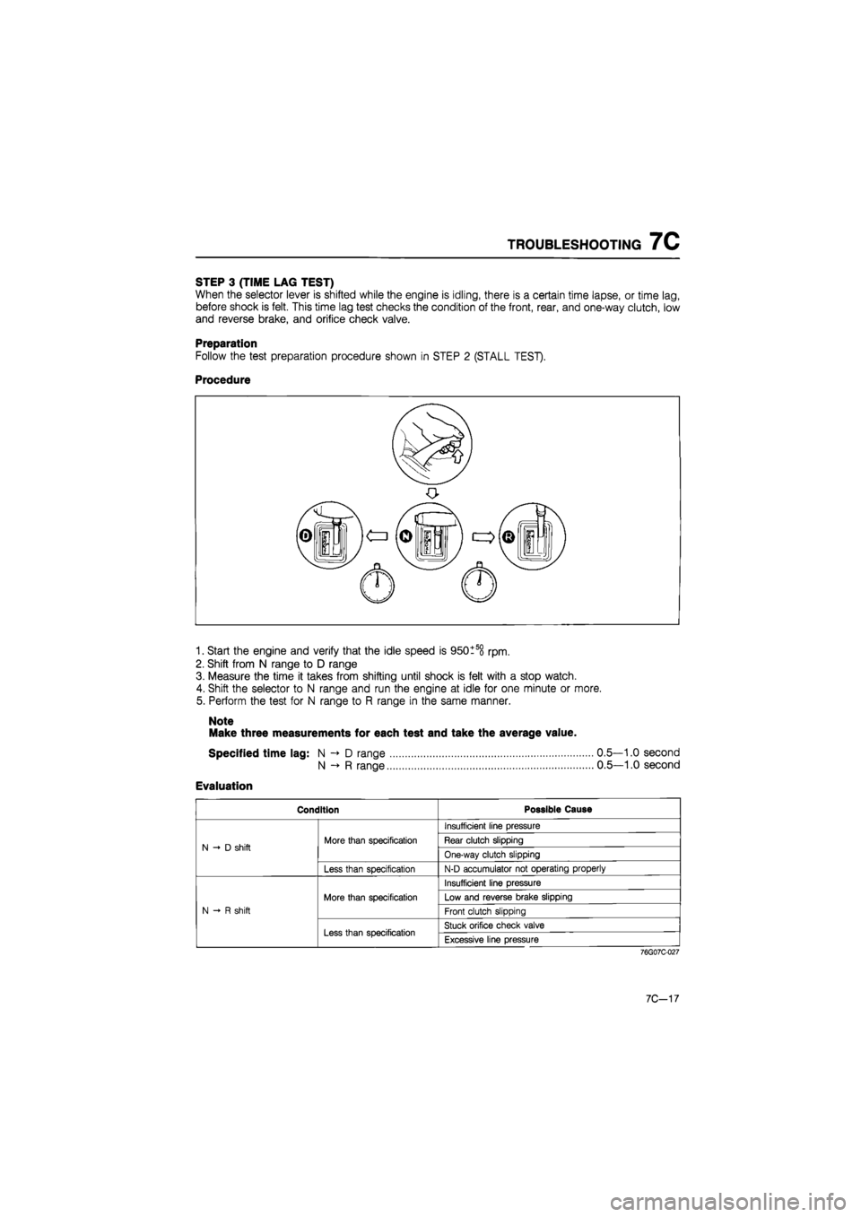
STEP 3 (TIME LAG TEST)
When the selector lever is shifted while the engine is idling, there is a certain time lapse, or time lag,
before shock is felt. This time lag test checks the condition of the front, rear, and one-way clutch, low
and reverse brake, and orifice check valve.
Preparation
Follow the test preparation procedure shown in STEP 2 (STALL TEST).
Procedure
1. Start the engine and verify that the idle speed is 950tso rpm.
2. Shift from N range to D range
3. Measure the time it takes from shifting until shock is felt with a stop watch.
4. Shift the selector to N range and run the engine at idle for one minute or more.
5. Perform the test for N range to R range in the same manner.
Note
Make three measurements for each test and take the average value.
Specified time lag: N D range 0.5—1.0 second
N R range 0.5—1.0 second
Evaluation
Condition Possible Cause
N -» D shift More than specification
Insufficient line pressure
N -» D shift More than specification Rear clutch slipping N -» D shift More than specification
One-way clutch slipping N -» D shift
Less than specification N-D accumulator not operating properly
N-R shift
More than specification
Insufficient line pressure
N-R shift
More than specification Low and reverse brake slipping
N-R shift
More than specification
Front clutch slipping N-R shift
Less than specification Stuck orifice check valve
N-R shift
Less than specification Excessive line pressure
76G07C-027
7C-17
Page 1320 of 1865
1 0 4-WHEEL STEERING GEAR AND LINKAGE
86U10X-301
86U10X-302
86U10X-303
4WS PERFORMANCE INSPECTION
1. Steering Angle Transfer Shaft Alignement
(Simple inspection)
(1) Put masking tape on the steering wheel and
column cover.
(2) Drive the vehicle on a straight, flat road for at
least 30 m (18.6 ft) and note the steering wheel
position. Stop and mark the straight-ahead po-
sition on the steering wheel and column cover
tape. Drive the vehicle again and check the
marks.
(3) With the marks between the steering wheel and
column cover aligned, check that the rear
wheels do not turn off center when the engine
is started.
(4) If the rear wheels move, adjust the steering an-
gle transfer shaft.
(Inspection by dial indicator)
(1) Mark between the steering wheel and column
cover as shown above.
(2) Attach a scale on the column cover as shown
in the illustration.
86U10X-304
10-32