1987 MAZDA 626 stop start
[x] Cancel search: stop startPage 1419 of 1865
POWER BRAKE UNIT 1 1
86U11X-038
0
o
X
\ V^ Third
Second
^ First
86U11X-039
O X
fiSy
V
86U11X-040
Pedal-depression Pre!tur!9au9e
force gauge
^Intake manifold
86U11X-041
POWER BRAKE UNIT
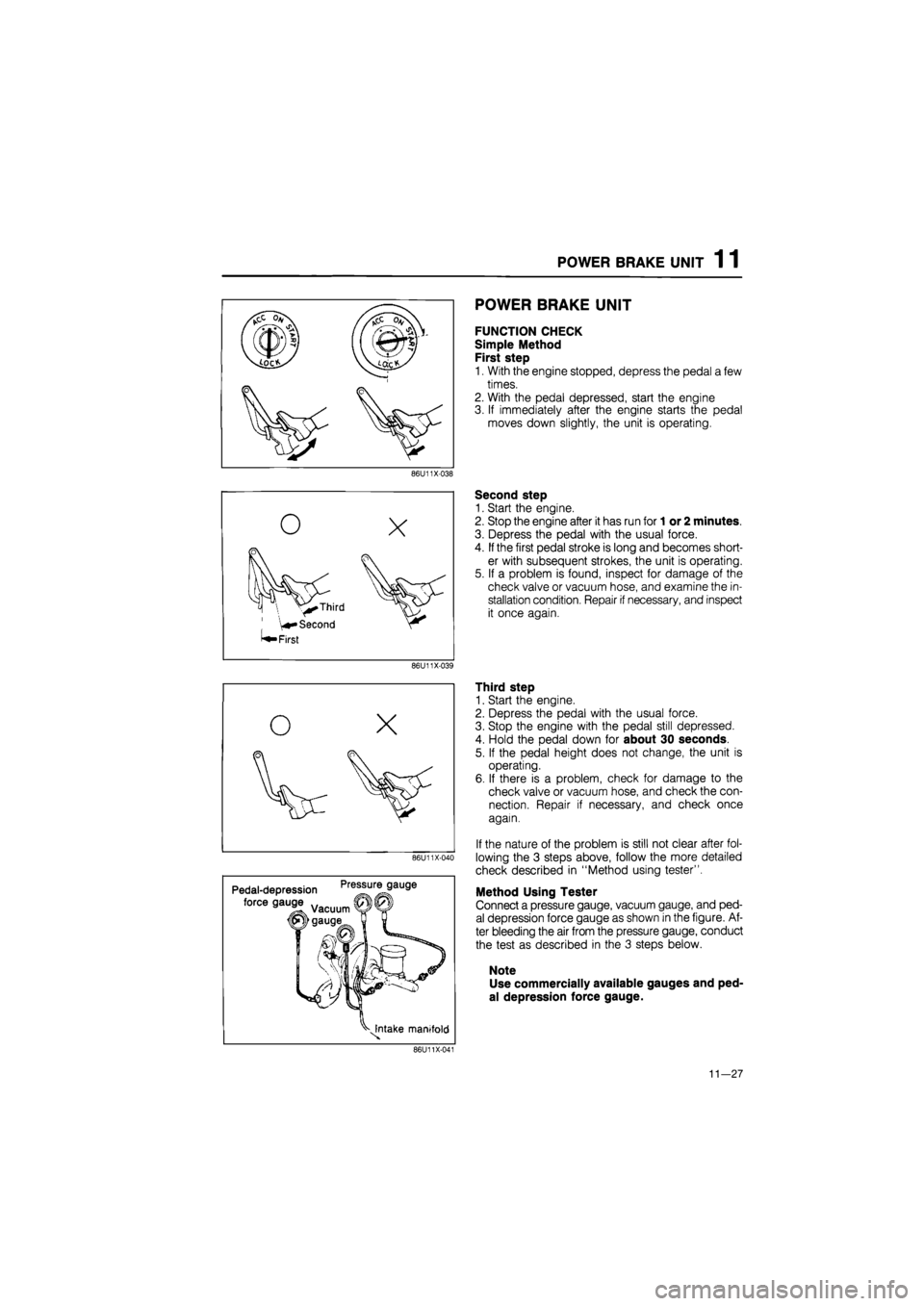
FUNCTION CHECK
Simple Method
First step
1. With the engine stopped, depress the pedal a few
times.
2. With the pedal depressed, start the engine
3. If immediately after the engine starts the pedal
moves down slightly, the unit is operating.
Second step
1. Start the engine.
2. Stop the engine after it has run for
1
or 2 minutes.
3. Depress the pedal with the usual force.
4.
If
the first pedal stroke is long and becomes short-
er with subsequent strokes, the unit is operating.
5. If a problem is found, inspect for damage of the
check valve or vacuum hose, and examine the in-
stallation condition. Repair if necessary, and inspect
it once again.
Third step
1. Start the engine.
2. Depress the pedal with the usual force.
3. Stop the engine with the pedal still depressed.
4. Hold the pedal down for about 30 seconds.
5. If the pedal height does not change, the unit is
operating.
6. If there is a problem, check for damage to the
check valve or vacuum hose, and check the con-
nection. Repair if necessary, and check once
again.
If the nature of the problem is still not clear after fol-
lowing the 3 steps above, follow the more detailed
check described in "Method using tester".
Method Using Tester
Connect a pressure gauge, vacuum gauge, and ped-
al depression force gauge as shown in the figure. Af-
ter bleeding the air from the pressure gauge, conduct
the test as described in the 3 steps below.
Note
Use commercially available gauges and ped-
al depression force gauge.
11—27
Page 1420 of 1865
1 1 POWER BRAKE UNIT
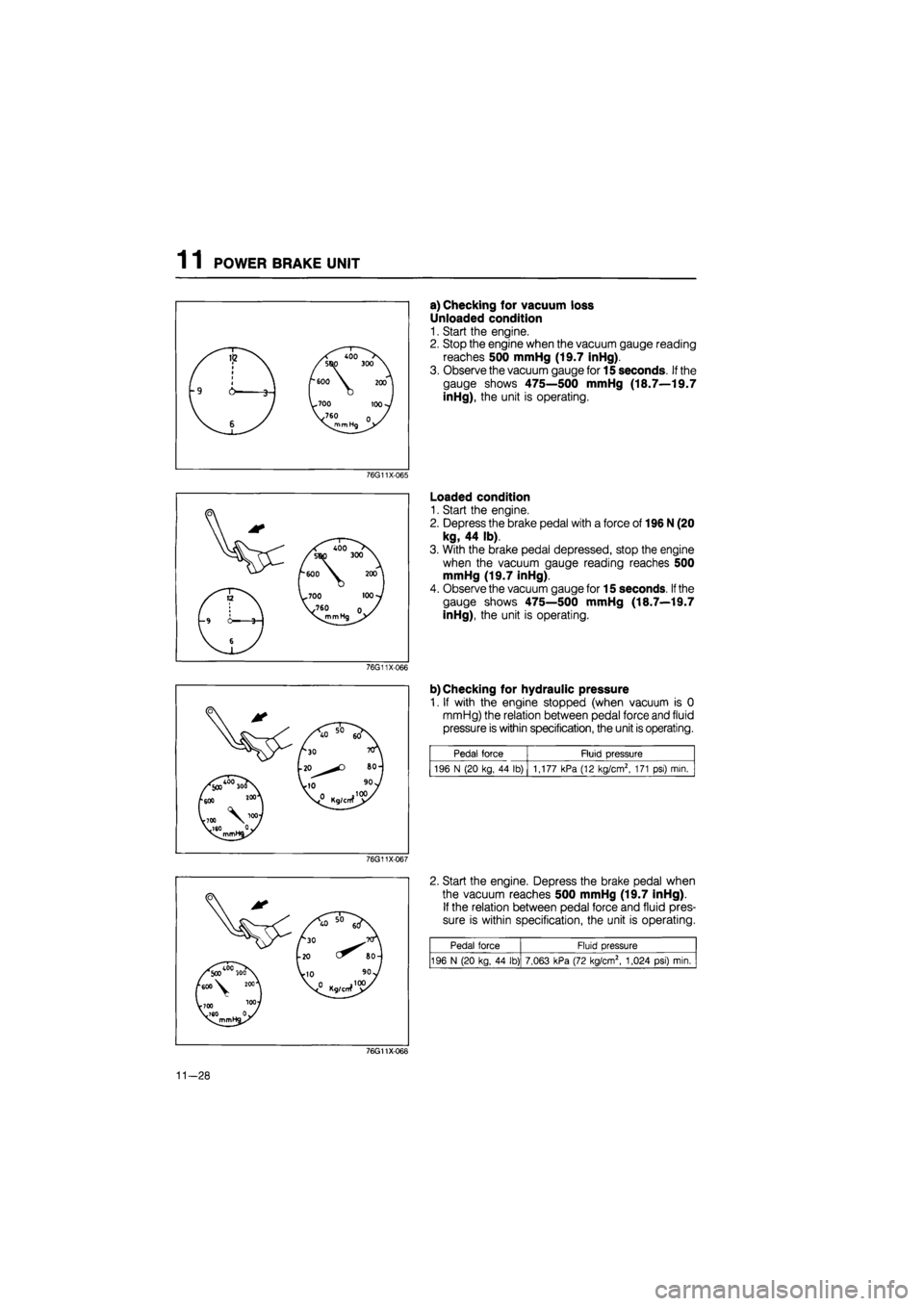
a) Checking for vacuum loss
Unloaded condition
1. Start the engine.
2. Stop the engine when the vacuum gauge reading
reaches 500 mmHg (19.7 inHg).
3. Observe the vacuum gauge for 15 seconds.
If
the
gauge shows 475—500 mmHg (18.7—19.7
inHg), the unit is operating.
76G11X-065
Loaded condition
1. Start the engine.
2. Depress the brake pedal with a force of 196 N (20
kg, 44 lb).
3. With the brake pedal depressed, stop the engine
when the vacuum gauge reading reaches 500
mmHg (19.7 inHg).
4. Observe the vacuum gauge for 15 seconds.
If
the
gauge shows 475—500 mmHg (18.7—19.7
inHg), the unit is operating.
76G11X066
b) Checking for hydraulic pressure
1. If with the engine stopped (when vacuum is 0
mmHg) the relation between pedal force and fluid
pressure is within specification, the unit is operating.
Pedal force Fluid pressure
196 N (20 kg, 44 lb) | 1,177 kPa (12 kg/cm2, 171 psi) mia
76G11X-067
2. Start the engine. Depress the brake pedal when
the vacuum reaches 500 mmHg (19.7 inHg).
If the relation between pedal force and fluid pres-
sure is within specification, the unit is operating.
Pedal force Fluid pressure
196 N (20 kg, 44 lb) 7,063 kPa (72 kg/cm2, 1,024 psi) min.
76G11X068
11-28
Page 1457 of 1865
PARKING BRAKE 1 1
86U11X-130
86U11X-131
PARKING BRAKE
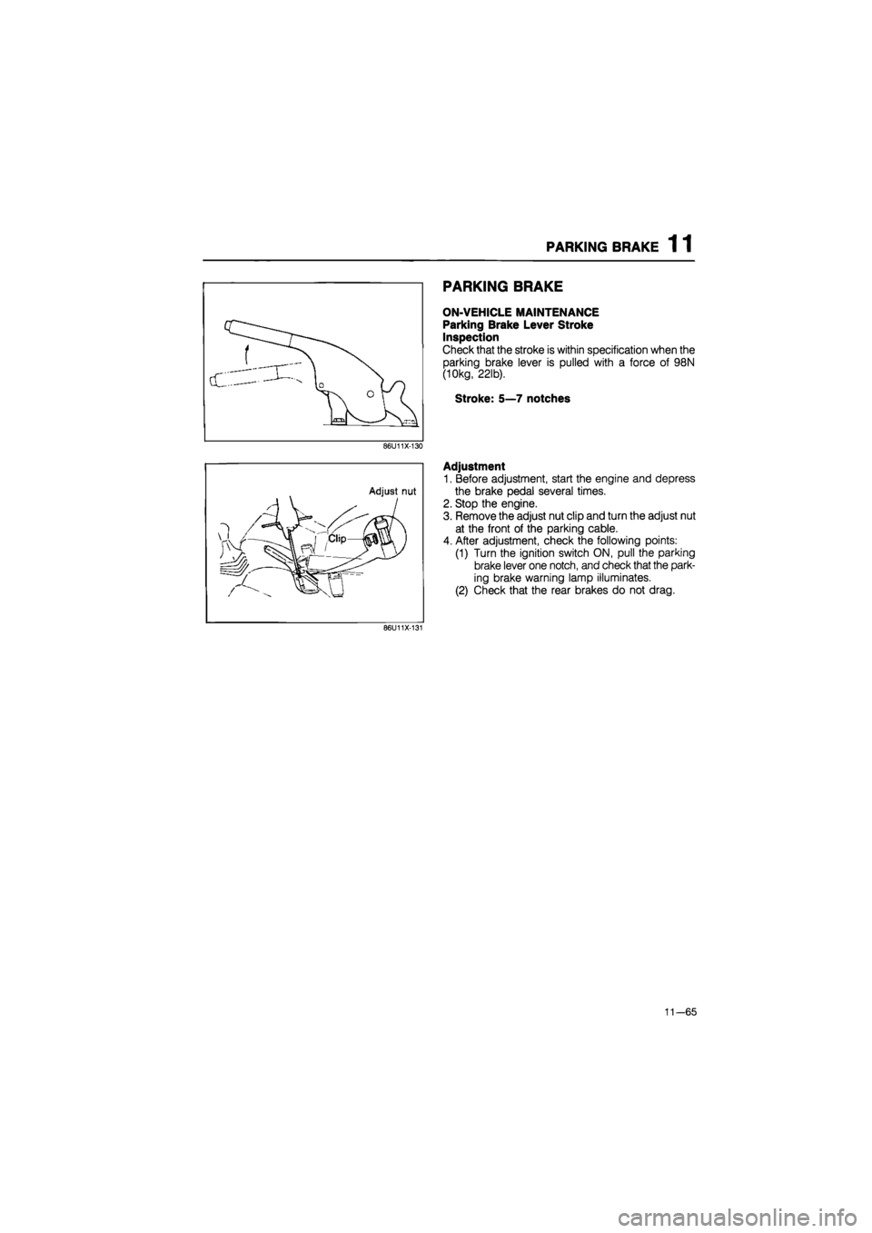
ON-VEHICLE MAINTENANCE
Parking Brake Lever Stroke
Inspection
Check that the stroke is within specification when the
parking brake lever is pulled with a force of 98N
(10kg, 22lb).
Stroke: 5—7 notches
Adjustment
1. Before adjustment, start the engine and depress
the brake pedal several times.
2. Stop the engine.
3. Remove the adjust nut clip and turn the adjust nut
at the front of the parking cable.
4. After adjustment, check the following points:
(1) Turn the ignition switch ON, pull the parking
brake lever one notch, and check that the park-
ing brake warning lamp illuminates.
(2) Check that the rear brakes do not drag.
11—65
Page 1551 of 1865
13 REAR WHEEL ALIGNMENT
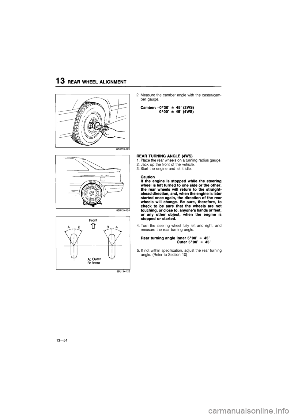
2. Measure the camber angle with the caster/cam-
ber gauge.
Camber: -0°30' ± 45' (2WS)
0°00' ± 45' (4WS)
86U13X-123
Front
EAR TURNING ANGLE (4WS)
Place the rear wheels on a turning radius gauge.
Jack up the front of the vehicle.
Start the engine and let it idle.
Caution
If the engine is stopped while the steering
wheel is left turned to one side or the other,
the rear wheels will return to the straight-
ahead direction, and, when the engine is later
started once again, the direction of the rear
wheels will change. Be sure, therefore, to
check to be sure that the wheels are not
touching, or close to, anyone's hands or feet,
or any other object, when the engine is
stopped or started.
Turn the steering wheel fully left and right, and
measure the rear turning angle.
Rear turning angle Inner 5°00' ± 45'
Outer 5°00' ± 45'
If not within specification, adjust the rear turning
angle. (Refer to Section 10)
86U13X-125
13—54
Page 1695 of 1865
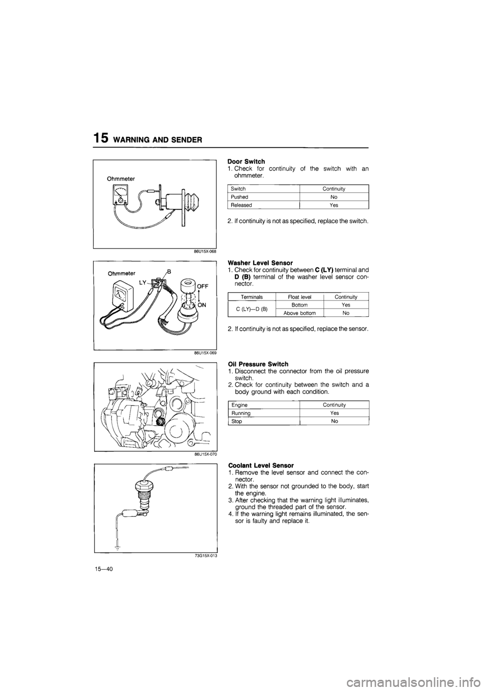
15 WARNING AND SENDER
86U15X-068
86U15X069
86U15X-070
Door Switch
1. Check for continuity of the switch with an
ohmmeter.
2. If continuity is not as specified, replace the switch.
Washer Level Sensor
1. Check for continuity between C (LY) terminal and
D (B) terminal of the washer level sensor con-
nector.
Oil Pressure Switch
1. Disconnect the connector from the oil pressure
switch.
2. Check for continuity between the switch and a
body ground with each condition.
Coolant Level Sensor
1. Remove the level sensor and connect the con-
nector.
2. With the sensor not grounded to the body, start
the engine.
3. After checking that the warning light illuminates,
ground the threaded part of the sensor.
4. If the warning light remains illuminated, the sen-
sor is faulty and replace it.
73G15X-013
15—40
Engine Continuity
Running Yes
Stop No
Terminals Float level Continuity
C (LY)—D
(B)
Bottom Yes C (LY)—D
(B)
Above bottom No
2. If continuity is not as specified, replace the sensor.
Page 1730 of 1865
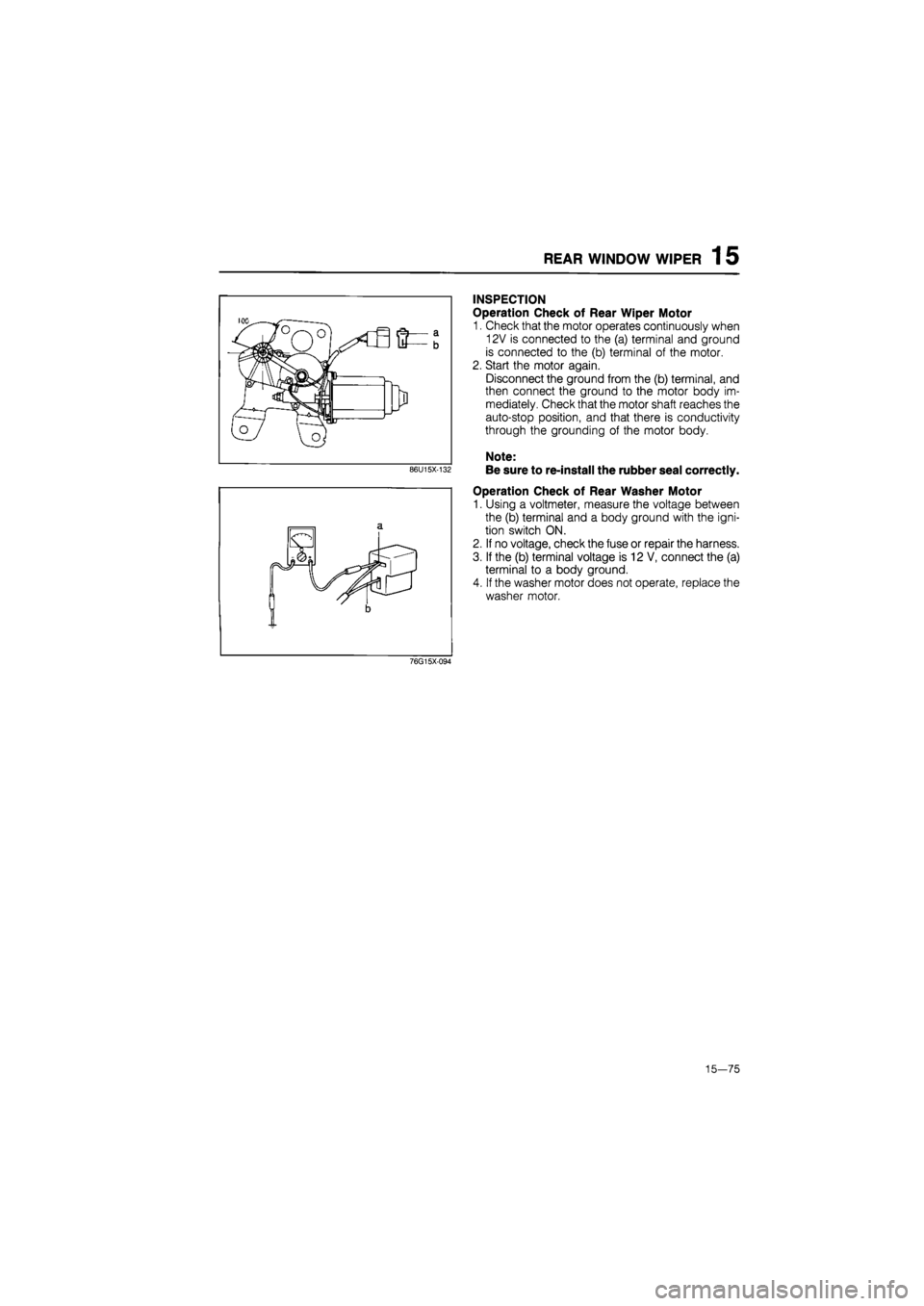
REAR WINDOW WIPER 1 5
86U15X-132
INSPECTION
Operation Check of Rear Wiper Motor
1. Check that the motor operates continuously when
12V is connected to the (a) terminal and ground
is connected to the (b) terminal of the motor.
2. Start the motor again.
Disconnect the ground from the (b) terminal, and
then connect the ground to the motor body im-
mediately. Check that the motor shaft reaches the
auto-stop position, and that there is conductivity
through the grounding of the motor body.
Note:
Be sure to re-install the rubber seal correctly.
Operation Check of Rear Washer Motor
1. Using a voltmeter, measure the voltage between
the (b) terminal and a body ground with the igni-
tion switch ON.
2. If no voltage, check the fuse or repair the harness.
3. If the (b) terminal voltage is 12 V, connect the (a)
terminal to a body ground.
4. If the washer motor does not operate, replace the
washer motor.
76G15X-094
15-75
Page 1832 of 1865
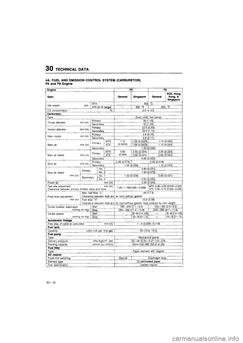
30 TECHNICAL DATA
4A. FUEL AND EMISSION CONTROL SYSTEM (CARBURETOR)
F6 and F8 Engine
Engine F6 F8
Spec. General Singapore General
ECE, Hong
Kong, &
Singapore
Idle speed rpm MTX 800
+ 50
0 Idle speed rpm ATX (in
N
range)
—
950 +58 900
+ 50
0
CO concentration °/o 2.0
± 0.5
Carburetor
Type Down draft two barrel
Throat diameter mm (in) Primary 30 (1.18) Throat diameter mm (in) Secondary 34 (1.34)
Venturi diameter mm (in) Primary 23.5 (0.93) Venturi diameter mm (in) Secondary 29.0 (1.14)
Main nozzle mm (in) Primary 2.6 (0.10) Main nozzle mm (in) Secondary 2.8 (0.11)
Primary MTX 1.10 1.09 (0.0429) 1.14 (0.045)
Main
jet
mm (in) Primary ATX (0.0433) 1.08 (0.0425) 1.12 (0.044)
Secondary 1.50 (0.059)
Primary MTX 0.60 0.60 (0.024) 0.55 (0.022)
Main
air
bleed mm (in) Primary ATX (0.024) 0.80 (0.031) 0.60 (0.024)
Secondary 0.50 (0.020)
Slow
jet
mm (in) Primary 0.48 (0.019) 0.46 (0.018) Slow
jet
mm (in) Secondary 1.00 (0.039) 1.10 (0.043)
Primary No.
1
0.80 (0.031)
Slow
air
bleed Primary No.
2
1.90 (0.075)
mm (in) Secondary No.
1
1.00 (0.039) 0.80 (0.031) Secondary No.
2
0.50 (0.020)
Power
jet
mm (in) 0.50 (0.020)
Fast idle adjustment
mm (in)
Clearance between primary throttle valve and bore 1.40-1.76(0.055-0.069) MTX: 0.48-0.64 (0.019-0 025) ATX: 0.56-0.72 (0.022-0.028)
Max. fuel flow
"L"
44 (17.3)
Float level adjustment Clearance between float and
air
horn without gasket
mm (in) Fuel stop
"H •
12.5 (0.49)
Clearance between float and
air
horn/without gasket; float lowered
by
own weight
Choke breaker diaphragm Start 180-240 (7.1-9.5) 100—160 (3.9-6.3)
mmHg
(in Hg)
Stop 290—350 (11.4-13.8) 220-280 (8.7-11.0)
Choke opener Start
—
35-65 (1.4-2.6)
—
35-65 (1.4-2.6)
mmHg
(in Hg)
Stop
—
130-190 (5.1-7.5)
—
130-190
(5,1-7.5)
Accelerator linkage
Free plav
of
cable
at
carburetor mm (in) 1-3 (0.039—0.118)
Fuel tank
Capacity Liters (US gal, Imp gal) 60 (15.9, 13.2)
Fuel pump
Type Mechanical pump
Delivery pressure kPa (kg/cm2,
psi)
20-26 (0.20-0.27, 2.8-3.8)
Feedina capacity cc/min (cu in/min) More than 860 (52.5)
at
idle
Fuel filter
Type Paper element with magnet
Air cleaner
Fresh-Hot switching Manual Diaphragm type
Element
tvDe
Oil permeated paper
Fuel specification Leaded regular
30-18
Page 1833 of 1865
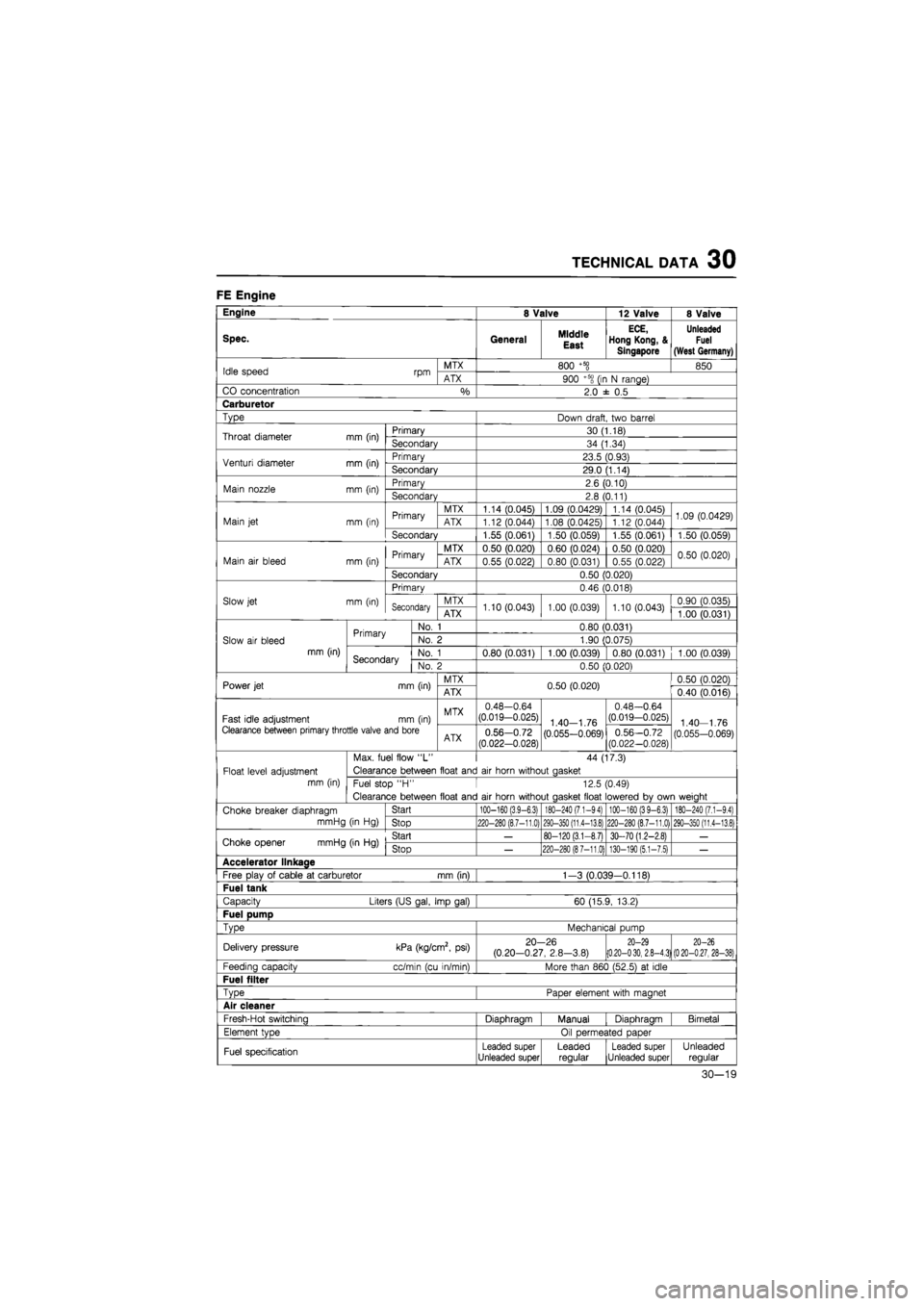
TECHNICAL DATA 30
FE Engine
Engine 8 Valve 12 Valve 8 Valve
Spec. General Middle
East
ECE,
Hong Kong, &
Singapore
Unleaded
Fuel
(West Germany)
Idle speed rpm MTX 800
+5§
850 Idle speed rpm ATX 900 +5S
(ir
N range)
CO concentration
%
2.0
± 0,5
Carburetor
Type Down draft, two barrel
Throat diameter mm (in) Primary 30 (1.18) Throat diameter mm (in) Secondary 34 (1.34)
Venturi diameter mm (in) Primary 23.5 (0.93) Venturi diameter mm (in) Secondary 29.0 (1.14)
Main nozzle mm (in) Primary 2.6 (0.10) Main nozzle mm (in) Secondary 2.8 (0.11)
Primary MTX 1.14 (0.045) 1.09 (0.0429) 1.14 (0.045) 1.09 (0.0429) Main
jet
mm (in) Primary ATX 1.12 (0.044) 1.08 (0.0425) 1.12 (0.044) 1.09 (0.0429)
Secondary 1.55 (0.061) 1.50 (0.059) 1.55 (0.061) 1.50 (0.059)
Primary MTX 0.50 (0.020) 0.60 (0.024) 0.50 (0.020) 0.50 (0.020) Main
air
bleed mm (in) Primary ATX 0.55 (0.022) 0.80 (0.031) 0.55 (0.022) 0.50 (0.020)
Secondary 0.50 (0.020)
Primary 0.46 (0.018)
Slow jet mm (in) Secondary MTX 1.10 (0.043) 1.00 (0.039) 1.10 (0.043) 0.90 (0.035) Secondary ATX 1.10 (0.043) 1.00 (0.039) 1.10 (0.043) 1.00 (0.031)
Primary No.
1
0.80 (0.031)
Slow
air
bleed Primary No.
2
1.90 (0.075)
mm (in) Secondary No.
1
0.80 (0.031) 1.00 (0.039) 0.80 (0.031) 1.00 (0.039) Secondary No.
2
0.50 (0.020)
Power jet mm (in) MTX 0.50 (0.020) 0.50 (0.020) Power jet mm (in) ATX 0.50 (0.020) 0.40 (0.016)
Fast idle adjustment mm (in) MTX 0.48-0.64 (0.019-0.025) 1 40—1
76
0.48-0.64 (0.019-0.025) 1
40
1
76
Clearance between primary throttle valve and bore ATX 0.56-0.72
(0.022-0.028) (0.055-0.069) 0.56-0.72 (0.022-0.028) (0.055-0.069)
Max. fuel flow
"L"
44 (17.3)
Float level adjustment Clearance between float and
air
horn without aasket
mm (in) Fuel stop
"H •
12.5 (0.49)
Clearance between float and
air
horn without aasket float lowered
bv
own weiaht
Choke breaker diaphragm Start
100-160 (3,9-6.3) 180-240 (7.1-94) 100-160 (39-6.3) 180-240 (7.1-9,4)
mmHg
(in Hg)
Stop
220-280 (8.7-11,0) 290-350 (11,4-13.8) 220-280 (8.7-11.0) 290-350 (11.4-13.8)
Choke opener mmHg (in
Hg)
Start
—
80-120 (3.1-8.7) 30-70 (1.2-2.8)
—
Choke opener mmHg (in
Hg)
Stop
—
220-280 (87-11.0) 130-190 (5.1-7.5)
—
Accelerator llnkaae
Free play
of
cable
at
carburetor mm (in) 1-3 (0.039-0.118)
Fuel tank
Capacity Liters (US gal, Imp gal) 60 (15.9, 13.2)
Fuel pump
TvDe
Mechanical pump
Delivery pressure kPa (kg/cm2,
psi)
20-26 (0.20-0.27, 2.8-3.8)
20-29 (0.20-030, 2.8-4.3) 20-26
(020-0.27, 28-38)
Feeding capacity cc/min (cu in/min) More than 860 (52.5)
at
idle
Fuel filter
TvDe
Paoer element with maanet
Air cleaner
Fresh-Hot switchina Diaohraam Manual Diaohraam Bimetal
Element tvoe Oil oermeated oaoer
Fuel specification Leaded super Unleaded super Leaded regular Leaded super Unleaded super Unleaded regular
30-19