1987 MAZDA 626 brake
[x] Cancel search: brakePage 1295 of 1865
TROUBLESHOOTING GUIDE 1 0
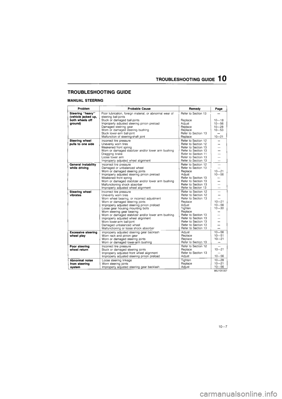
TROUBLESHOOTING GUIDE
MANUAL STEERING
Problem Probable Cause Remedy Page
Steering "heavy" Poor lubrication, foreign material, or abnormal wear of Refer to Section 13
(vehicle jacked up, steering bail-joints
both wheels off Stuck or damaged ball-joints Replace 10--18 ground) Improperly adjusted steering pinion preload Adjust 10--56
Damaged steering gear Replace 10--28 Worn or damaged steering bushing Replace 10--53 Stuck lower-arm ball-joint Refer to Section 13
Malfunction of steering-shaft joint Replace 10--21
Steering wheel Incorrect tire pressure Refer to Section 12
pulls to one side Unevenly worn tires Refer to Section 12
Weakened front spring Refer to Section 13 Worn or damaged stabilizer and/or lower arm bushing Refer to Section 13
Dragging brake Refer to Section 11
Loose lower arm Refer to Section 13
Improperly adjusted wheel alignment Refer to Section 13
General instability Incorrect tire pressure Refer to Section 12
while driving Damaged or unbalanced wheel Refer to Section 13
Worn or damaged steering joints Replace 10--21 Improperly adjusted steering pinion preload Adjust 10--56
Weakened front spring Refer to Section 13
Worn or damaged stabilizer and/or lower arm bushing Refer to Section 13
Malfunctioning shock absorber Refer to Section 13 Improperly adjusted wheel alignment Refer to Secton 13
Steering wheel Incorrect tire pressure Refer to Section 12
vibrates Unevenly worn tires Refer to Section 12
Worn wheel bearing, or incorrect adjustment Refer to Section 13
Worn or damaged steering joints Replace 10--21
Improperly adjusted steering pinion preload Adjust 10--56
Loose gear housing mounting bolts Tighten 10--30
Worn steering gear bearing Replace
Worn or damaged stabilizer and/or lower arm bushing Refer to Section 13
Improperly adjusted wheel alignment Refer to Section 13
Worn lower-arm ball-joint Refer to Section 13
Damaged unbalanced wheel Refer to Section 13
Malfunctionina or loose shock absorber Refer to Section 13
Excessive steering Improperly adjusted steering gear backlash Adjust 10--56
wheel play Worn rack and pinion gear Replace 10--51
Worn or damaged steering joints Replace 10--21
Worn or damaaed lower-arm bushinq Refer to Section 13
Poor steering Incorrect tire pressure Refer to Section 12
wheel return Stuck or damaged steering joints Replace 10 -21
Improperly adjusted front wheel alignment Refer to Section 13
Improperly adjusted steering pinion preload Adjust 10--56
Abnormal noise Loose steering linkage Tighten 10--28
from steering Worn steering joints Replace 10--21
system ImDroDerlv adiusted steerina aear backlash Adiust 10--56
86U10X-007
10—7
Page 1296 of 1865

1 0 TROUBLESHOOTING GUIDE
POWER STEERING
Problem Possible cause Remedy Page
Hard steering
Loose
or
damaged belt Low fluid level,
or air in
fluid Leakage
of
fluid
Malfunctioning electrical system* Insufficient oil pump pressure Improperly adjusted wheel alignment Malfunctioning steering gear Linkage ball joint not operating smoothly
Adjust
or
replace Add fluid
or
bleed
air
Repair
or
replace Repair
or
replace Repair
or
replace Refer
to
Section
13
Repair
or
replace Replace
10—12 10-11 10-13 10-87 10-16
10—28,
37
10-18
Poor return
Insufficient tire pressure
Improperly adjusted wheel alignment
Ball-joint not operating smoothly
Steering shaft contacting something
Refer
to
Section
12
Refer
to
Section
13
Replace
Repair
10-20 10-21
Excessive play
Loose gear box housing mounting bolts Worn linkage
or
tie-rod ball joint Worn lower ball joint Worn
or
damaged steering joint Worn rack and pinion gear
Tighten Replace
Refer
to
Section
13
Replace
Replace
10—30
10—18
10—21
10-58,
75
Steering wheel
vibrates
Insufficient tire pressure Damaged
or
unbalanced wheel Improperly adjusted wheel alignment Loose gear box housing mounting bolts Incorrect pinion preload adjustment Worn ball joints
Loose shock absorber mounting Malfunctioning shock absorber
Refer
to
Section
12
Refer
to
Section
13
Refer
to
Section
13
Tighten Adjust
Replace Refer
to
Section
13
Refer
to
Section
13
10-30 10-72,
81
10—18
Steering wheel
pulls
Unevenly worn tires
Incorrect tire pressure
Dragging brake
Improperly adjusted wheel alignment
Refer
to
Section
12
Refer
to
Section
12
Refer
to
Section
11
Refer
to
Section
13 —
Excessively light
steering at high
speed*
Malfunctioning electrical system Repair
or
replace 10-87
*... Only
for
electronically
-
controlled type
76G10X-002
10—8
Page 1329 of 1865
4-WHEEL STEERING GEAR AND LINKAGE 1 0
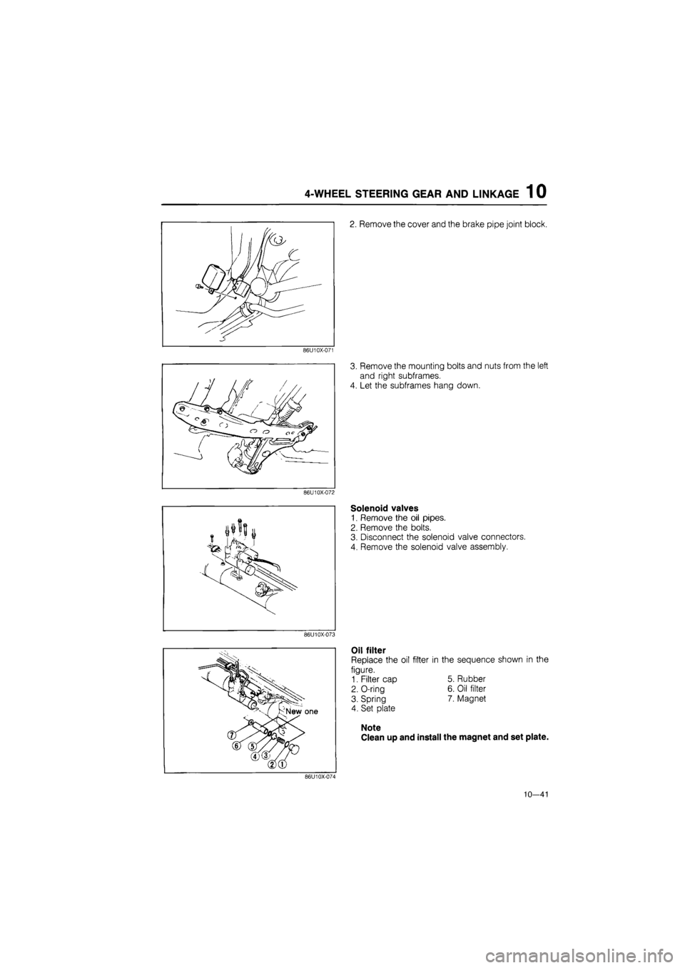
2. Remove the cover and the brake pipe joint block.
86U10X-071
3. Remove the mounting bolts and nuts from the left
and right subframes.
4. Let the subframes hang down.
86U10X-072
J i/W i
Y
Solenoid valves
1. Remove the oil pipes.
2. Remove the bolts.
3. Disconnect the solenoid valve connectors.
4. Remove the solenoid valve assembly.
86U10X-073
Oil filter
Replace the oil filter in the sequence shown in the
figure.
1. Filter cap 5. Rubber
2. O-ring 6. Oil filter
3. Spring 7. Magnet
4. Set plate
Note
Clean up and install the magnet and set plate.
86U10X-074
10—41
Page 1393 of 1865
11
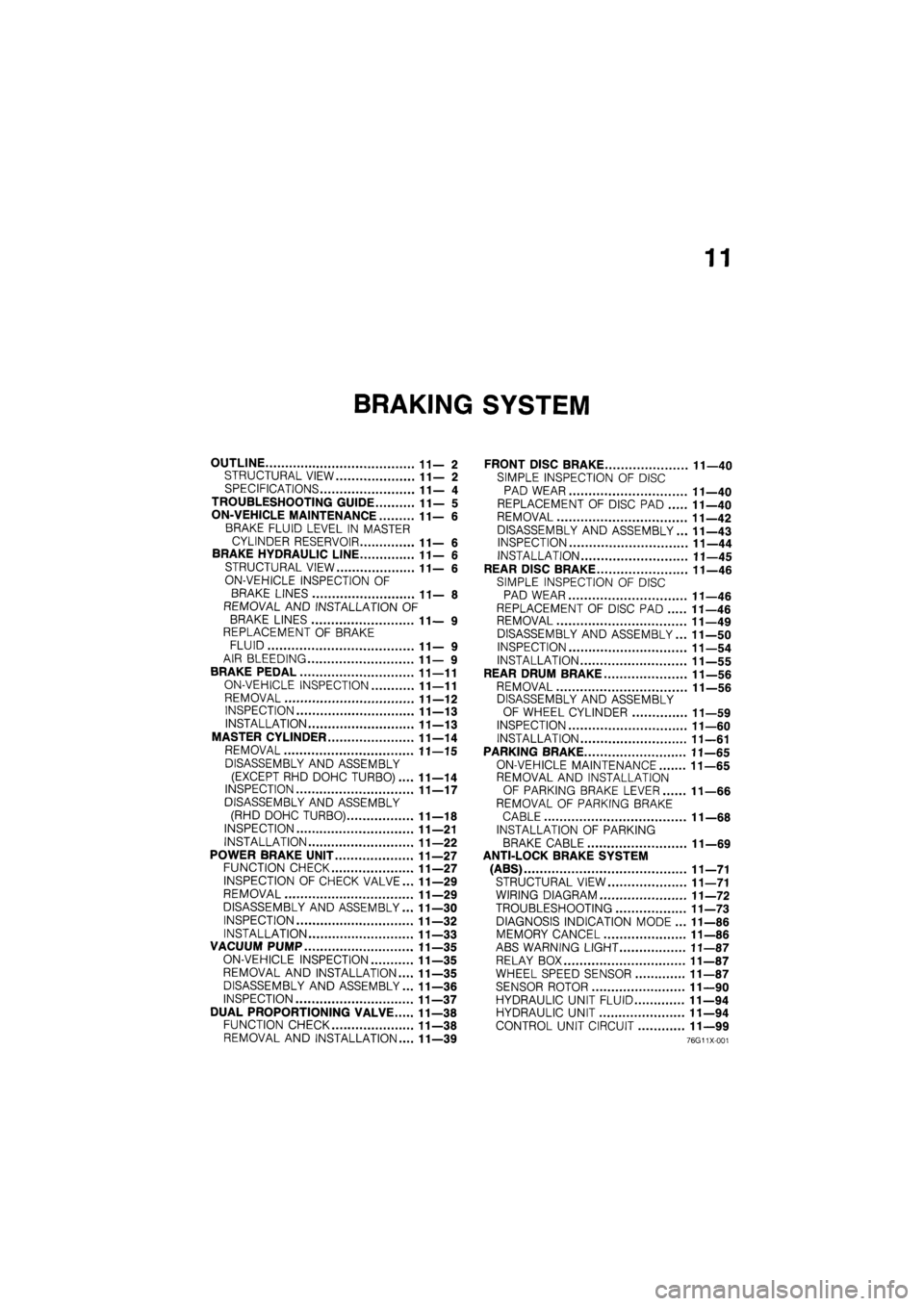
BRAKING SYSTEM
OUTLINE 11—2
STRUCTURAL VIEW 11—2
SPECIFICATIONS 11— 4
TROUBLESHOOTING GUIDE 11— 5
ON-VEHICLE MAINTENANCE 11—6
BRAKE FLUID LEVEL IN MASTER
CYLINDER RESERVOIR 11— 6
BRAKE HYDRAULIC LINE 11—6
STRUCTURAL VIEW 11—6
ON-VEHICLE INSPECTION OF
BRAKE LINES 11— 8
REMOVAL AND INSTALLATION OF
BRAKE LINES 11— 9
REPLACEMENT OF BRAKE
FLUID 11— 9
AIR BLEEDING 11— 9
BRAKE PEDAL 11—11
ON-VEHICLE INSPECTION 11—11
REMOVAL 11—12
INSPECTION 11—13
INSTALLATION 11—13
MASTER CYLINDER 11—14
REMOVAL 11—15
DISASSEMBLY AND ASSEMBLY
(EXCEPT RHD DOHC TURBO).... 11—14
INSPECTION 11—17
DISASSEMBLY AND ASSEMBLY
(RHD DOHC TURBO) 11—18
INSPECTION 11—21
INSTALLATION 11—22
POWER BRAKE UNIT 11—27
FUNCTION CHECK 11—27
INSPECTION OF CHECK VALVE... 11—29
REMOVAL 11—29
DISASSEMBLY AND ASSEMBLY... 11—30
INSPECTION 11—32
INSTALLATION 11—33
VACUUM PUMP 11—35
ON-VEHICLE INSPECTION 11—35
REMOVAL AND INSTALLATION.... 11—35
DISASSEMBLY AND ASSEMBLY... 11—36
INSPECTION 11—37
DUAL PROPORTIONING VALVE 11—38
FUNCTION CHECK 11—38
REMOVAL AND INSTALLATION.... 11—39
FRONT DISC BRAKE 11—40
SIMPLE INSPECTION OF DISC
PAD WEAR 11—40
REPLACEMENT OF DISC PAD 11—40
REMOVAL 11—42
DISASSEMBLY AND ASSEMBLY... 11—43
INSPECTION 11—44
INSTALLATION 11—45
REAR DISC BRAKE 11—46
SIMPLE INSPECTION OF DISC
PAD WEAR 11—46
REPLACEMENT OF DISC PAD 11—46
REMOVAL 11—49
DISASSEMBLY AND ASSEMBLY... 11—50
INSPECTION 11—54
INSTALLATION 11—55
REAR DRUM BRAKE 11—56
REMOVAL 11—56
DISASSEMBLY AND ASSEMBLY
OF WHEEL CYLINDER 11—59
INSPECTION 11—60
INSTALLATION 11—61
PARKING BRAKE 11—65
ON-VEHICLE MAINTENANCE 11—65
REMOVAL AND INSTALLATION
OF PARKING BRAKE LEVER 11—66
REMOVAL OF PARKING BRAKE
CABLE 11—68
INSTALLATION OF PARKING
BRAKE CABLE 11—69
ANTI-LOCK BRAKE SYSTEM
(ABS) 11—71
STRUCTURAL VIEW 11—71
WIRING DIAGRAM 11—72
TROUBLESHOOTING 11—73
DIAGNOSIS INDICATION MODE ... 11—86
MEMORY CANCEL 11—86
ABS WARNING LIGHT 11—87
RELAY BOX 11—87
WHEEL SPEED SENSOR 11—87
SENSOR ROTOR 11—90
HYDRAULIC UNIT FLUID 11—94
HYDRAULIC UNIT 11—94
CONTROL UNIT CIRCUIT 11—99
76G11X-001
Page 1394 of 1865
1 1 OUTLINE
OUTLINE
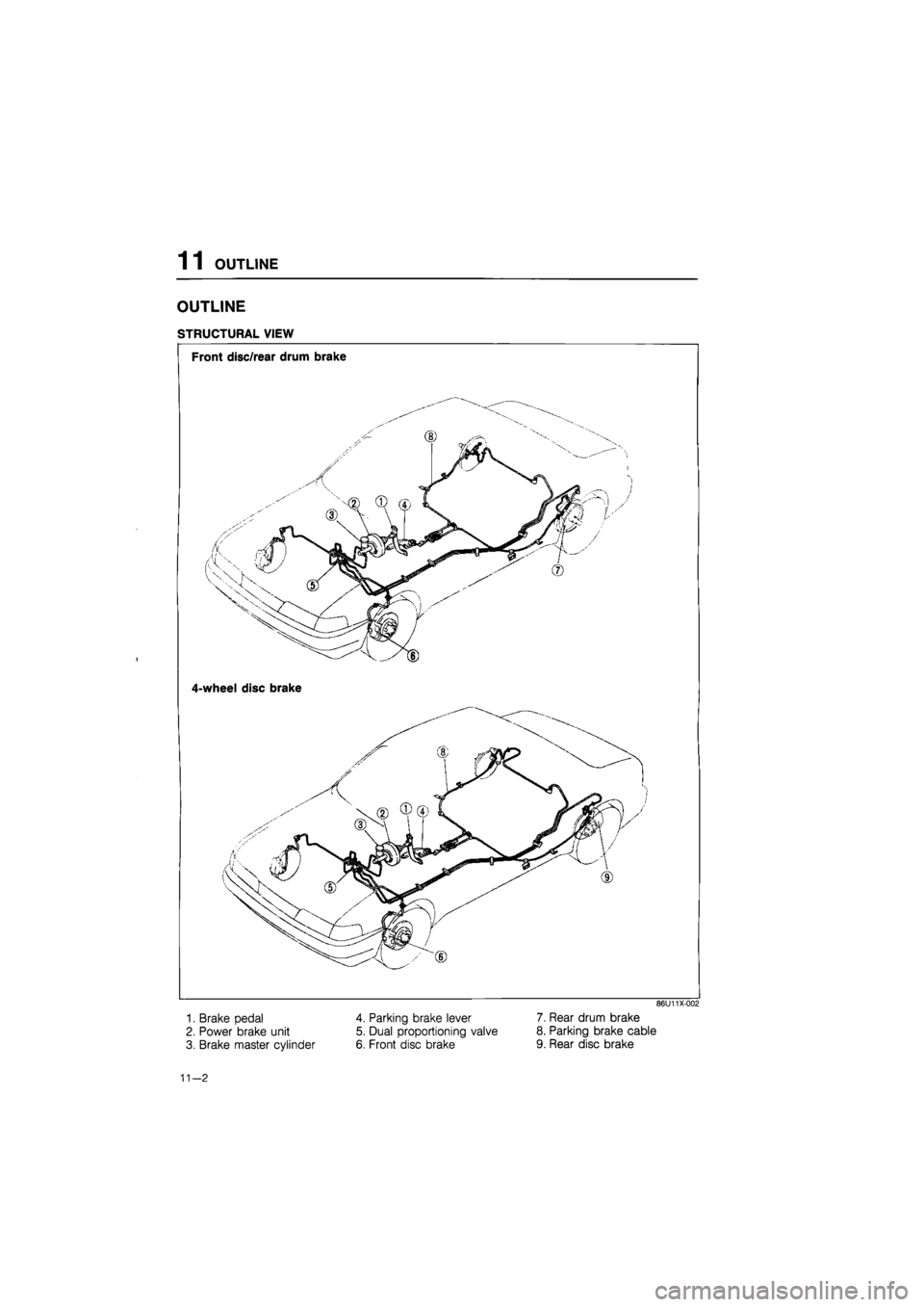
STRUCTURAL VIEW
i
Front disc/rear drum brake
4-wheel disc brake
1. Brake pedal
2. Power brake unit
3. Brake master cylinder
4. Parking brake lever
5. Dual proportioning valve
6. Front disc brake
86U11X-002
7. Rear drum brake
8. Parking brake cable
9. Rear disc brake
11—2
Page 1395 of 1865
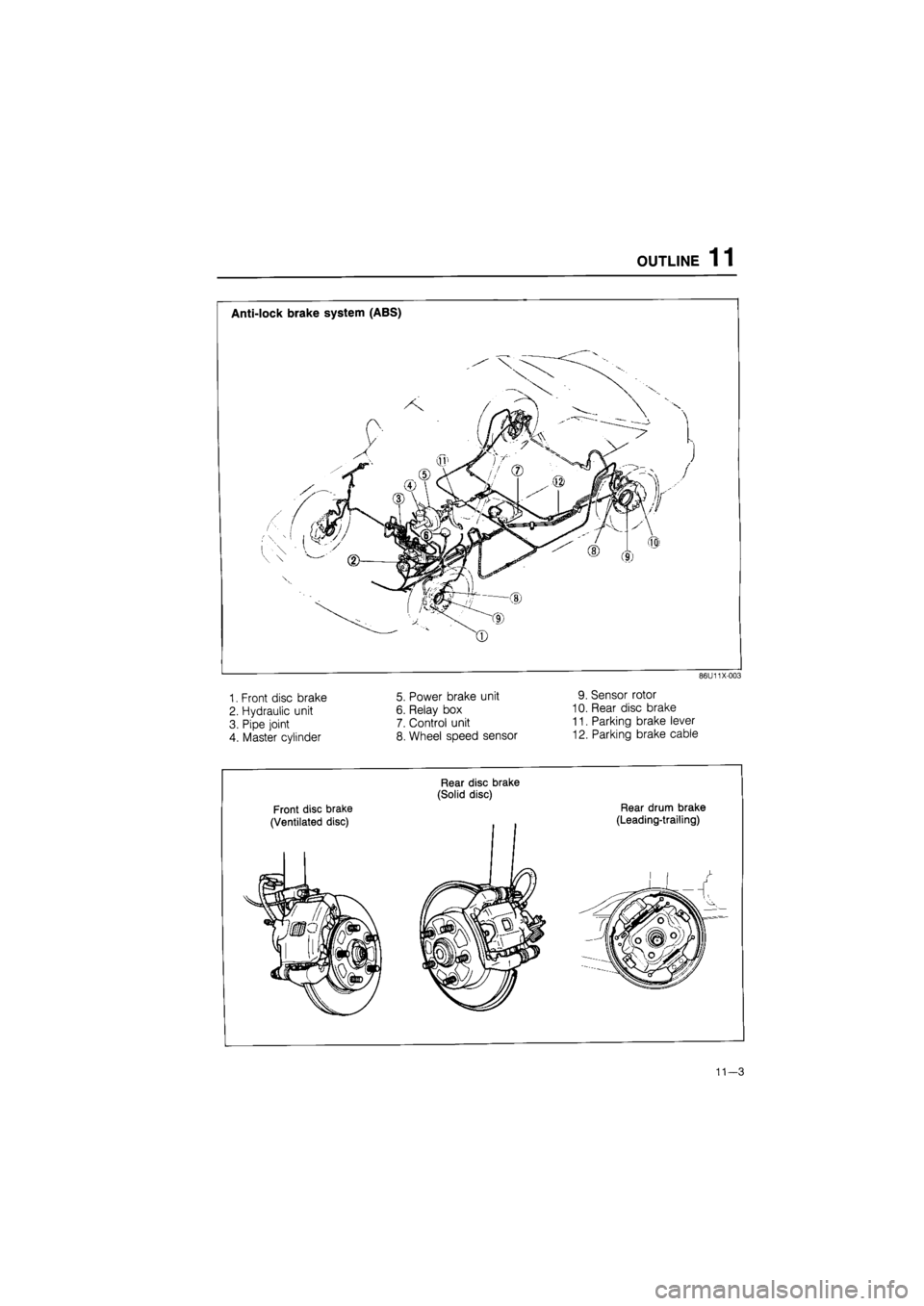
OUTLINE 11
86U11X-003
1. Front disc brake
2. Hydraulic unit
3. Pipe joint
4. Master cylinder
5. Power brake unit
6. Relay box
7. Control unit
8. Wheel speed sensor
9. Sensor rotor
10. Rear disc brake
11. Parking brake lever
12. Parking brake cable
Front disc brake
(Ventilated disc)
Rear disc brake
(Solid disc)
Rear drum brake
(Leading-trailing)
Page 1396 of 1865
1 1 OUTLINE
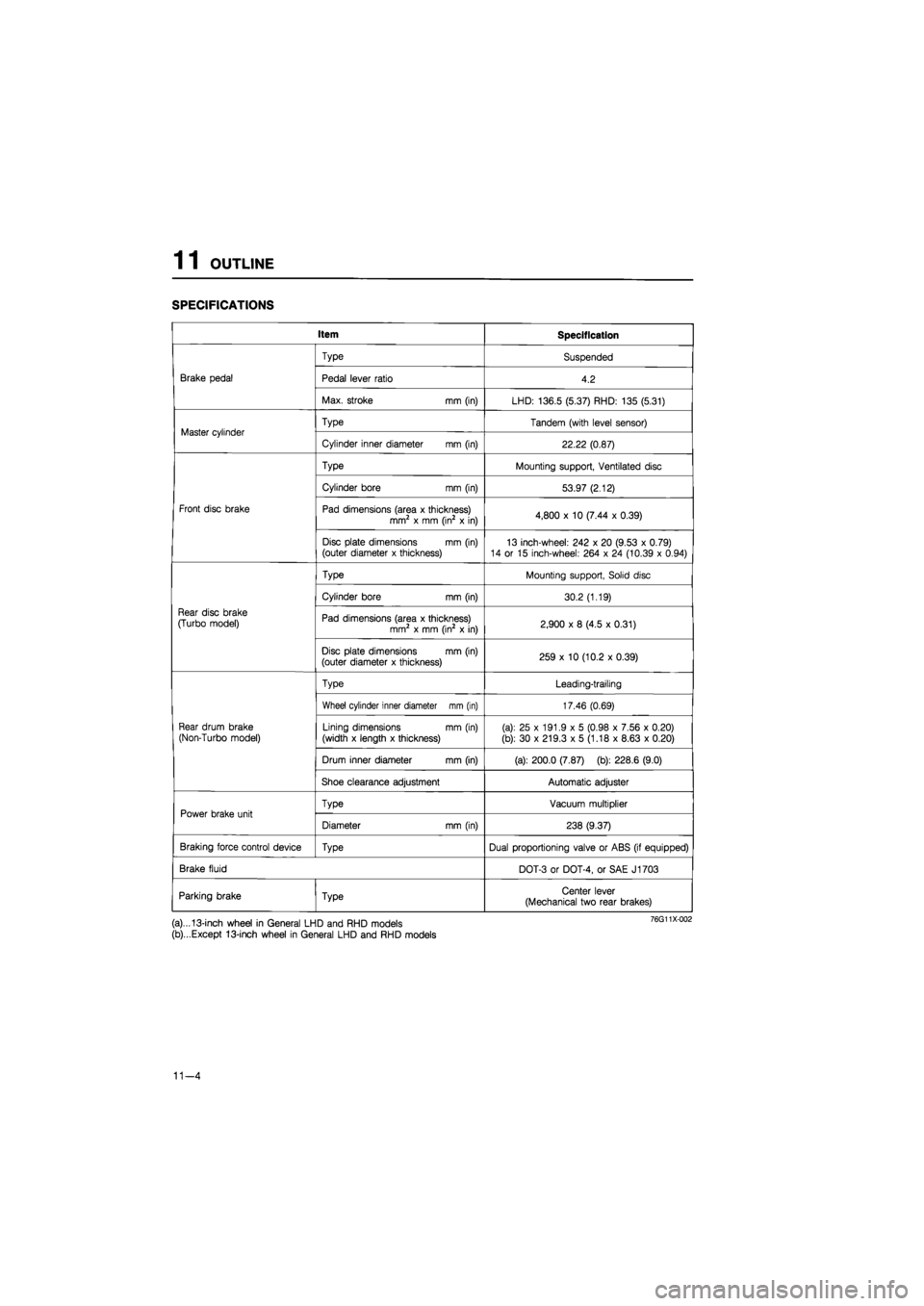
SPECIFICATIONS
Item Specification
Brake pedal
Type Suspended
Brake pedal Pedal lever ratio 4.2 Brake pedal
Max. stroke mm (in) LHD: 136.5 (5.37) RHD: 135 (5.31)
Master cylinder Type Tandem (with level sensor) Master cylinder
Cylinder inner diameter mm (in) 22.22 (0.87)
Front disc brake
Type Mounting support, Ventilated disc
Front disc brake
Cylinder bore mm (in) 53.97 (2.12)
Front disc brake Pad dimensions (area x thickness) mm2 x mm (in2 x in) 4,800 x 10 (7.44 x 0.39) Front disc brake
Disc plate dimensions mm (in) (outer diameter x thickness) 13 inch-wheel: 242 x 20 (9.53 x 0.79) 14 or 15 inch-wheel: 264 x 24 (10.39 x 0.94)
Rear disc brake
(Turbo model)
Type Mounting support, Solid disc
Rear disc brake
(Turbo model)
Cylinder bore mm (in) 30.2 (1.19)
Rear disc brake
(Turbo model) Pad dimensions (area x thickness) mm2 x mm (in2 x in) 2,900 x 8 (4.5 x 0.31)
Rear disc brake
(Turbo model)
Disc plate dimensions mm (in) (outer diameter x thickness) 259 x 10 (10.2 x 0.39)
Rear drum brake
(Non-Turbo model)
Type Leading-trailing
Rear drum brake
(Non-Turbo model)
Wheel cylinder inner diameter mm (in) 17.46 (0.69)
Rear drum brake
(Non-Turbo model) Lining dimensions mm (in)
(width x length x thickness) (a): 25 x 191.9 x 5 (0.98 x 7.56 x 0.20)
(b): 30 x 219.3 x 5 (1.18 x 8.63 x 0.20)
Rear drum brake
(Non-Turbo model)
Drum inner diameter mm (in) (a): 200.0 (7.87) (b): 228.6 (9.0)
Rear drum brake
(Non-Turbo model)
Shoe clearance adjustment Automatic adjuster
Power brake unit Type Vacuum multiplier Power brake unit
Diameter mm (in) 238 (9.37)
Braking force control device Type Dual proportioning valve or ABS (if equipped)
Brake fluid DOT-3 or DOT-4, or SAE J1703
Parking brake Type Center lever (Mechanical two rear brakes)
(a)...13-inch wheel in General LHD and RHD models
(b)...Except 13-inch wheel in General LHD and RHD models
11-4
Page 1397 of 1865
TROUBLESHOOTING GUIDE 1 1
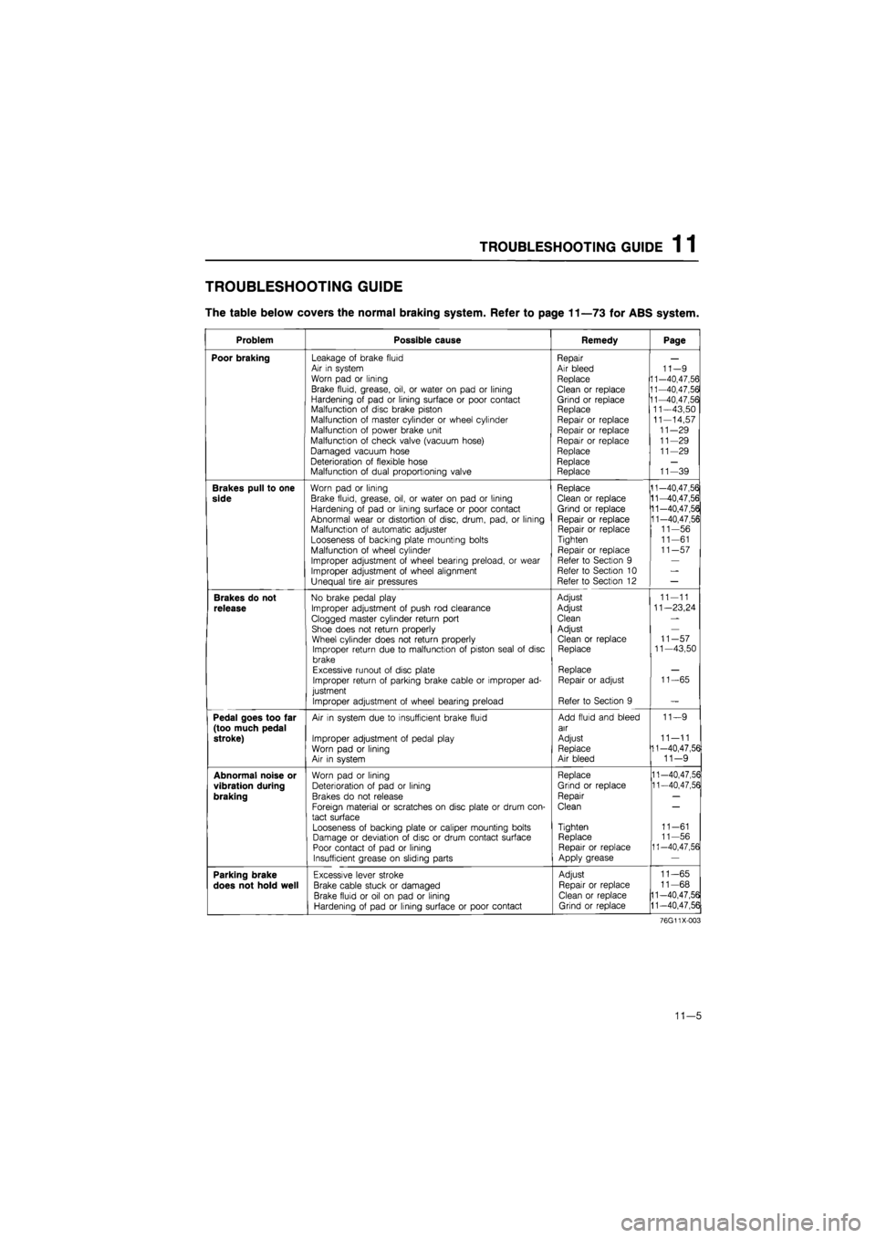
TROUBLESHOOTING GUIDE
The table below covers the normal braking system. Refer to page 11—73 for ABS system.
Problem Possible cause Remedy Page
Poor braking Leakage of brake fluid Air in system Worn pad or lining
Brake fluid, grease, oil, or water on pad or lining Hardening of pad or lining surface or poor contact Malfunction of disc brake piston Malfunction of master cylinder or wheel cylinder Malfunction of power brake unit
Malfunction of check valve (vacuum hose)
Damaged vacuum hose Deterioration of flexible hose Malfunction of dual proportioning valve
Repair Air bleed Replace
Clean or replace Grind or replace Replace Repair or replace Repair or replace Repair or replace Replace Replace Replace
11-9 11-40,47,56 11-40,47,56 11-40,47,56 11—43,50 11-14,57 11-29 11-29 11-29
11-39
Brakes pull to one
side
Worn pad or lining
Brake fluid, grease, oil, or water on pad or lining Hardening of pad or lining surface or poor contact Abnormal wear or distortion of disc, drum, pad, or lining Malfunction of automatic adjuster Looseness of backing plate mounting bolts Malfunction of wheel cylinder
Improper adjustment of wheel bearing preload, or wear Improper adjustment of wheel alignment Unequal tire air pressures
Replace Clean or replace Grind or replace Repair or replace Repair or replace Tighten
Repair or replace Refer to Section 9 Refer to Section 10 Refer to Section 12
11-40,47,56 11-40,47,56 11-40,47,56 11-40,47,56 11-56 11-61 11-57
Brakes do not
release
No brake pedal play
Improper adjustment of push rod clearance
Clogged master cylinder return port Shoe does not return properly Wheel cylinder does not return properly Improper return due to malfunction of piston seal of disc brake Excessive runout of disc plate Improper return of parking brake cable or improper ad-justment
Improper adjustment of wheel bearing preload
Adjust
Adjust
Clean
Adjust Clean or replace Replace
Replace Repair or adjust
Refer to Section 9
11-11
11—23,24
11-57 11—43,50
11-65
Pedal goes too far (too much pedal stroke)
Air in system due to insufficient brake fluid
Improper adjustment of pedal play Worn pad or lining Air in system
Add fluid and bleed air
Adjust Replace Air bleed
11—9
11—11 11-40,47,56 11-9
Abnormal noise or
vibration during
braking
Worn pad or lining Deterioration of pad or lining Brakes do not release
Foreign material or scratches on disc plate or drum con-tact surface
Looseness of backing plate or caliper mounting bolts Damage or deviation of disc or drum contact surface Poor contact of pad or lining Insufficient grease on sliding parts
Replace
Grind or replace
Repair
Clean
Tighten Replace Repair or replace Apply grease
11-40,47,56 11-40,47,56
11-61 11-56 11-40,47,56
Parking brake
does not hold well
Excessive lever stroke
Brake cable stuck or damaged
Brake fluid or oil on pad or lining Hardening of pad or lining surface or poor contact
Adjust
Repair or replace Clean or replace Grind or replace
11-65
11-68
11-40,47,56
11-40,47,56
76G11X-003
11—5