Page 1671 of 1865

1 5 COMBINATION SWITCH
Steering angle sensor
Terminal Steering wheel position Resistance value
AO
to
AR Turn the wheel
a
little
at
a
time from
the
straight-ahead posi-
tion 180° to the right.
Decreases from about
25 kfi to about 200
fl.
AO
to
AR Straight-ahead position About
25 kfi
AO
to
AR Turn the wheel
a
little at
a
time from
the
straight-ahead posi-tion 180°
to
the left.
Increases from about 25 kfl to about 50 kfl.
AL
to
AR Straight-ahead position About
50 kfi
86U15X-014
—
i 50kn k Resistance
25M?
2000
" 180° 0° 180° " To the left To the right
86U15X-015
Note
When the steering wheel is turned more than
the specified angle in the above test, the re-
sistance value will become as shown in the
table below.
Terminal Steering wheel position Resistance value
AO
to
AR When turned 180°
or
more to the right from the straight-ahead po-sition.
Resistance slowly and gradually decreases after there
is
once
an
indication of about 50 kfl.
AO
to
AR When turned 180°
or
more
to
the left from
the straight-ahead po-
sition.
Resistance slowly and gradually increases after there
is
once
an
indication
of
about 200
fl.
15—16
Page 1749 of 1865

1 5 AUTO ADJUSTING SUSPENSION (AAS)
AUTO ADJUSTING SUSPENSION (AAS)
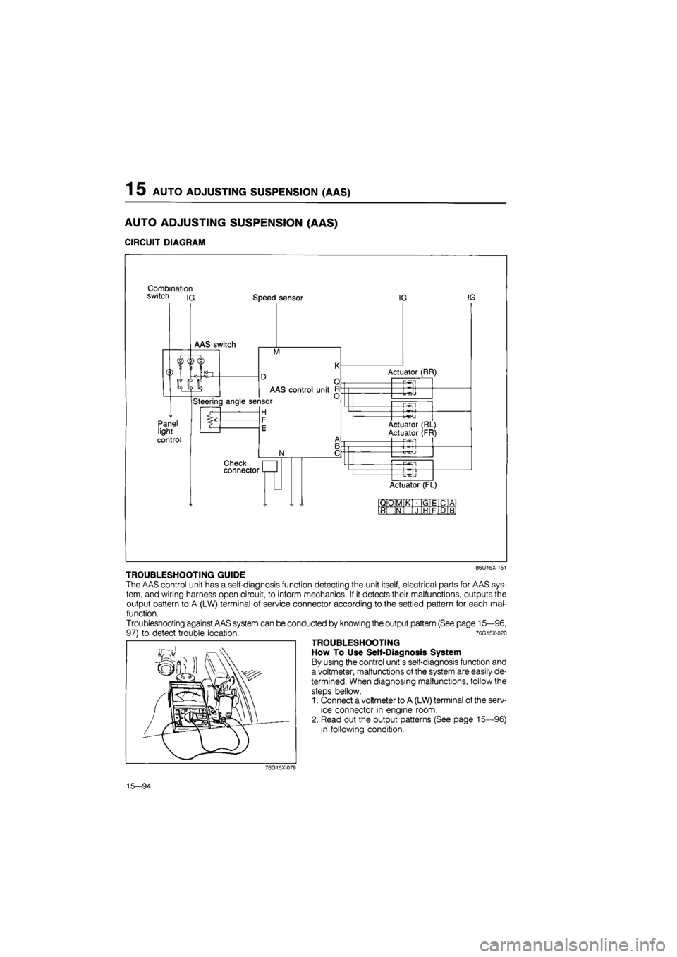
CIRCUIT DIAGRAM
Combination switch iq Speed sensor
M
Panel light
control
AAS control unit
Steering angle sensor
H
N
Check connector
IG IG
Actuator (RR)
-P-Sl
-t-^J
—Pwsl
Actuator (RL)
Actuator (FR) P5fl
+
Actuator (FL)
QO M K GIE C A
ft N J HI F D B
86U15X-151
TROUBLESHOOTING GUIDE
The AAS control unit has a self-diagnosis function detecting the unit itself, electrical parts for AAS sys-
tem, and wiring harness open circuit, to inform mechanics. If it detects their malfunctions, outputs the
output pattern to A (LW) terminal of service connector according to the settled pattern for each mal-
function.
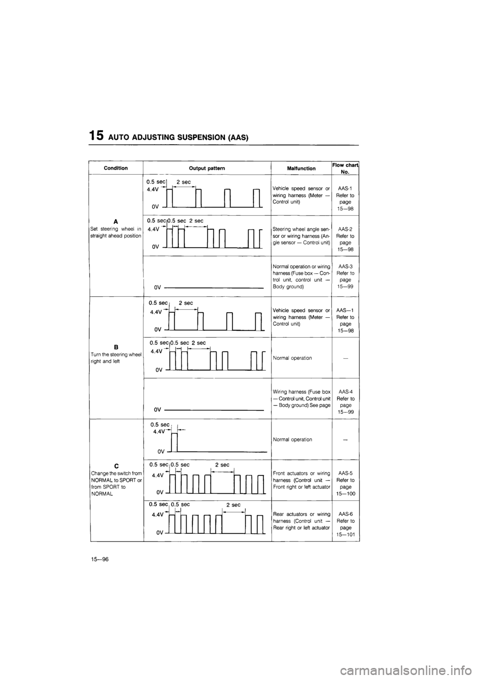
Troubleshooting against AAS system can be conducted by knowing the output pattern (See page 15—96,
97) to detect trouble location. 76gisx-o2o
TROUBLESHOOTING
How To Use Self-Diagnosis System
By using the control unit's self-diagnosis function and
a voltmeter, malfunctions of the system are easily de-
termined. When diagnosing malfunctions, follow the
steps bellow.
1. Connect a voltmeter to A (LW) terminal of the serv-
ice connector in engine room.
2. Read out the output patterns (See page 15—96)
in following condition.
76G15X-079
15—94
Page 1750 of 1865
AUTO ADJUSTING SUSPENSION (AAS) 1 5
Checking Condition
Note:
Turn the ignition switch OFF to reset the con-
trol unit before each test.
Condition A
1. Turn the ignition switch ON.
2. Set steering wheel in the straight-ahead position,
and check the output pattern.
86U15X-154
Condition B
1. Turn the ignition switch ON.
2. Turn the steering wheel right and left, and check
the output pattern.
86U15X-155
•
/
AUTO ADJUSTING SUSPENSION I- AUTO—i SOFT NORMAL SPORT
Condition C
1. Turn the ignition switch ON.
2. Change the AAS switch from NORMAL to SPORT
or from SPORT to NORMAL, and check the out-
put pattern.
86U15X-156
Condition D
1. Operate the vehicle on a chassis roller.
2. Check the output pattern at above 15 km/h (9.3
mph).
Caution
a) Block the rear wheels.
b) In vehicle equipped with ABS, ABS warn-
ing light may come on, which is not a fail-
ure. The light goes off by turning ignition
switch OFF and again ON.
86U15X-157
15—95
Page 1751 of 1865

1 5 AUTO ADJUSTING SUSPENSION (AAS)
Condition Output pattern Malfunction Flow chart
No.
A
Set steering wheel
in
straight ahead position
0.5 sec
4.4V
n\/
2 sec
Vehicle speed sensor
or
wiring harness (Meter
—
Control unit)
AAS-1
Refer
to
page
15—98
A
Set steering wheel
in
straight ahead position
Vehicle speed sensor
or
wiring harness (Meter
—
Control unit)
AAS-1
Refer
to
page
15—98
A
Set steering wheel
in
straight ahead position
0.5 secO.!
4.4V
nv
i sec
2
sec
— <—i i— -
Steering wheel angle sen-
sor
or
wiring harness (An-
gle sensor
—
Control unit)
AAS-2
Refer
to
page
15-98
A
Set steering wheel
in
straight ahead position
-
Steering wheel angle sen-
sor
or
wiring harness (An-
gle sensor
—
Control unit)
AAS-2
Refer
to
page
15-98
A
Set steering wheel
in
straight ahead position
nv
Normal operation or wiring
harness (Fuse box
—
Con-
trol unit, control unit
—
Body ground)
AAS-3
Refer
to
page
15-99
A
Set steering wheel
in
straight ahead position
Normal operation or wiring
harness (Fuse box
—
Con-
trol unit, control unit
—
Body ground)
AAS-3
Refer
to
page
15-99
B
Turn the steering wheel
right and left
0.5 sec
4.4V
n\/
2 sec
—
Vehicle speed sensor
or
wiring harness (Meter
—
Control unit)
AAS-1
Refer
to
page
15-98
B
Turn the steering wheel
right and left
Vehicle speed sensor
or
wiring harness (Meter
—
Control unit)
AAS-1
Refer
to
page
15-98
B
Turn the steering wheel
right and left
0.5 sec 0
4.4V""-
.5 se c 2 se
-
Normal operation
—
B
Turn the steering wheel
right and left Normal operation
—
B
Turn the steering wheel
right and left
ov
Wiring harness (Fuse box
— Control unit, Control unit
— Body ground) See page
AAS-4
Refer
to
page
15—99
B
Turn the steering wheel
right and left
Wiring harness (Fuse box
— Control unit, Control unit
— Body ground) See page
AAS-4
Refer
to
page
15—99
C
Change the switch from
NORMAL to SPORT
or
from SPORT
to
NORMAL
0.5 sec
4.4V-""
_
n
Normal operation
—
C
Change the switch from
NORMAL to SPORT
or
from SPORT
to
NORMAL
Normal operation
—
C
Change the switch from
NORMAL to SPORT
or
from SPORT
to
NORMAL
0.5 sec 0
4.4V
nv
.5 se c
—
2 se
C
i—1 i—i
Front actuators
or
wiring
harness (Control unit
—
Front right
or
left actuator
AAS-5
Refer
to
page
15-100
C
Change the switch from
NORMAL to SPORT
or
from SPORT
to
NORMAL
Front actuators
or
wiring
harness (Control unit
—
Front right
or
left actuator
AAS-5
Refer
to
page
15-100
C
Change the switch from
NORMAL to SPORT
or
from SPORT
to
NORMAL
0.5 sec 0
4.4V*-
n\/
.5 se c
— r— —
2 sec
—1
Rear actuators
or
wiring
harness (Control unit
—
Rear right
or
left actuator
AAS-6
Refer
to
page
15-101
C
Change the switch from
NORMAL to SPORT
or
from SPORT
to
NORMAL
Rear actuators
or
wiring
harness (Control unit
—
Rear right
or
left actuator
AAS-6
Refer
to
page
15-101
15-96
Page 1752 of 1865
AUTO ADJUSTING SUSPENSION (AAS) 1 5
C
(Cont'd)
Operate
the
vehicle
at
above
15 km/h (9.3
mph) on
a
chassis roller
OV-
4.4V
0V-
4.4V
OV-
OV
AAS switch
or
wiring har-
ness (Fuse box
—
Control
box and AAS switch, AAS
switch
—
Control box and
Body ground)
Normal operation
Speed sensor
or
Steering
wheel angle sensor
or
wir-
ing harness (Control unit
—
Meter, Control unit
—
An-
gle sensor)
Speed sensor
or
Wiring
harness (Control unit
—
Meter, Fuse box
—
Control
unit, Control unit
—
Body
ground)
76G15X-080
15-97
Page 1753 of 1865
1 5 AUTO ADJUSTING SUSPENSION
Inspection of circuit
OK
Check
for
continuity between
1U
(GR) terminal
of
the meter connector and
M
(GR) terminal
of
the control unit connector.
Repair the wiring harness (Control unit
to
Meter).
OK
Replace the control unit.
76G15X-081
AAS-2
Failure
of
steering wheel angle sensor
or wiring harness (Angle sensor
—
Control unit)
I
Disconnect the control unit connector, and check
the
resistance between the terminals with
an
ohmmeter
when steering wheel
in
straight ahead position.
Terminal Resistance
A(G)
-
D(GW) ADDrox.
25 kfi
A(G)
-
C(GY) Approx.
50 kfl
C(GY^
-
D(G\M ADorox.
25 kfi
OK
Replace the control unit.
76G15X-082
15-98
Page 1757 of 1865

1 5 AUTO ADJUSTING SUSPENSION
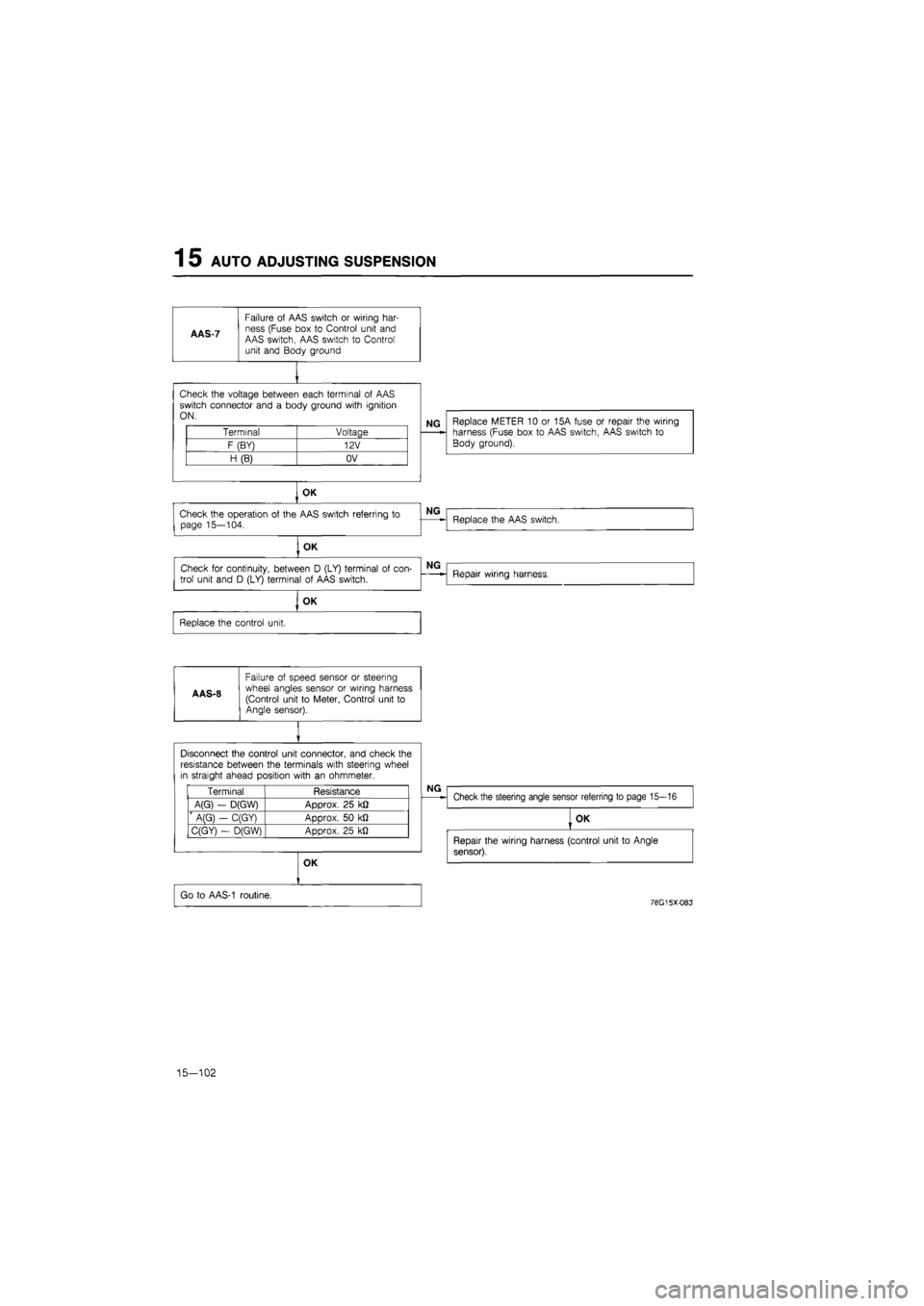
AAS-7
Failure
of
AAS switch
or
wiring har-ness (Fuse box
to
Control unit and AAS switch, AAS switch
to
Control unit and Body ground
Check the voltage between each terminal
of
AAS switch connector and
a
body ground with ignition ON.
Terminal Voltage
F (BY) 12V
H (B) OV
NG Replace METER
10 or
15A fuse
or
repair the wiring harness (Fuse box
to
AAS switch, AAS switch
to
Body ground).
OK
Check the operation
of
the AAS switch referring
to
page 15—104.
, OK
Check
for
continuity, between
D
(LY) terminal
of
con-
trol unit and
D
(LY) terminal
of
AAS switch.
OK
Replace the control unit.
A AS-8
Failure
of
speed sensor
or
steering wheel angles sensor
or
wiring harness (Control unit
to
Meter, Control unit
to
Angle sensor).
NG
Replace the AAS switch.
NG
Repair wiring harness.
Disconnect the control unit connector, and check the resistance between the terminals with steering wheel in straight ahead position with
an
ohmmeter.
Terminal Resistance
A(G)
-
D(GW) Approx.
25
k£2
' A(G}
-
C(GY) Approx.
50 kfl
C(GY)
-
D(GW) Approx.
25
kJ2
NG
Check the steering angle sensor referring
to
page 15—16
OK
Go
to
AAS-1 routine.
OK
Repair the wiring harness (control unit
to
Angle
sensor).
76G15X-083
15-102
Page 1759 of 1865
1 5 AUTO ADJUSTING SUSPENSION
Actuator
Inspection
1. Turn the ignition switch ON.
2. Alternately switch ON the "NORMAL" and
"SPORT" switches. Check whether the shaft of the
actuator installed on the front and rear damper
operates. (Visual inspection)
86U15X-167
86U15X-168
76G15X-095
3. If the actuator does not operate, disconnect the ac-
tuator connector and check for a few ohms resis-
tance between the terminals.
Terminal Resistance
A(WR) - D(BR)
Front B(WL) - D(BR)
C(WR) - D(BR) 2-8 (fi) A(YR) - D(BR) 2-8 (fi)
Rear B(YG) - D(BR)
C(YL)— D(BR)
AAS Switch
Inspection
1. Use an ohmmeter to check continuity of the termi-
nals of the switch.
2. If continuity is not as specified, replace the switch.
Position Terminal
SOFT
NORMAL
SPORT
O
o—o
-o
o
o
o
o
g
-o
-o -o
O
O: Indicates continuity
Steering Wheel Angle Sensor
Inspection
See page 15—16
Vehicle Speed Sensor
Inspection
See page 15—88
76G15X-085
15—104