Page 1481 of 1865
ANTI-LOCK BRAKE SYSTEM (ABS) 1 1
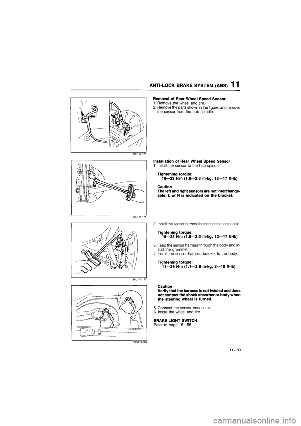
Removal of Rear Wheel Speed Sensor
1. Remove the wheel and tire.
2. Remove the parts shown in the figure, and remove
the sensor from the hub spindle.
86U11X-173
86U11X-174
86U11X-175
Installation of Rear Wheel Speed Sensor
1. Install the sensor to the hub spindle.
Tightening torque:
16—23 N m (1.6—2.3 m-kg, 12—17 ft-lb)
Caution
The left and right sensors are not interchange-
able. L or R is indicated on the bracket.
2. Install the sensor harness bracket onto the knuckle.
Tightening torque:
16—23 Nm (1.6—2.3 m-kg, 12—17 ft-lb)
3. Feed the sensor harness through the body and in-
stall the gromrnet.
4. Install the sensor harness bracket to the body.
Tightening torque:
11—26 N m (1.1—2.6 m-kg, 8—19 ft-lb)
Caution
Verify that the harness is not twisted and does
not contact the shock absorber or body when
the steering wheel is turned.
5. Connect the sensor connector.
6. Install the wheel and tire.
BRAKE LIGHT SWITCH
Refer to page 15—58.
76G11X-060
11-89
Page 1493 of 1865
1 2 OUTLINE, TROUBLESHOOTING GUIDE
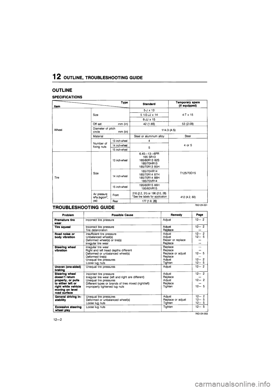
OUTLINE
SPECIFICATIONS
Type
Item Standard Temporary spare (if equipped)
Wheel
Size
5-J
x 13
4-T
x 15
Wheel
Size 5 1/2-JJ
x 14
4-T
x 15
Wheel
Size
6-JJ
x 15
4-T
x 15
Wheel
Off set mm (in) 42 (1.65) 53 (2.09)
Wheel Diameter
of
pitch circle
mm
(in) 114.3 (4.5) Wheel
Material Steel
or
aluminum alloy Steel
Wheel
Number
of
fixing nuts
13 inch-wheel 4
4
or 5
Wheel
Number
of
fixing nuts 14 inch-wheel 5 4
or 5
Wheel
Number
of
fixing nuts 15 inch-wheel 5 4
or 5
Tire
Size
13 inch-wheel
6.45—13—6PR
165 SR13 165/80R13 82S 185/70HR13 185/70R13 85H
T125/70D15
Tire
Size 14 inch-wheel
185/70HR14 185/70R14 87H 185/70R14 88H 185/70VR14
T125/70D15
Tire
Size
15 inch-wheel 195/60R15 86H
195/60VR15
T125/70D15
Tire
Air pressure
kPa (kg/cm2,
psi)
Front 216 (2.2, 31) or 196 (2.0, 28) "See tire labels for application 412(4.2, 60)
Tire
Air pressure
kPa (kg/cm2,
psi) Rear 177 (1.8, 26)
412(4.2, 60)
TROUBLESHOOTING GUIDE 76G12X-001
Problem Possible Cause Remedy Page
Premature tire wear
Incorrect tire pressure Adjust 12-
2
Tire squeal
Incorrect tire pressure Tire deterioration
Adjust ReDlace
12-
2
Road noise or body vibration
Insufficient tire pressure Unbalanced wheel(s) Deformed wheel(s)
or
tire(s) Irregular tire wear
Adjust Adjust Repair
or
replace Reolace
-1
12-
2
12-
5
Steering wheel vibration
Irregular tire wear Right and left tread depths different Deformed
or
unbalanced wheel(s) Deformed tire(s) Unequal tire pressures Loose lug nuts
Replace Replace
Replace
or
adjust Replace Adjust Tiahten
12-
5
12—
2
12-
5
Uneven (one-sided) braking
Unequal tire pressures Adjust 12-
2
Steering wheel doesn't return properly, or pulls to either left or right while vehicle moving on level road surface
Incorrect tire pressure Irregular tire wear (left and right are different) Unequal tire pressures Different types
or
brands
of
tires mixed (right/left) Improperly tightened lug nuts
Adjust Replace Adjust Replace Tighten
12-
2
12—
2
12-
5
General driving in-stability
Unequal tire pressures Deformed
or
unbalanced wheel(s) Loose lug nuts
Adjust Replace
or
adjust Tiahten
12-
2
12-
5
12-
5
Excessive steering wheel play
Loose lug nuts Tighten 12-
5
76G12X-002
12-2
Page 1500 of 1865
OUTLINE 13
Rear Suspension
4-wheel steering (4WS)
86U13X-003
13—3
Page 1501 of 1865
13 OUTLINE
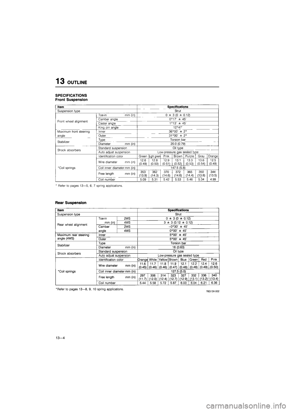
SPECIFICATIONS
Front Suspension
Item Specifications
Suspension type Strut
Toe-in mm (in) 0 ± 3 (0 ± 0.12)
Front wheel alignment Camber angle 0C 17' ± 45' Front wheel alignment Caster angle 1c 13' ± 45'
King pin angle 12°47'
Maximum front steering Inner 36 °00' ± 2°
angle Outer 31 °00' ± 2°
Stabilizer Type Torsion bar Stabilizer Diameter mm (in) 20.0 (0.79)
Shock absorbers Standard suspension Oil type Shock absorbers Auto adjust suspension Low-pressure gas sealed type
Identification color Green Light green Pink Brown Purple Gray Orange
Wire diameter mm (in) 12.6 (0.49) 12.8 (0.50)
12.9
(0.51) 13.1 (0.52)
13.3 (0.53)
13.6
(0.54) 12.5 (0.49)
*Coil springs Coil inner diameter mm (in) 147.5 (5.8)
Free length mm (in) 353 (13.9)
362 (14.3) 370 (14.6) 372 (14.6) 365 (14.4)
350
(13.8)
344
(13.5)
Coil number 5.09 5.31 5 42 5.53 5.46 5.34 4.99
* Refer to pages 13—5, 6, 7 spring applications.
Rear Suspension
Item Specifications
SusDension tvDe Strut
Rear wheel alignment
Toe-in
mm (in)
2WS 0 ± 3 (0 ± 0.12)
Rear wheel alignment
Toe-in
mm (in) 4WS 3 ± 3 (0.12 ± 0.12) Rear wheel alignment Camber
anale
2WS -0°30' ± 45' Rear wheel alignment Camber
anale 4WS 0°00' ± 45'
Maximum rear steering angle (4WS) Inner 5°00' ± 45' Maximum rear steering angle (4WS) Outer 5°00' ± 45'
Stabilizer TvDe Torsion bar Stabilizer Diameter mm (in) 16 (0.63)
Shock absorbers Standard susDension Oil tvDe Shock absorbers Auto adiust suspension Low-pressure c las sealed type
'Coil springs
Identification color Orange White Yellow Brown Blue Green Red Pink
'Coil springs
Wire diameter mm (in) 11.6
(0.45)
11.7 (0.46) 11.8
(0.46)
11.9 (0.47)
12.1
(0.48)
12.2
(0.48)
12.4 (0.49) 12.6 (0.50)
'Coil springs Coil inner diameter mm (in) 127.5 (5.0) 'Coil springs
Free length mm (in) 297 (11.7) 306 (12.0)
314 (12.4) 323 (12.7) 327 (12.9) 332 (13.1) 336 (13.21 340 (13.4)
'Coil springs
Coil number 5.44 5.58 5.72 5.87 6.03 6.04 6.21 6.36
'Refer to pages 13—8, 9, 10 spring applications.
13—4
Page 1502 of 1865
OUTLINE 13
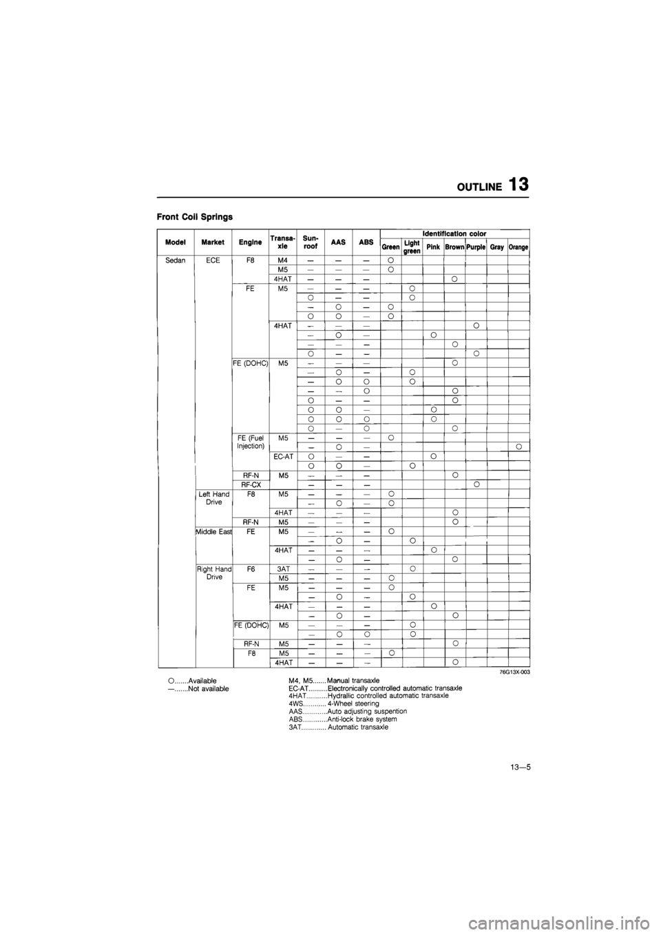
Front Coil Springs
Transa-
xle
Sun-
roof
Identification color
Model Market Engine Transa-
xle
Sun-
roof AAS ABS Green Light
green Pink Brown Purple Gray Orange
Sedan ECE F8 M4 — — — O
M5 — — — 0
4HAT — — — O
FE M5 — — — O
0 — — O
— o — o
o o — o
4HAT -— — o
— o — O
— — — o
o — — o
FE (DOHC) M5 — — — o
— o — 0
— o o o
— — o o
0 — — o
o o — o
0 0 o o
o — 0 o
FE (Fuel M5 — — — o
Injection) — 0 — O
EC-AT O — — o
o o — o
RF-N M5 — — — 0
RF-CX — — — o
Left Hand F8 M5 — — — o
Drive „ o — o
4HAT — — — o
RF-N M5 — — — o
Middle East FE M5 — — — o
-o — o
4HAT — — — o
— o — 0
Right Hand F6 3AT — — — 0
Drive M5 — — — o
FE M5 — — — 0
— o _ o
4HAT — — — o
— 0 — o
FE (DOHC) M5 — — — o
— o o 0
RF-N M5 — — — o
F8 M5 — — — 0
4HAT — — — o
76G13X003
O Available M4, M5.... ...Manual transaxle
— Not available EC-AT ....Electronically controlled automatic transaxle 4HAT ....Hydrallic controlled automatic transaxle
4WS ... 4-Wheel steering
AAS ....Auto adjusting suspention ABS ....Anti-lock brake system
3AT ... Automatic transaxle
13—5
Page 1505 of 1865
13 OUTLINE
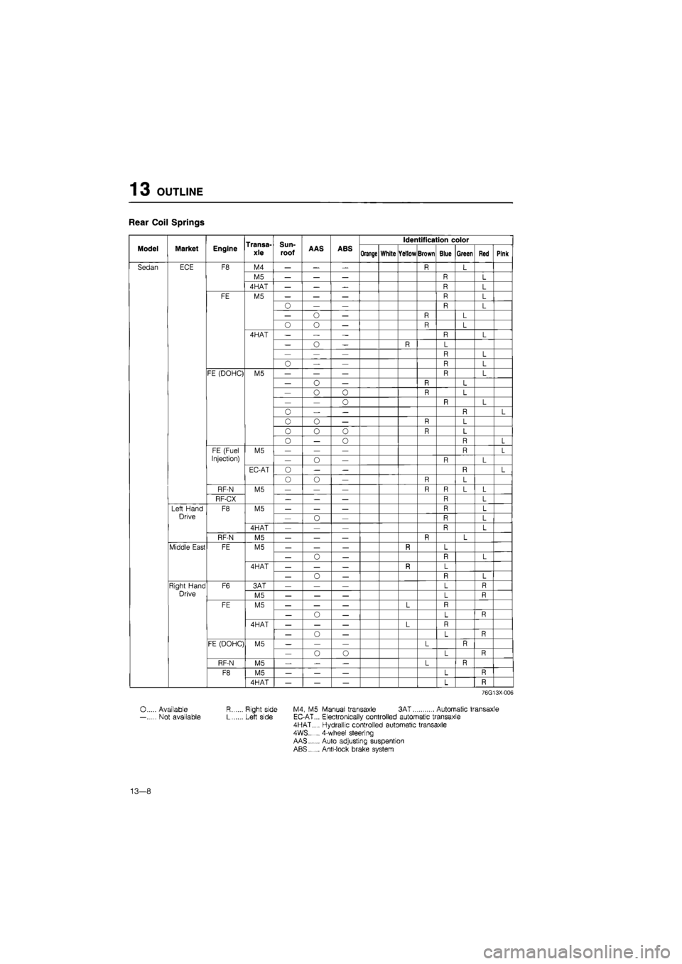
Rear Coil Springs
Transa-xle
Sun-
roof
Identification color
Model Market Engine Transa-xle
Sun-
roof AAS ABS Orange White Yellow Brown Blue Green Red Pink
Sedan ECE F8 M4 — — — R L
M5 — — — R L
4HAT — — R L
FE M5 — — — R L
— — R L
— o — R L
O 0 — R L
4HAT — „ — R L
— 0 — R L
— — — R L
o — — R L
FE (DOHC) M5 — — — R L
— o — R L
— o 0 R L
— — o R L
0 — — R L
0 o — R L
o 0 0 R L
o — o R L
FE (Fuel M5 — — — R L
Injection) — o — R L
EC-AT o — — R L
o o — R L
RF-N M5 — — — R R L L
RF-CX _ — — R L
Left Hand F8 M5 — — — R L
Drive — o — R L
4HAT — — — R L
RF-N M5 — — — R L
Middle East FE M5 — — — R L
— o — n L
4HAT — — — R L
— o — L
Right Hand F6 3AT — — — L R
Drive M5 — — — L R
FE M5 — — — L
— o — L R
4HAT — — — L
— o — L R
FE (DOHC) M5 — — — L R — o o L R
RF-N M5 — — L R
F8 M5 — — — L R
4HAT — — — L R
76G13X-006
0 Available R Right side M4, M5 Manual transaxle 3AT Automatic transaxle — Not available L Left side EC-AT... Electronically controlled automatic transaxle 4HAT..., Hydrallic controlled automatic transaxle 4WS...... 4-wheef steering AAS Auto adjusting suspention ABS Anti-lock brake system
13-8
Page 1508 of 1865
TROUBLESHOOTING GUIDE 1 3
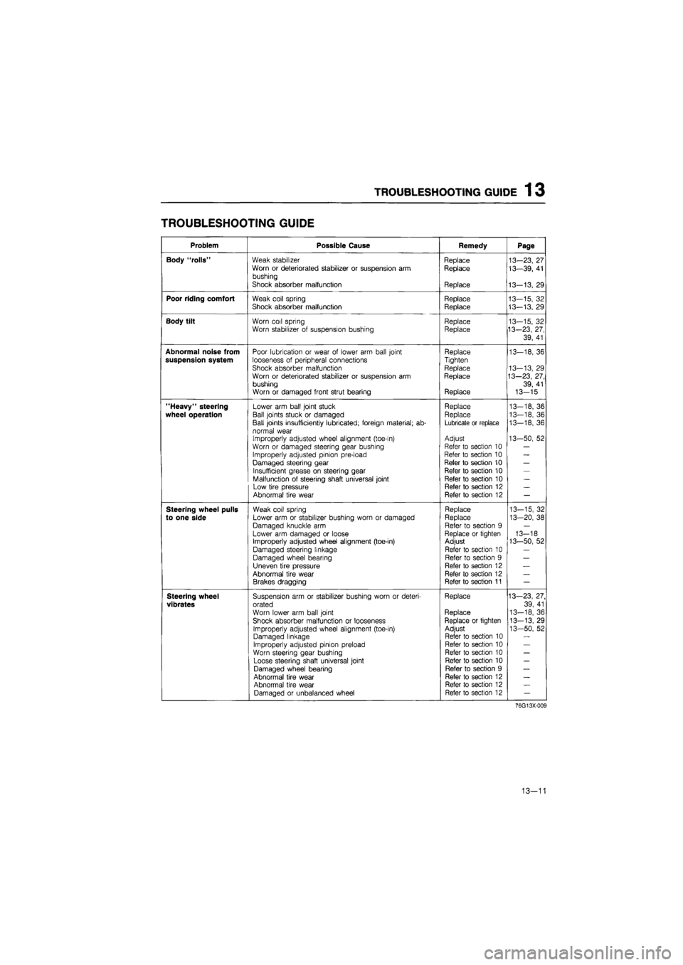
TROUBLESHOOTING GUIDE
Problem Possible Cause Remedy Page
Body "rolls" Weak stabilizer Replace 13-23, 27 Worn or deteriorated stabilizer or suspension arm Replace 13—39, 41 bushing
Shock absorber malfunction Replace 13-13, 29
Poor riding comfort Weak coil spring Replace 13-15, 32 Shock absorber malfunction Replace 13-13. 29
Body tilt Worn coil spring Replace 13-15, 32 Worn stabilizer of suspension bushing Replace 13-23, 27,
39, 41
Abnormal noise from Poor lubrication or wear of lower arm ball joint Replace 13-18, 36 suspension system looseness of peripheral connections Tighten
Shock absorber malfunction Replace 13-13, 29 Worn or deteriorated stabilizer or suspension arm Replace 13—23, 27, bushing 39, 41 Worn or damaged front strut bearing Replace 13-15
"Heavy" steering Lower arm ball joint stuck Replace 13—18, 36
wheel operation Ball joints stuck or damaged Replace 13-18, 36
Ball joints insufficiently lubricated; foreign material; ab-Lubricate or replace 13-18, 36
normal wear Improperly adjusted wheel alignment (toe-in) Adjust 13-50, 52
Worn or damaged steering gear bushing Refer to section 10 —
Improperly adjusted pinion pre-load Refer to section 10 —
Damaged steering gear Refer to section 10 —
Insufficient grease on steering gear Refer to section 10 —
Malfunction of steering shaft universal joint Refer to section 10 —
Low tire pressure Refer to section 12 —
Abnormal tire wear Refer to section 12 —
Steering wheel pulls Weak coil spring Replace 13-15, 32
to one side Lower arm or stabilizer bushing worn or damaged Replace 13-20, 38
Damaged knuckle arm Refer to section 9 —
Lower arm damaged or loose Replace or tighten 13-18 Improperly adjusted wheel alignment (toe-in) Adjust 13-50, 52
Damaged steering linkage Refer to section 10 —
Damaged wheel bearing Refer to section 9 —
Uneven tire pressure Refer to section 12 —
Abnormal tire wear Refer to section 12 —
Brakes dragging Refer to section 11 —
Steering wheel Suspension arm or stabilizer bushing worn or deteri-Replace 13—23, 27.
vibrates orated 39, 41
Worn lower arm ball joint Replace 13-18, 36
Shock absorber malfunction or looseness Replace or tighten 13-13, 29
Improperly adjusted wheel alignment (toe-in) Adjust 13-50, 52 Damaged linkage Refer to section 10
Improperly adjusted pinion preload Refer to section 10
Worn steering gear bushing Refer to section 10 —
Loose steering shaft universal joint Refer to section 10 —
Damaged wheel bearing Refer to section 9 —
Abnormal tire wear Refer to section 12 —
Abnormal tire wear Refer to section 12 —
Damaged or unbalanced wheel Refer to section 12 —
76G13X-009
13—11
Page 1509 of 1865
1 3 TROUBLESHOOTING GUIDE
Problem Possible Cause Remedy Page
Excessive steering wheel play
Worn or damaged lower arm bushing
Improperly adjusted pinion preload
Worn rack and pinion
Loose steering shaft universal joint
Replace
Refer to section 10
Refer to section 10
Refer to section 10
13-20, 38
General instability Weak coil springs
Shock absorber malfunction Worn or damaged lower arm or stabilizer bushing
Improperly adjusted wheel alignment Improperly adjusted pinion preload
Loose steering shaft universal joint Incorrect tire pressure Damaged or unbalanced wheel Malfunction of wheel bearing
Replace Replace Replace Adjust
Refer to section 10 Refer to section 10 Refer to section 12 Refer to section 12 Refer to section 9
13-15, 32
13-13, 29
13-20, 38
13-50, 52
76G13X-009
13-12