Page 1549 of 1865

13 REAR WHEEL ALIGNMENT
76G13X-033
86U13X-116
86U13X-117
86U13X-116
13-52
REAR WHEEL ALIGNMENT
PRE-INSPECTION
1. Check the tire inflation and bring to the recom-
mended pressure.
2. Inspect the wheel and tire runout.
3. The vehicle must be on level ground and have no
luggage or passenger load.
4. Check that the suspension is correctly adjusted.
5. The difference in height between the left and right
sides from the center of the wheel to the fender
rim should be within 10 mm (0.39 in).
Caution
a) Front and rear wheel alignments should be
checked simultaneously. If adjustment is
made to either the front or rear wheels,
recheck the alignment, particularly toe-in,
on all other wheels.
b) Check and adjust the steering angle trans-
fer shaft after adjusting the rear wheel align-
ment. (Refer to Section 10.)
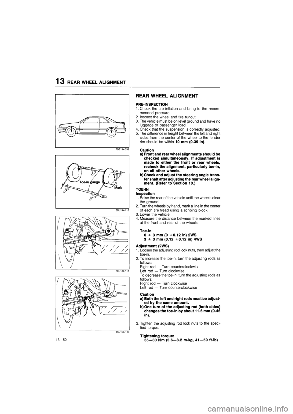
TOE-IN
Inspection
1. Raise the rear of the vehicle until the wheels clear
the ground.
2. Turn the wheels by hand, mark a line in the center
of each tire tread using a scribing block.
3. Lower the vehicle.
4. Measure the distance between the marked lines
at the front and rear of the wheels.
Toe-in
0 ± 3 mm (0 ±0.12 in) 2WS
3 ± 3 mm (0.12 ±0.12 in) 4WS
Adjustment (2WS)
1. Loosen the adjusting rod lock nuts, then adjust the
toe-in.
2. To increase the toe-in, turn the adjusting rods as
follows:
Right rod — Turn counterclockwise
Left rod — Turn clockwise
To decrease the toe-in, turn the adjusting rods as
follows:
Right rod — Turn clockwise
Left rod — Turn counterclockwise
Caution
a) Both the left and right rods must be adjust-
ed by the same amount.
b) One turn of the adjusting rod (both sides)
changes the toe-in by about 11.6 mm (0.46
in).
3. Tighten the adjusting rod lock nuts to the speci-
fied torque.
Tightening torque:
55—80 N-m (5.6—8.2 m-kg, 41—59 ft-lb)
Page 1551 of 1865
13 REAR WHEEL ALIGNMENT
2. Measure the camber angle with the caster/cam-
ber gauge.
Camber: -0°30' ± 45' (2WS)
0°00' ± 45' (4WS)
86U13X-123
Front
EAR TURNING ANGLE (4WS)
Place the rear wheels on a turning radius gauge.
Jack up the front of the vehicle.
Start the engine and let it idle.
Caution
If the engine is stopped while the steering
wheel is left turned to one side or the other,
the rear wheels will return to the straight-
ahead direction, and, when the engine is later
started once again, the direction of the rear
wheels will change. Be sure, therefore, to
check to be sure that the wheels are not
touching, or close to, anyone's hands or feet,
or any other object, when the engine is
stopped or started.
Turn the steering wheel fully left and right, and
measure the rear turning angle.
Rear turning angle Inner 5°00' ± 45'
Outer 5°00' ± 45'
If not within specification, adjust the rear turning
angle. (Refer to Section 10)
86U13X-125
13—54
Page 1624 of 1865
INSTRUMENT PANEL 1 4
INSTRUMENT PANEL
STRUCTURAL VIEW
1. Rear console
2. Upper plate.
3. Front console
4. Glove compartment
5. Side cover
6. Side cover
7. Box
8. Ashtray
9. Center panel
10. Heater control assembly
11. Steering wheel cap
12. Steering wheel
13. Column cover
14. Switch panel
76G14X-036
15. Cap
16. Meter hood
17. Duct
18. Duct and under cover
19. Under cover
20. Duct
21. Meter assembly
22. Instrument panel
14—73
Page 1627 of 1865
1 4 INSTRUMENT PANEL
6. Remove the steering wheel cap.
76G14X-026
7. Remove the steering wheel mounting nut.
76G14X-027
9. Remove the screws and remove the column covers
(upper and lower).
76G14X-028
14—76
Page 1630 of 1865
INSTRUMENT PANEL 1 4
27. Remove the instrument panel side mounting bolts.
86U14X-191
28. Remove the instrument panel center bracket
mounting bolts.
86U14X-192
29. Remove the steering shaft mounting bolts.
86U14X-193
30. Disconnect the dash harness connectors.
31. Remove the instrument panel.
86U14X-194
14—79
Page 1631 of 1865

14 INSTRUMENT PANEL
INSTALLATION
Install in the reverse order of removal, noting the fol-
lowing.
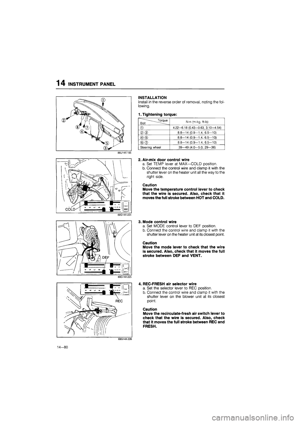
1. Tightening torque:
.^Torque Bolt
N-m (m-kg,
ft-lb)
©
4.22-6.18 (0.43-0.63, 3.10-4.54)
®(D
8.8-14 (0.9—1.4, 6.5—10)
©(D
8.8—14 (0.9—1.4, 6.5—10)
©@
8.8-14 (0.9-1.4, 6.5-10)
Steering wheel 39-49 (4.0—5.0, 29—36)
86U14X-195
2. Air-mix door control wire
a. Set TEMP lever at MAX—COLD position.
b. Connect the control wire and clamp it with the
shutter lever on the heater unit all the way to the
right side.
Caution
Move the temperature control lever to check
that the wire is secured. Also, check that it
moves the full stroke between HOT and COLD.
69G14X-224
3. Mode control wire
a. Set MODE control lever to DEF position.
b. Connect the control wire and clamp it with the
shutter lever on the heater unit at its closest point.
Caution
Move the mode lever to check that the wire
is secured. Also, check that it moves the full
stroke between DEF and VENT.
69G14X-225
, REC-FRESH air selector wire
a. Set the selector lever to REC position.
b. Connect the control wire and clamp it with the
shutter lever on the blower unit at its closest
point.
Caution
Move the recirculate-fresh air switch lever to
check that the wire is secured. Also, check
that it moves the full stroke between REC and
FRESH.
69G14X-226
14—80
Page 1654 of 1865
A: Frame mounting nut (M10)
B: Front fender panel mounting nut (M6)
C: Crossmember mounting bolt (M12)
D: Front mounting block
E: Steering bracket mounting nut (M12)
F: Front fender panel mounting nut (M6)
G: Frame mounting bolt (M12)
H: Front frame, lower standard hole (8)
I : Front frame [c], lower standard hole (12)
J : Crossmember mounting nut (M10)
(Crossmember mounting bolt (M10)...4WS)
K: Rear mounting block
L : Crossmember mounting nut (M10)
(Crossmember mounting bolt (M12)...4WS)
M: Rear frame, lower standard hole(10<£)
N: Rear bumper mounting hole (140)
l (outside, lower)
86U14X-193
Page 1667 of 1865
1 5 COMBINATION SWITCH
CONBINATION SWITCH
STRUCTURAL VIEW
Left hand drive
Alignment mark
Right hand drive
Alignment mark
76G15X-002
1. Light and turn signal switch lever
2. Windshield wiper and washer switch lever
3. Cruise control switch
4. Steering angle sensor
5. Hazard switch
6. Light switch connectors
7. Turn signal switch connector
8. Windshield wiper and washer switch con-
nector
9. Steering angle sensor connector
10. Turn signal and hazard switch connector
15—12