1987 MAZDA 626 suspension
[x] Cancel search: suspensionPage 1498 of 1865
13
SUSPENSION
OUTLINE 13— 2
STRUCTURAL VIEW 13— 2
SPECIFICATIONS 13— 4
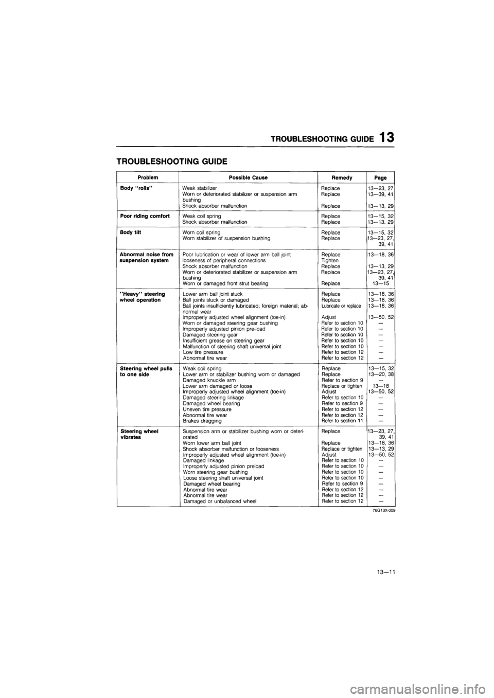
TROUBLESHOOTING GUIDE 13—11
FRONT SHOCK ABSORBER AND
SPRING 13—13
REMOVAL AND INSTALLATION 13—13
DISASSEMBLY AND ASSEMBLY 13—15
FRONT LOWER ARM 13—18
REMOVAL AND INSTALLATION 13—18
FRONT STABILIZER (4WS) 13—23
REMOVAL AND INSTALLATION 13—23
FRONT STABILIZER 13—27
REMOVAL AND INSTALLATION 13—27
REAR SHOCK ABSORBER AND SPRING .. 13—29
REMOVAL AND INSTALLATION 13—29
DISASSEMBLY AND ASSEMBLY 13—32
LATERAL LINK AND TRAILING LINK 13—34
REMOVAL AND INSTALLATION 13—34
REAR LOWER ARM AND TRAILING
LINK (4WS) 13—36
REMOVAL AND INSTALLATION 13—36
REAR STABILIZER 13—39
REMOVAL AND INSTALLATION 13—39
REAR STABILIZER AND CONTROL
LINK (4WS) 13—41
REMOVAL AND INSTALLATION 13—41
REAR CROSSMEMBER (4WS) 13—44
REMOVAL AND INSTALLATION 13—44
FRONT WHEEL ALIGNMENT 13—50
REAR WHEEL ALIGNMENT 13—52
76G13X-001
Page 1499 of 1865
13 OUTLINE
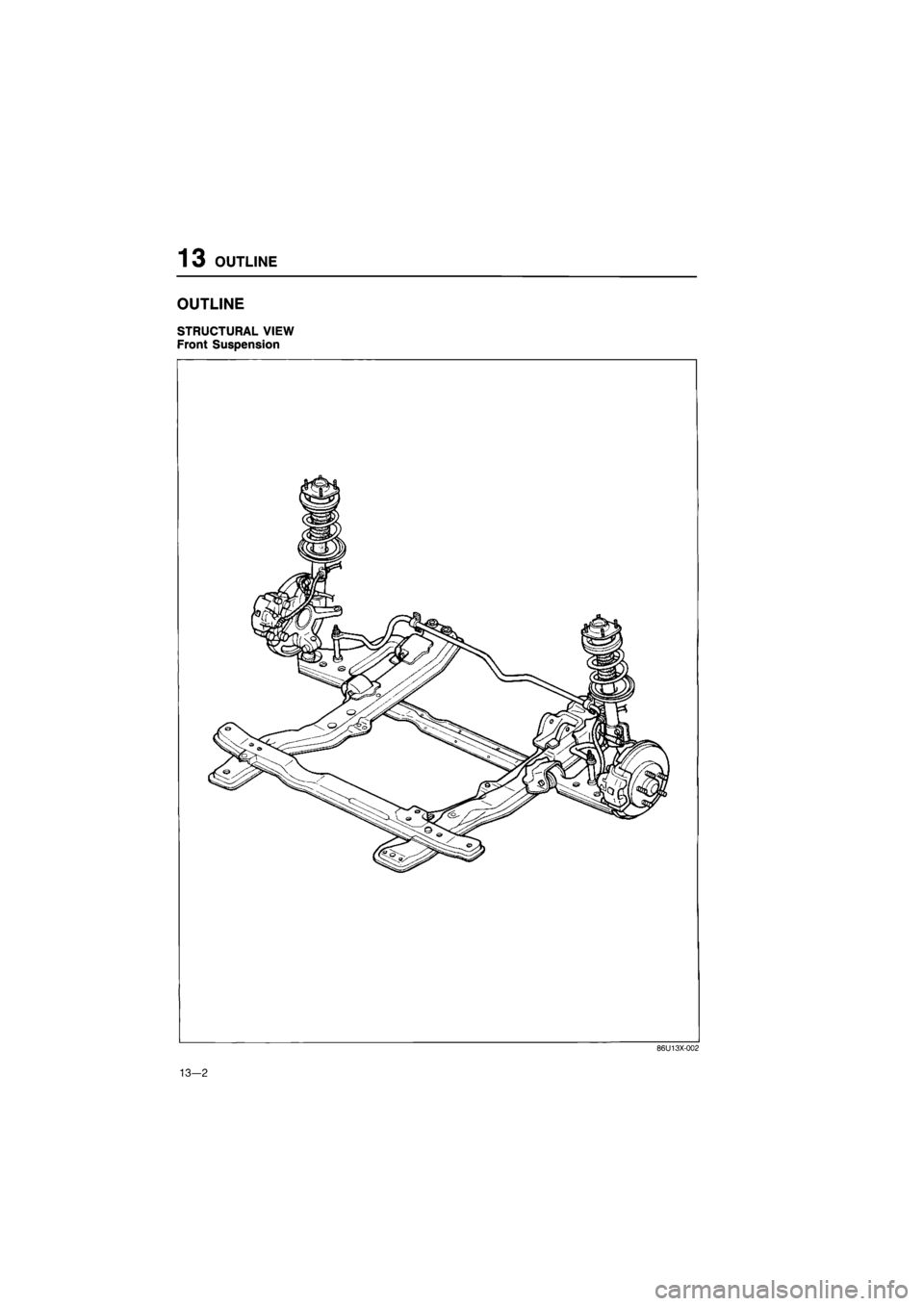
OUTLINE
STRUCTURAL VIEW
Front Suspension
86U13X-002
13—2
Page 1500 of 1865
OUTLINE 13
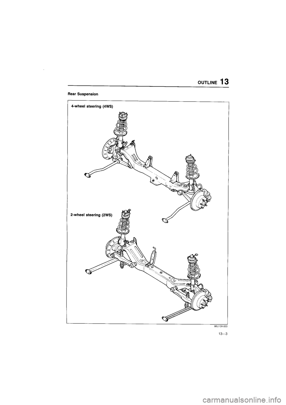
Rear Suspension
4-wheel steering (4WS)
86U13X-003
13—3
Page 1501 of 1865
13 OUTLINE
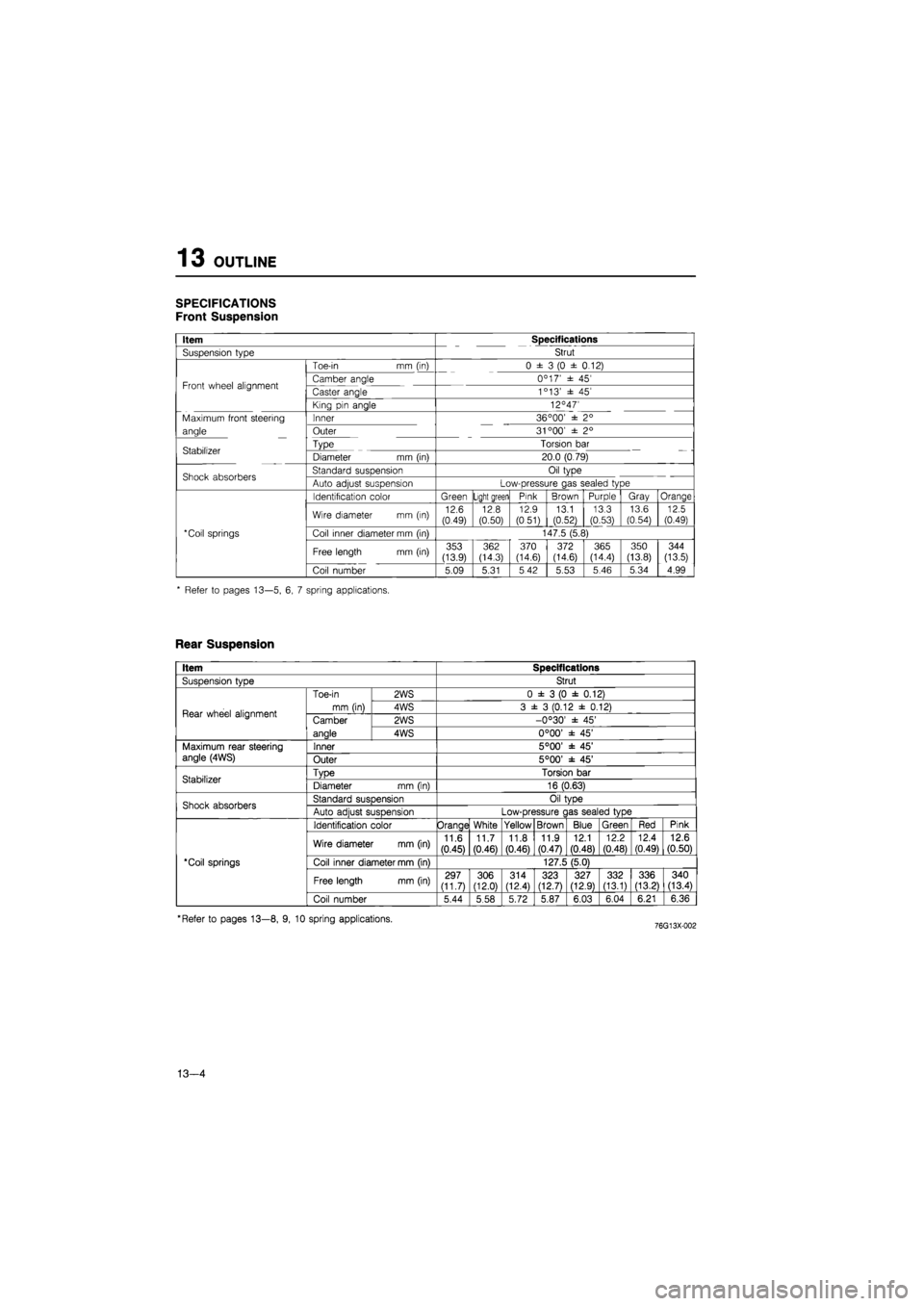
SPECIFICATIONS
Front Suspension
Item Specifications
Suspension type Strut
Toe-in mm (in) 0 ± 3 (0 ± 0.12)
Front wheel alignment Camber angle 0C 17' ± 45' Front wheel alignment Caster angle 1c 13' ± 45'
King pin angle 12°47'
Maximum front steering Inner 36 °00' ± 2°
angle Outer 31 °00' ± 2°
Stabilizer Type Torsion bar Stabilizer Diameter mm (in) 20.0 (0.79)
Shock absorbers Standard suspension Oil type Shock absorbers Auto adjust suspension Low-pressure gas sealed type
Identification color Green Light green Pink Brown Purple Gray Orange
Wire diameter mm (in) 12.6 (0.49) 12.8 (0.50)
12.9
(0.51) 13.1 (0.52)
13.3 (0.53)
13.6
(0.54) 12.5 (0.49)
*Coil springs Coil inner diameter mm (in) 147.5 (5.8)
Free length mm (in) 353 (13.9)
362 (14.3) 370 (14.6) 372 (14.6) 365 (14.4)
350
(13.8)
344
(13.5)
Coil number 5.09 5.31 5 42 5.53 5.46 5.34 4.99
* Refer to pages 13—5, 6, 7 spring applications.
Rear Suspension
Item Specifications
SusDension tvDe Strut
Rear wheel alignment
Toe-in
mm (in)
2WS 0 ± 3 (0 ± 0.12)
Rear wheel alignment
Toe-in
mm (in) 4WS 3 ± 3 (0.12 ± 0.12) Rear wheel alignment Camber
anale
2WS -0°30' ± 45' Rear wheel alignment Camber
anale 4WS 0°00' ± 45'
Maximum rear steering angle (4WS) Inner 5°00' ± 45' Maximum rear steering angle (4WS) Outer 5°00' ± 45'
Stabilizer TvDe Torsion bar Stabilizer Diameter mm (in) 16 (0.63)
Shock absorbers Standard susDension Oil tvDe Shock absorbers Auto adiust suspension Low-pressure c las sealed type
'Coil springs
Identification color Orange White Yellow Brown Blue Green Red Pink
'Coil springs
Wire diameter mm (in) 11.6
(0.45)
11.7 (0.46) 11.8
(0.46)
11.9 (0.47)
12.1
(0.48)
12.2
(0.48)
12.4 (0.49) 12.6 (0.50)
'Coil springs Coil inner diameter mm (in) 127.5 (5.0) 'Coil springs
Free length mm (in) 297 (11.7) 306 (12.0)
314 (12.4) 323 (12.7) 327 (12.9) 332 (13.1) 336 (13.21 340 (13.4)
'Coil springs
Coil number 5.44 5.58 5.72 5.87 6.03 6.04 6.21 6.36
'Refer to pages 13—8, 9, 10 spring applications.
13—4
Page 1508 of 1865
TROUBLESHOOTING GUIDE 1 3
TROUBLESHOOTING GUIDE
Problem Possible Cause Remedy Page
Body "rolls" Weak stabilizer Replace 13-23, 27 Worn or deteriorated stabilizer or suspension arm Replace 13—39, 41 bushing
Shock absorber malfunction Replace 13-13, 29
Poor riding comfort Weak coil spring Replace 13-15, 32 Shock absorber malfunction Replace 13-13. 29
Body tilt Worn coil spring Replace 13-15, 32 Worn stabilizer of suspension bushing Replace 13-23, 27,
39, 41
Abnormal noise from Poor lubrication or wear of lower arm ball joint Replace 13-18, 36 suspension system looseness of peripheral connections Tighten
Shock absorber malfunction Replace 13-13, 29 Worn or deteriorated stabilizer or suspension arm Replace 13—23, 27, bushing 39, 41 Worn or damaged front strut bearing Replace 13-15
"Heavy" steering Lower arm ball joint stuck Replace 13—18, 36
wheel operation Ball joints stuck or damaged Replace 13-18, 36
Ball joints insufficiently lubricated; foreign material; ab-Lubricate or replace 13-18, 36
normal wear Improperly adjusted wheel alignment (toe-in) Adjust 13-50, 52
Worn or damaged steering gear bushing Refer to section 10 —
Improperly adjusted pinion pre-load Refer to section 10 —
Damaged steering gear Refer to section 10 —
Insufficient grease on steering gear Refer to section 10 —
Malfunction of steering shaft universal joint Refer to section 10 —
Low tire pressure Refer to section 12 —
Abnormal tire wear Refer to section 12 —
Steering wheel pulls Weak coil spring Replace 13-15, 32
to one side Lower arm or stabilizer bushing worn or damaged Replace 13-20, 38
Damaged knuckle arm Refer to section 9 —
Lower arm damaged or loose Replace or tighten 13-18 Improperly adjusted wheel alignment (toe-in) Adjust 13-50, 52
Damaged steering linkage Refer to section 10 —
Damaged wheel bearing Refer to section 9 —
Uneven tire pressure Refer to section 12 —
Abnormal tire wear Refer to section 12 —
Brakes dragging Refer to section 11 —
Steering wheel Suspension arm or stabilizer bushing worn or deteri-Replace 13—23, 27.
vibrates orated 39, 41
Worn lower arm ball joint Replace 13-18, 36
Shock absorber malfunction or looseness Replace or tighten 13-13, 29
Improperly adjusted wheel alignment (toe-in) Adjust 13-50, 52 Damaged linkage Refer to section 10
Improperly adjusted pinion preload Refer to section 10
Worn steering gear bushing Refer to section 10 —
Loose steering shaft universal joint Refer to section 10 —
Damaged wheel bearing Refer to section 9 —
Abnormal tire wear Refer to section 12 —
Abnormal tire wear Refer to section 12 —
Damaged or unbalanced wheel Refer to section 12 —
76G13X-009
13—11
Page 1511 of 1865
1 3 FRONT SHOCK ABSORBER AND SPRING
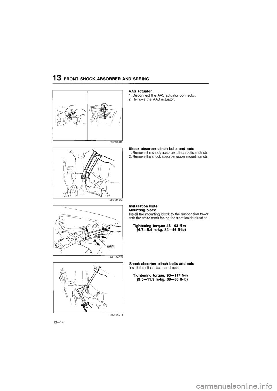
AAS actuator
1. Disconnect the AAS actuator connector.
2. Remove the AAS actuator.
86U13X-011
Shock absorber clinch bolts and nuts
1. Remove the shock absorber clinch bolts and nuts.
2. Remove the shock absorber upper mounting nuts.
76G13X-013
Installation Note
Mounting block
Install the mounting block to the suspension tower
with the white mark facing the front-inside direction.
Tightening torque: 46—63 N-m
(4.7—6.4 m-kg, 34—46 ft-lb)
86U13X-013
Shock absorber clinch bolts and nuts
Install the clinch bolts and nuts.
Tightening torque: 93—117
N
m
(9.5—11.9 m-kg, 69—86 ft-lb)
86U13X-014
13—14
Page 1549 of 1865
13 REAR WHEEL ALIGNMENT
76G13X-033
86U13X-116
86U13X-117
86U13X-116
13-52
REAR WHEEL ALIGNMENT
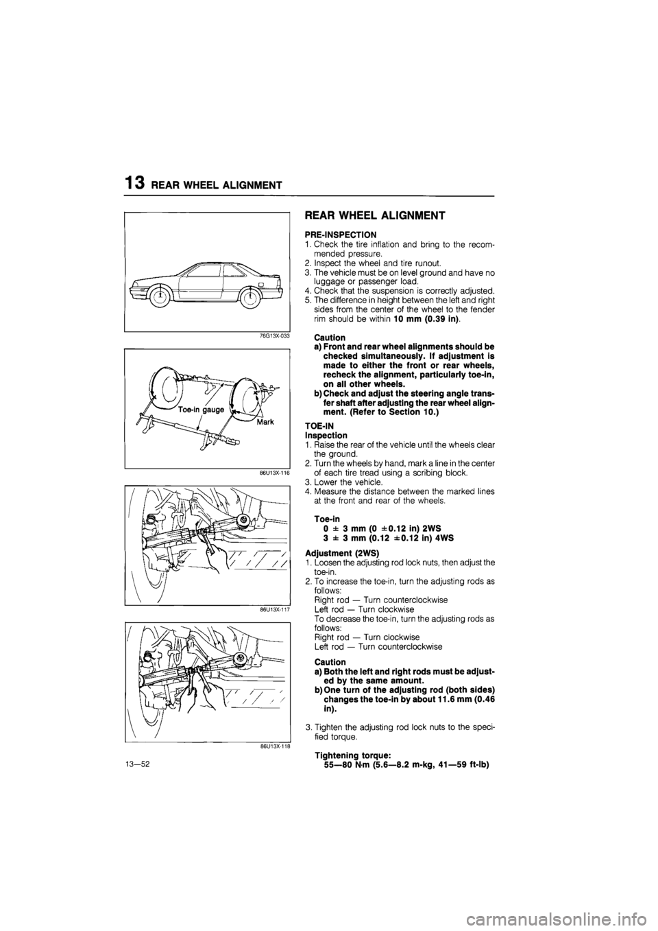
PRE-INSPECTION
1. Check the tire inflation and bring to the recom-
mended pressure.
2. Inspect the wheel and tire runout.
3. The vehicle must be on level ground and have no
luggage or passenger load.
4. Check that the suspension is correctly adjusted.
5. The difference in height between the left and right
sides from the center of the wheel to the fender
rim should be within 10 mm (0.39 in).
Caution
a) Front and rear wheel alignments should be
checked simultaneously. If adjustment is
made to either the front or rear wheels,
recheck the alignment, particularly toe-in,
on all other wheels.
b) Check and adjust the steering angle trans-
fer shaft after adjusting the rear wheel align-
ment. (Refer to Section 10.)
TOE-IN
Inspection
1. Raise the rear of the vehicle until the wheels clear
the ground.
2. Turn the wheels by hand, mark a line in the center
of each tire tread using a scribing block.
3. Lower the vehicle.
4. Measure the distance between the marked lines
at the front and rear of the wheels.
Toe-in
0 ± 3 mm (0 ±0.12 in) 2WS
3 ± 3 mm (0.12 ±0.12 in) 4WS
Adjustment (2WS)
1. Loosen the adjusting rod lock nuts, then adjust the
toe-in.
2. To increase the toe-in, turn the adjusting rods as
follows:
Right rod — Turn counterclockwise
Left rod — Turn clockwise
To decrease the toe-in, turn the adjusting rods as
follows:
Right rod — Turn clockwise
Left rod — Turn counterclockwise
Caution
a) Both the left and right rods must be adjust-
ed by the same amount.
b) One turn of the adjusting rod (both sides)
changes the toe-in by about 11.6 mm (0.46
in).
3. Tighten the adjusting rod lock nuts to the speci-
fied torque.
Tightening torque:
55—80 N-m (5.6—8.2 m-kg, 41—59 ft-lb)
Page 1656 of 1865
15
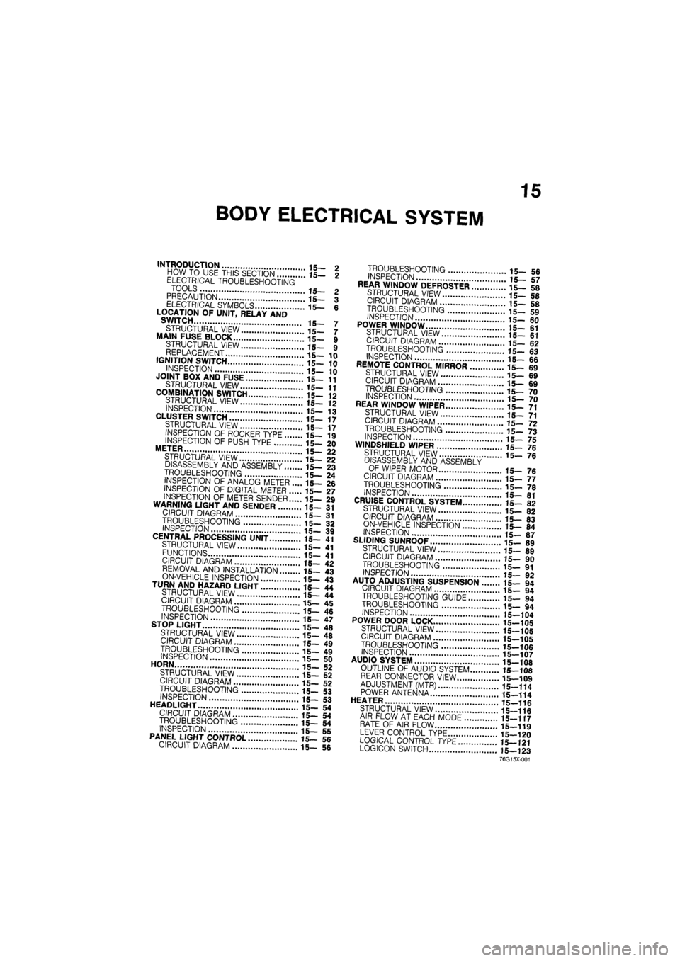
BODY ELECTRICAL SYSTEM
INTRODUCTION 15- 2 HOW TO USE THIS SECTION 15— 2 ELECTRICAL TROUBLESHOOTING TOOLS 15- 2 PRECAUTION 15— 3 ELECTRICAL SYMBOLS 15- 6 LOCATION OF UNIT, RELAY AND SWITCH 15- 7
STRUCTURAL VIEW 15— 7 MAIN FUSE BLOCK 15- 9 STRUCTURAL VIEW 15— 9 REPLACEMENT 15—10 IGNITION SWITCH 15—10
INSPECTION 15— 10 JOINT BOX AND FUSE 15—11
STRUCTURAL VIEW 15—11
COMBINATION SWITCH 15-12 STRUCTURAL VIEW 15- 12 INSPECTION 15— 13 CLUSTER SWITCH 15—17 STRUCTURAL VIEW 15— 17 INSPECTION OF ROCKER TYPE 15— 19
INSPECTION OF PUSH TYPE 15— 20 METER 15— 22 STRUCTURAL VIEW 15— 22 DISASSEMBLY AND ASSEMBLY 15— 23
TROUBLESHOOTING 15— 24 INSPECTION OF ANALOG METER .... 15— 26 INSPECTION OF DIGITAL METER 15— 27
INSPECTION OF METER SENDER 15— 29 WARNING LIGHT AND SENDER 15- 31 CIRCUIT DIAGRAM 15— 31
TROUBLESHOOTING 15- 32 INSPECTION 15— 39 CENTRAL PROCESSING UNIT 15— 41 STRUCTURAL VIEW 15— 41 FUNCTIONS 15- 41 CIRCUIT DIAGRAM 15— 42 REMOVAL AND INSTALLATION 15— 43
ON-VEHICLE INSPECTION 15- 43 TURN AND HAZARD LIGHT 15- 44 STRUCTURAL VIEW 15— 44 CIRCUIT DIAGRAM 15— 45
TROUBLESHOOTING 15- 46 INSPECTION 15— 47 STOP LIGHT 15— 48
STRUCTURAL VIEW 15— 48 CIRCUIT DIAGRAM 15— 49
TROUBLESHOOTING 15- 49 INSPECTION 15- 50 HORN 15— 52 STRUCTURAL VIEW 15— 52 CIRCUIT DIAGRAM 15— 52 TROUBLESHOOTING 15— 53 INSPECTION 15-53 HEADLIGHT 15— 54 CIRCUIT DIAGRAM 15— 54 TROUBLESHOOTING 15— 54 INSPECTION 15— 55 PANEL LIGHT CONTROL 15— 56 CIRCUIT DIAGRAM 15— 56
TROUBLESHOOTING 15_ 5fi INSPECTION 17 REAR WINDOW DEFROSTER ..i".'! 15- 58
STRUCTURAL VIEW 15-5fl CIRCUIT DIAGRAM 15_ «
TROUBLESHOOTING '.. 15_ 59
INSPECTION
15-60 POWER WINDOW 15-61 STRUCTURAL VIEW il_ «1 CIRCUIT DIAGRAM 15_ 62 TROUBLESHOOTING 15- «3 INSPECTION 15-66 REMOTE CONTROL MIRROR ........15- 69 STRUCTURAL VIEW 15-69 CIRCUIT DIAGRAM 15_ 69
TROUBLESHOOTING 15_ 70 INSPECTION 15_ 70 REAR WINDOW WIPER 15_ 71 STRUCTURAL VIEW 15-71 CIRCUIT DIAGRAM .'.'.'...' 15_ 72
TROUBLESHOOTING 15-73 INSPECTION 15-75 WINDSHIELD WIPER 15-76 STRUCTURAL VIEW ' ' 15— 7e
DISASSEMBLY AND ASSEMBLY OF WIPER MOTOR 15_ 76 CIRCUIT DIAGRAM 15-77 TROUBLESHOOTING " " 15— 70 INSPECTION 15-81 CRUISE CONTROL SYSTEM 15- 82 STRUCTURAL VIEW 15-82 CIRCUIT DIAGRAM 15-83 ON-VEHICLE INSPECTION \..\m 15- 84 INSPECTION 15-87 SLIDING SUNROOF 15-89 STRUCTURAL VIEW 15_ 89 CIRCUIT DIAGRAM i5_ 90
TROUBLESHOOTING 15— 91 INSPECTION 15_ 90 AUTO ADJUSTING SUSPENSION 15— 94
CIRCUIT DIAGRAM 15- 94
TROUBLESHOOTING GUIDE 15— 94
TROUBLESHOOTING 15— 94
INSPECTION 15-104
POWER DOOR LOCK 15-105
STRUCTURAL VIEW 15-105
CIRCUIT DIAGRAM 15-105
TROUBLESHOOTING 15-106 INSPECTION 15-107 AUDIO SYSTEM " 15_108 OUTLINE OF AUDIO SYSTEM 15-108 REAR CONNECTOR VIEW 15-109 ADJUSTMENT (MTR) 15—114 POWER ANTENNA 15-114 HEATER J
STRUCTURAL VIEW 15-116 AIR FLOW AT EACH MODE 15-117 RATE OF AIR FLOW 15-119 LEVER CONTROL TYPE 15-120 LOGICAL CONTROL
TYPE
15—121 LOGICON SWITCH 15—123
76G15X-001