1987 MAZDA 626 suspension
[x] Cancel search: suspensionPage 1749 of 1865
1 5 AUTO ADJUSTING SUSPENSION (AAS)
AUTO ADJUSTING SUSPENSION (AAS)
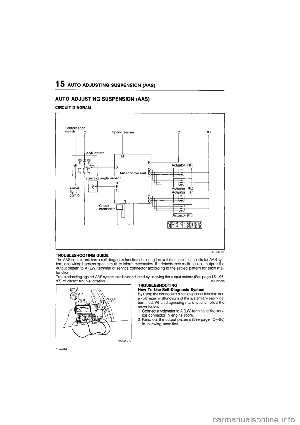
CIRCUIT DIAGRAM
Combination switch iq Speed sensor
M
Panel light
control
AAS control unit
Steering angle sensor
H
N
Check connector
IG IG
Actuator (RR)
-P-Sl
-t-^J
—Pwsl
Actuator (RL)
Actuator (FR) P5fl
+
Actuator (FL)
QO M K GIE C A
ft N J HI F D B
86U15X-151
TROUBLESHOOTING GUIDE
The AAS control unit has a self-diagnosis function detecting the unit itself, electrical parts for AAS sys-
tem, and wiring harness open circuit, to inform mechanics. If it detects their malfunctions, outputs the
output pattern to A (LW) terminal of service connector according to the settled pattern for each mal-
function.
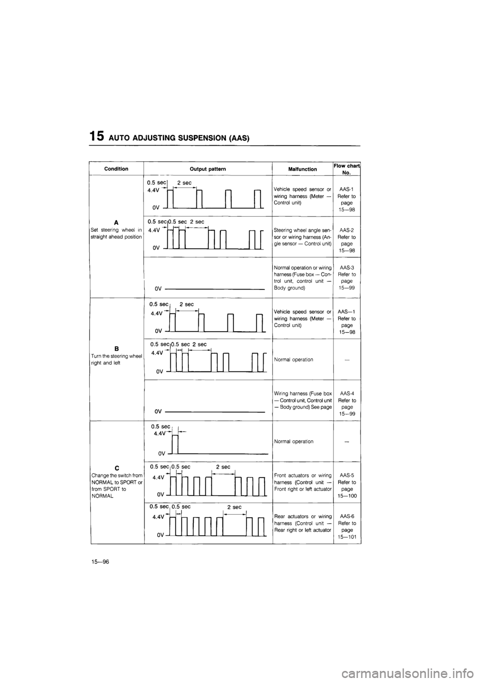
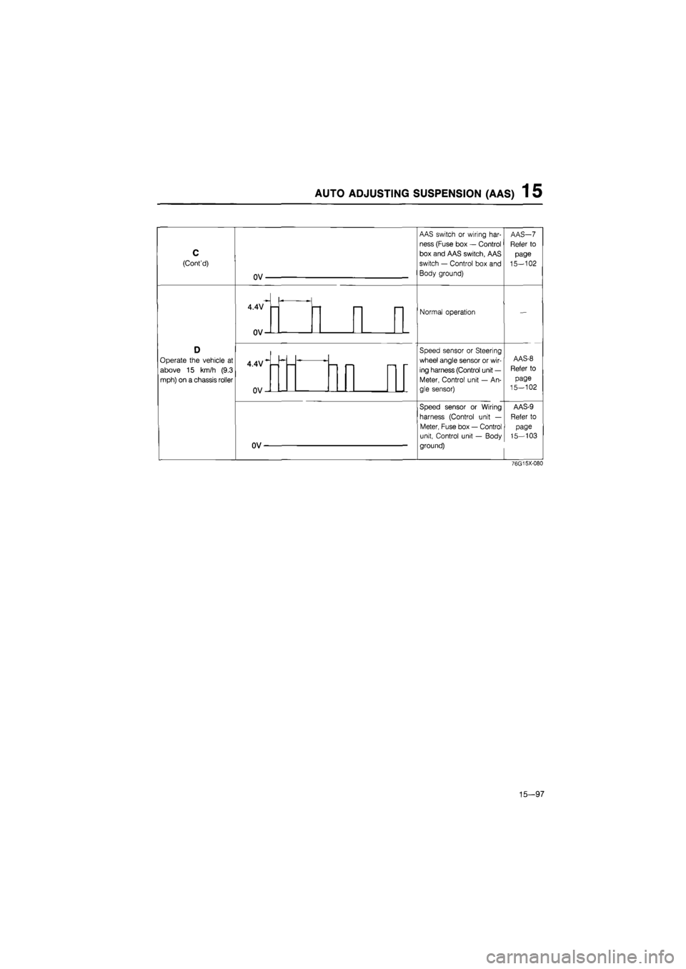
Troubleshooting against AAS system can be conducted by knowing the output pattern (See page 15—96,
97) to detect trouble location. 76gisx-o2o
TROUBLESHOOTING
How To Use Self-Diagnosis System
By using the control unit's self-diagnosis function and
a voltmeter, malfunctions of the system are easily de-
termined. When diagnosing malfunctions, follow the
steps bellow.
1. Connect a voltmeter to A (LW) terminal of the serv-
ice connector in engine room.
2. Read out the output patterns (See page 15—96)
in following condition.
76G15X-079
15—94
Page 1750 of 1865
AUTO ADJUSTING SUSPENSION (AAS) 1 5
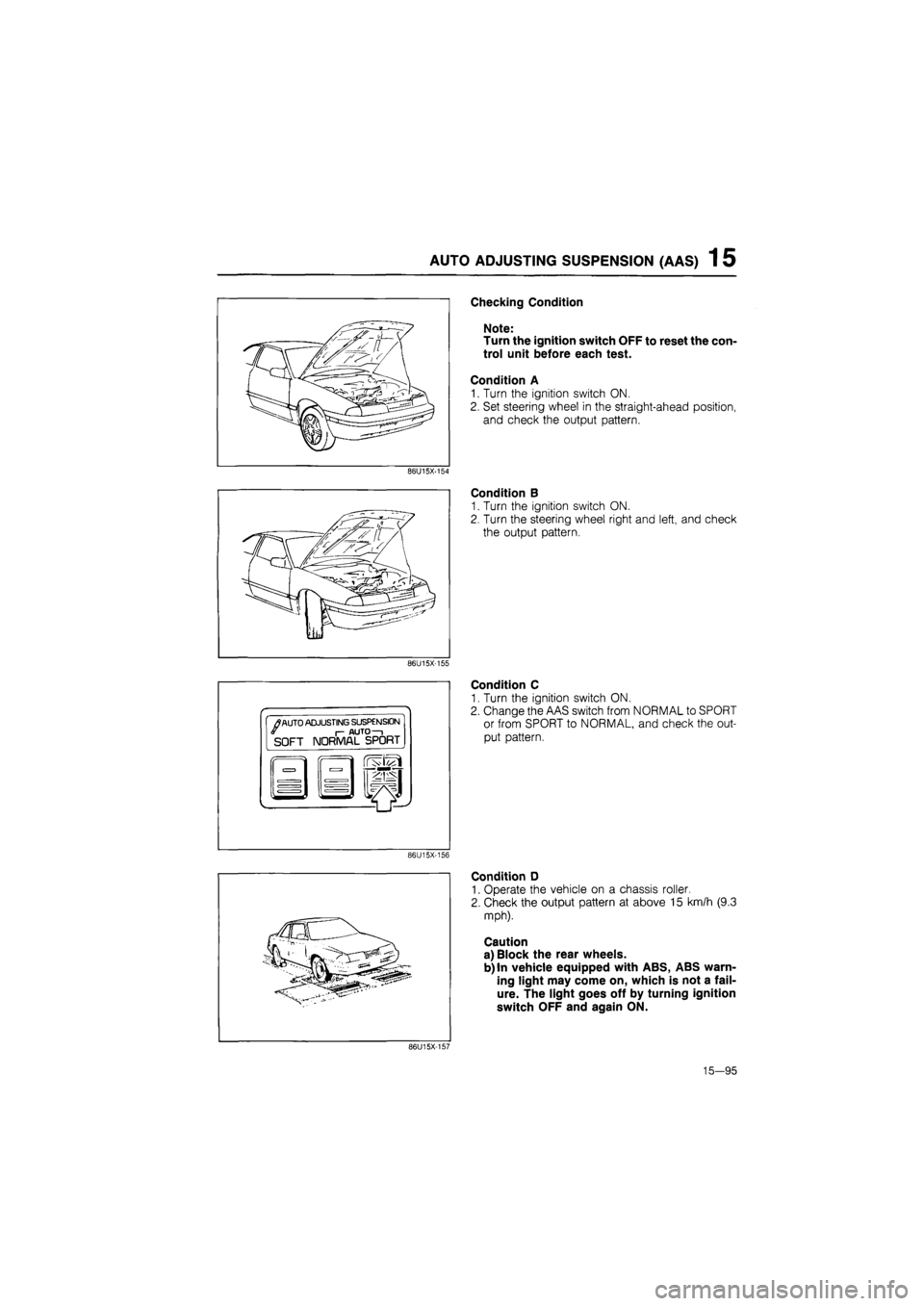
Checking Condition
Note:
Turn the ignition switch OFF to reset the con-
trol unit before each test.
Condition A
1. Turn the ignition switch ON.
2. Set steering wheel in the straight-ahead position,
and check the output pattern.
86U15X-154
Condition B
1. Turn the ignition switch ON.
2. Turn the steering wheel right and left, and check
the output pattern.
86U15X-155
•
/
AUTO ADJUSTING SUSPENSION I- AUTO—i SOFT NORMAL SPORT
Condition C
1. Turn the ignition switch ON.
2. Change the AAS switch from NORMAL to SPORT
or from SPORT to NORMAL, and check the out-
put pattern.
86U15X-156
Condition D
1. Operate the vehicle on a chassis roller.
2. Check the output pattern at above 15 km/h (9.3
mph).
Caution
a) Block the rear wheels.
b) In vehicle equipped with ABS, ABS warn-
ing light may come on, which is not a fail-
ure. The light goes off by turning ignition
switch OFF and again ON.
86U15X-157
15—95
Page 1751 of 1865
1 5 AUTO ADJUSTING SUSPENSION (AAS)
Condition Output pattern Malfunction Flow chart
No.
A
Set steering wheel
in
straight ahead position
0.5 sec
4.4V
n\/
2 sec
Vehicle speed sensor
or
wiring harness (Meter
—
Control unit)
AAS-1
Refer
to
page
15—98
A
Set steering wheel
in
straight ahead position
Vehicle speed sensor
or
wiring harness (Meter
—
Control unit)
AAS-1
Refer
to
page
15—98
A
Set steering wheel
in
straight ahead position
0.5 secO.!
4.4V
nv
i sec
2
sec
— <—i i— -
Steering wheel angle sen-
sor
or
wiring harness (An-
gle sensor
—
Control unit)
AAS-2
Refer
to
page
15-98
A
Set steering wheel
in
straight ahead position
-
Steering wheel angle sen-
sor
or
wiring harness (An-
gle sensor
—
Control unit)
AAS-2
Refer
to
page
15-98
A
Set steering wheel
in
straight ahead position
nv
Normal operation or wiring
harness (Fuse box
—
Con-
trol unit, control unit
—
Body ground)
AAS-3
Refer
to
page
15-99
A
Set steering wheel
in
straight ahead position
Normal operation or wiring
harness (Fuse box
—
Con-
trol unit, control unit
—
Body ground)
AAS-3
Refer
to
page
15-99
B
Turn the steering wheel
right and left
0.5 sec
4.4V
n\/
2 sec
—
Vehicle speed sensor
or
wiring harness (Meter
—
Control unit)
AAS-1
Refer
to
page
15-98
B
Turn the steering wheel
right and left
Vehicle speed sensor
or
wiring harness (Meter
—
Control unit)
AAS-1
Refer
to
page
15-98
B
Turn the steering wheel
right and left
0.5 sec 0
4.4V""-
.5 se c 2 se
-
Normal operation
—
B
Turn the steering wheel
right and left Normal operation
—
B
Turn the steering wheel
right and left
ov
Wiring harness (Fuse box
— Control unit, Control unit
— Body ground) See page
AAS-4
Refer
to
page
15—99
B
Turn the steering wheel
right and left
Wiring harness (Fuse box
— Control unit, Control unit
— Body ground) See page
AAS-4
Refer
to
page
15—99
C
Change the switch from
NORMAL to SPORT
or
from SPORT
to
NORMAL
0.5 sec
4.4V-""
_
n
Normal operation
—
C
Change the switch from
NORMAL to SPORT
or
from SPORT
to
NORMAL
Normal operation
—
C
Change the switch from
NORMAL to SPORT
or
from SPORT
to
NORMAL
0.5 sec 0
4.4V
nv
.5 se c
—
2 se
C
i—1 i—i
Front actuators
or
wiring
harness (Control unit
—
Front right
or
left actuator
AAS-5
Refer
to
page
15-100
C
Change the switch from
NORMAL to SPORT
or
from SPORT
to
NORMAL
Front actuators
or
wiring
harness (Control unit
—
Front right
or
left actuator
AAS-5
Refer
to
page
15-100
C
Change the switch from
NORMAL to SPORT
or
from SPORT
to
NORMAL
0.5 sec 0
4.4V*-
n\/
.5 se c
— r— —
2 sec
—1
Rear actuators
or
wiring
harness (Control unit
—
Rear right
or
left actuator
AAS-6
Refer
to
page
15-101
C
Change the switch from
NORMAL to SPORT
or
from SPORT
to
NORMAL
Rear actuators
or
wiring
harness (Control unit
—
Rear right
or
left actuator
AAS-6
Refer
to
page
15-101
15-96
Page 1752 of 1865
AUTO ADJUSTING SUSPENSION (AAS) 1 5
C
(Cont'd)
Operate
the
vehicle
at
above
15 km/h (9.3
mph) on
a
chassis roller
OV-
4.4V
0V-
4.4V
OV-
OV
AAS switch
or
wiring har-
ness (Fuse box
—
Control
box and AAS switch, AAS
switch
—
Control box and
Body ground)
Normal operation
Speed sensor
or
Steering
wheel angle sensor
or
wir-
ing harness (Control unit
—
Meter, Control unit
—
An-
gle sensor)
Speed sensor
or
Wiring
harness (Control unit
—
Meter, Fuse box
—
Control
unit, Control unit
—
Body
ground)
76G15X-080
15-97
Page 1753 of 1865
1 5 AUTO ADJUSTING SUSPENSION
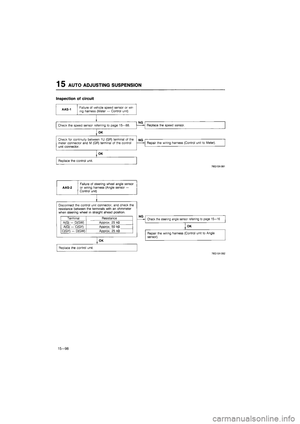
Inspection of circuit
OK
Check
for
continuity between
1U
(GR) terminal
of
the meter connector and
M
(GR) terminal
of
the control unit connector.
Repair the wiring harness (Control unit
to
Meter).
OK
Replace the control unit.
76G15X-081
AAS-2
Failure
of
steering wheel angle sensor
or wiring harness (Angle sensor
—
Control unit)
I
Disconnect the control unit connector, and check
the
resistance between the terminals with
an
ohmmeter
when steering wheel
in
straight ahead position.
Terminal Resistance
A(G)
-
D(GW) ADDrox.
25 kfi
A(G)
-
C(GY) Approx.
50 kfl
C(GY^
-
D(G\M ADorox.
25 kfi
OK
Replace the control unit.
76G15X-082
15-98
Page 1754 of 1865
AUTO ADJUSTING SUSPENSION
(AAS) 1 5
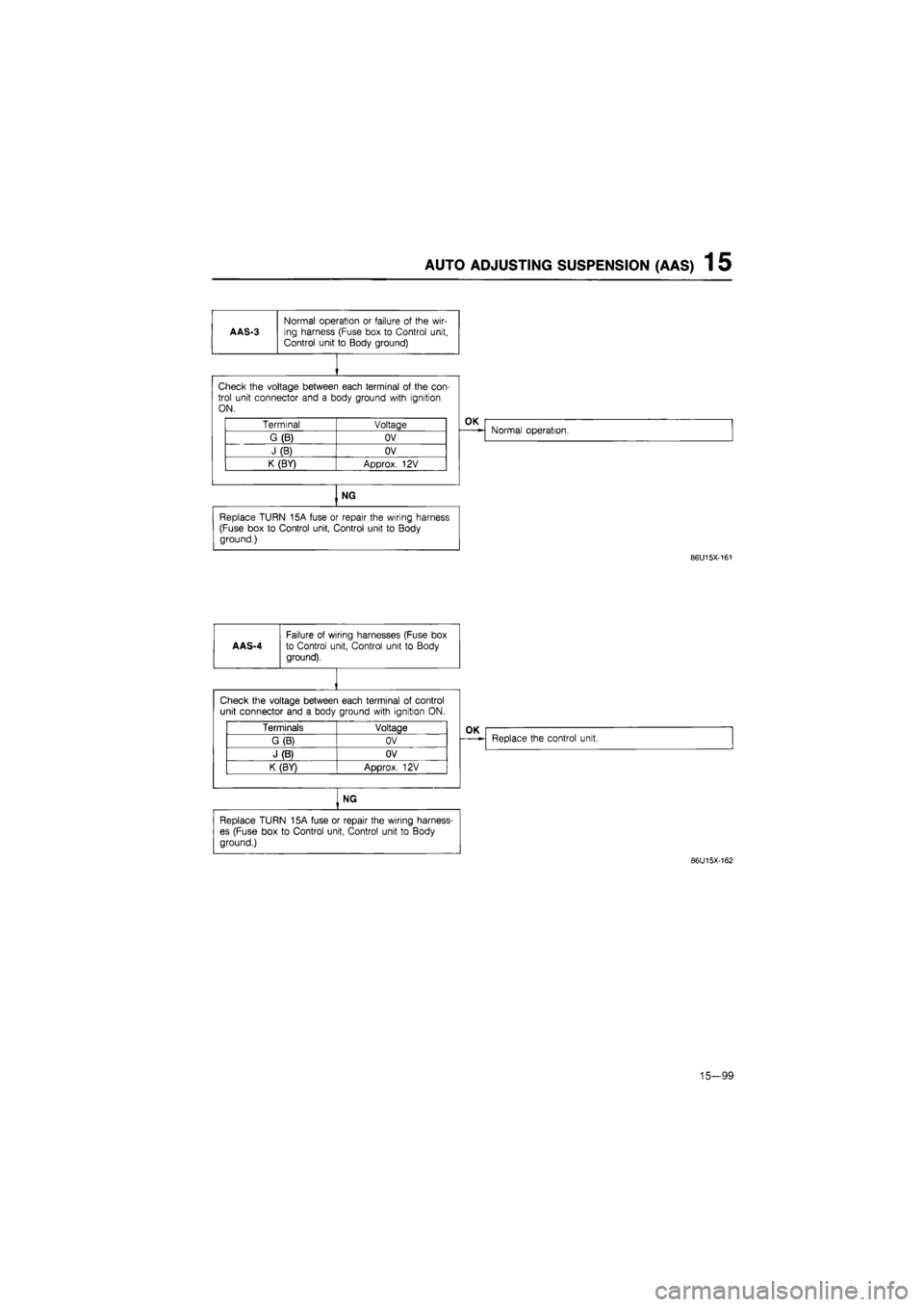
AAS-3
Normal operation
or
failure
of
the wir-ing harness (Fuse box
to
Control unit, Control unit
to
Body ground)
Check the voltage between each terminal
of
the con-trol unit connector and
a
body ground with ignition ON.
Terminal Voltage
G(B) OV
J(B) OV
K (BY) Approx.
12V
OK
Normal operation.
NG
Replace TURN 15A fuse
or
repair the wiring harness (Fuse box
to
Control unit, Control unit
to
Body ground.)
86U15X-161
AAS-4
Failure
of
wiring harnesses (Fuse
box
to Control unit, Control unit
to
Body
ground).
Check the voltage between each terminal
of
control unit connector and
a
body ground with ignition
ON.
Terminals Voltage
G (B) OV
J (B) OV
K (BY)
ADDTOX.
12V
OK
Replace the control unit.
NG
Replace TURN 15A fuse
or
repair the wiring harness-
es (Fuse box
to
Control unit, Control unit
to
Body
ground.)
86U15X-162
15-99
Page 1755 of 1865
1 5 AUTO ADJUSTING SUSPENSION (AAS)
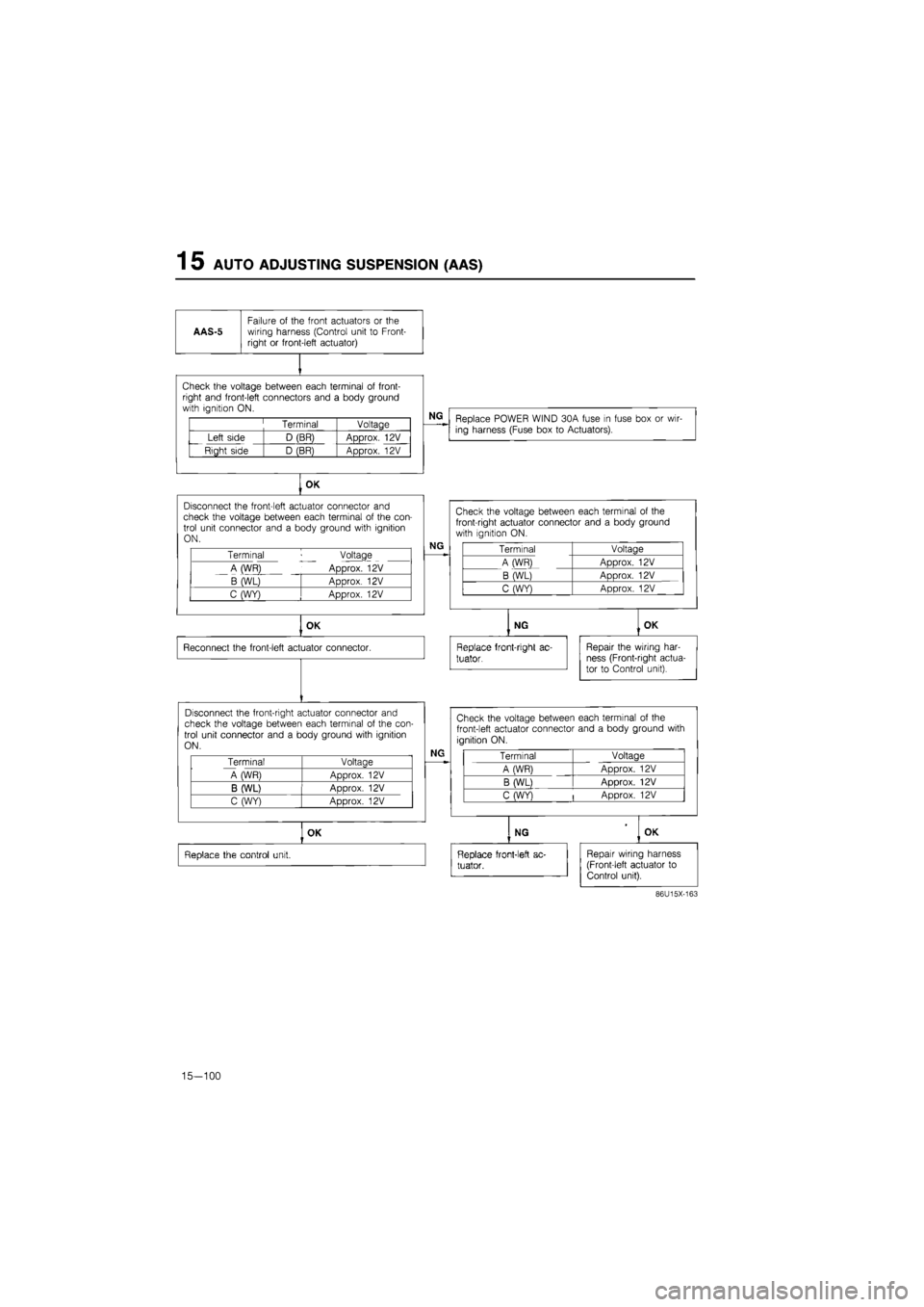
AAS-5
Failure
of
the front actuators
or the
wiring harness (Control unit
to
Front-right
or
front-left actuator)
Check the voltage between each terminal
of
front-right and front-left connectors and
a
body ground with ignition ON.
Terminal Voltage
Left side D (BR) Approx.
12V
Right side D (BR) Approx.
12V
NG
Replace POWER WIND 30A fuse
in
fuse box
or
wir-ing harness (Fuse box
to
Actuators).
OK
Disconnect the front-left actuator connector
and
check the voltage between each terminal
of
the con-trol unit connector and
a
body ground with ignition ON.
Terminal Voltage
A (WR) Approx.
12V
B (WL) Approx.
12V
C (WY) Approx.
12V
NG
OK
Reconnect the front-left actuator connector.
Disconnect the front-right actuator connector and check the voltage between each terminal
of
the con-trol unit connector and
a
body ground with ignition ON.
Terminal Voltage
A WR) Aoorox.
12V
B (WL) ADDrox.
12V
C (WY) Approx.
12V
Check the voltage between each terminal
of the
front-right actuator connector and
a
body ground with ignition
ON.
Terminal Voltage
A (WR) Approx.
12V
B (WL) Approx.
12V
C (WY) Approx.
12V
NG
Replace front-right
ac-
tuator.
OK
Repair the wiring har-ness (Front-right actua-tor
to
Control unit).
NG
Check the voltage between each terminal
of
the
front-left actuator connector and
a
body ground with
ignition ON.
Terminal Voltage
A (WR) Approx.
12V
B (WL) Approx.
12V
C (WY)
|
Approx.
12V
OK
Replace the control unit.
NG OK
Replace front-left
ac-
tuator.
Repair wiring harness (Front-left actuator
to
Control unit).
86U15X-163
15-100
Page 1756 of 1865
AUTO ADJUSTING SUSPENSION (AAS) 1 5
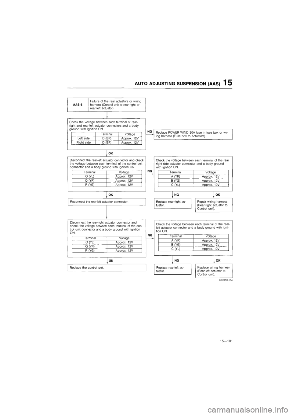
AAS-6
Failure
of
the rear actuators
or
wiring harness (Control unit
to
rear-right
or
rear-left actuator)
vi i11 1vuuuyu tw/v^ii I^CI^I i id i i in I«I wi i
right and rear-left actuator connectors and
a
body ground with ignition ON.
Terminal Voltage
Left side D (BR) Approx.
12V
Right side D (BR) Approx.
12V
NG
Replace POWER WIND 30A fuse
in
fuse box
or
wir-ing harness (Fuse box
to
Actuators).
OK
Disconnect the rear-left actuator connector and check the voltage between each terminal
of
the control unit connector and
a
body ground with ignition ON.
Terminal Voltage
0 (YL) Approx.
12V
Q (YR) Approx.
12V
R (YG) Approx.
12V
NG
OK
Reconnect the rear-left actuator connector.
Disconnect the rear-right actuator connector and check the voltage between each terminal
of
the con-trol unit connector and
a
body ground with ignition ON.
Terminal
'
Voltage
0 (YL)
ADDrox 12V
Q (YR)
ADDrox. 12V
R (YG} Approx.
12V
NG
OK
Replace the control unit.
Check the voltage between each terminal
of
the rear right side actuator connector and
a
body ground with ignition ON.
Terminal Voltage
A (YR) Approx.
12V
B (YG) Approx.
12V
C (YL) Approx.
12V
NG
Replace rear-right ac-
tuator,
OK
Repair wiring harness (Rear-right actuator
to
Control unit).
Check the voltage between each terminal
of
the rear-left actuator connector and
a
body ground with igni-tion ON.
Terminal Voltaae
A (YR) Approx.
12V
B (YG) ADDrox.
12V
C (YL) Approx.
12V
NG
Replace rear-1 eft
ac-
tuator.
OK
Replace wiring harness (Rear-left actuator
to
Control unit).
86U15X-164
15—101