1987 MAZDA 626 heating
[x] Cancel search: heatingPage 405 of 1865
![MAZDA 626 1987 Workshop Manual
4 A AUTO-RETURN CHOKE SYSTEM
AUTO-RETURN CHOKE SYSTEM
[FE 8VALVE—UNLEADED FUEL, MIDDLE EAST, and F6—GENERAL]
r ~ I
76G04A-066
An auto-return choke is adopted to prevent the catalytic convert MAZDA 626 1987 Workshop Manual
4 A AUTO-RETURN CHOKE SYSTEM
AUTO-RETURN CHOKE SYSTEM
[FE 8VALVE—UNLEADED FUEL, MIDDLE EAST, and F6—GENERAL]
r ~ I
76G04A-066
An auto-return choke is adopted to prevent the catalytic convert](/manual-img/28/57059/w960_57059-404.png)
4 A AUTO-RETURN CHOKE SYSTEM
AUTO-RETURN CHOKE SYSTEM
[FE 8VALVE—UNLEADED FUEL, MIDDLE EAST, and F6—GENERAL]
r ~ I
76G04A-066
An auto-return choke is adopted to prevent the catalytic converter from over-heating because of over
use of the choke. This system opens the choke valve by causing the choke knob to return when the
engine coolant temperature is more than 67°C (153°F).
TROUBLESHOOTING
Note
Make the system inspection first. If no problem is found, continue with the next inspec-
tion of the Troubleshooting Guide. (Refer to pages 4A—16, 21, or 22)
Possible cause
" ^ Page
Symptom
System inspection Choke magnet Water thermo switch
Possible cause
" ^ Page
Symptom 4A—40 4A—41 4A—41
Checking order 1 2 3
76G04A-067
System Inspection
1. Make sure that the engine is cold and turn the ig-
nition switch ON.
2. Pull out the choke knob and check that it is held on.
3. Start the engine and check that the choke knob
returns during warming-up.
76G04A-068
4A—40
Page 418 of 1865
![MAZDA 626 1987 Workshop Manual
DECELERATION CONTROL SYSTEM 4 A
SLOW FUEL CUT SYSTEM [FE 8VALVE—UNLEADED FUEL]
76G04A-096
This system shuts the primary slow fuel passage to prevent run-on and overheating of the exhaust
system MAZDA 626 1987 Workshop Manual
DECELERATION CONTROL SYSTEM 4 A
SLOW FUEL CUT SYSTEM [FE 8VALVE—UNLEADED FUEL]
76G04A-096
This system shuts the primary slow fuel passage to prevent run-on and overheating of the exhaust
system](/manual-img/28/57059/w960_57059-417.png)
DECELERATION CONTROL SYSTEM 4 A
SLOW FUEL CUT SYSTEM [FE 8VALVE—UNLEADED FUEL]
76G04A-096
This system shuts the primary slow fuel passage to prevent run-on and overheating of the exhaust
system when the ignition switch is turned OFF or during deceleration (engine speed above 2,300
rpm and idle switch ON). The slow fuel cut solenoid is actuated by the engine control unit and ignition
switch.
Troubleshooting
Note
Make the system inspection first. If no problem is found, continue with the next inspec-
tion of the Troubleshooting Guide. (Refer to page 4A—47.)
Possible cause System inspection Slow fuel cut solenoid valve
Page 4A—53 4A—34
Check order 1 2
System Inspection
1. Warm up the engine and run it at idle.
2. Connect a tachometer to the engine.
3. Connect a voltmeter to the carburetor connector
terminal (BW wire).
4. Increase the engine speed to 4,000 rpm; then re-
lease the throttle lever.
5. Measure the terminal voltage.
Engine speed Voltage
Above approx. 2,300 rpm Approx. 12V
Below approx. 2,300 rpm Below 1.5V
76G04A-097
4A-53
Page 469 of 1865

TROUBLESHOOTING GUIDE 4B
TROUBLESHOOTING GUIDE
This troubleshooting guide shows the malfunction numbers and the symptoms of various failures.
Perform troubleshooting as described below.
Possible cause
Symptom
Input sensors and switches
o>
C
0
Jh c 01
4B-14
a> 4)
E
o
4B-1S
o in c « m o E k_ 0) c.
0 <0 £
4B-16
o CO c a> 0) o E
a>
.x
co
4B-17
o 10 c a) co
4B-18
o in c a> (0
o> o> a>
a) £ a VI o E
4B-19
0 <0 c a> 0) c a> 01
S? o
4B-20
E a> in (0
o 10 A •o 0) 0> u.
4B-21
Output solenoid valves
o «
3 O) 0)
0) 0) 01
0> > 10 >
•o o c V o tt)
4B-22
0)
OI
0> > CO >
TJ
O c 0> o CO
4B-23
oc O u
o> > 75 >
•o o c a> o 05
4B-23
0 a. 3 1
2
0) > (0 >
"D O
o 0> in in a a >. £
4B-23
ffl a 3 • a>
2
a> > 10 >
"O o c a> o
CO Q. >. JO
4B-24
Fault Indicated by SST
Code No. 01 08 09 10 12 14 15 17 25 26 28 34 35
Hard start or won't start
(Cranks OK)
Engine stalls
Rough
idle
While warming up
After warming up
While warming up
After warming up
High idle speed after
warming up
TROUBLESHOOTING PROCEDURE
Note
Step 1 under symptom is to quickly determine what system or unit may be at fault by use of the SST. (Self-Diagnosis Checker 49 H018 9A1)
1st:
Check input sensors and output solenoid valves with the
SST.
(Refer
to
page 4B—10.)
2nd:
Check other switches with the
SST.
(Refer
to
page 4B—26.)
3rd:
Check the following items:
11
Poor acceleration, hesita-
tion or lack of power
Runs rough on deceleration
Afterburn in exhaust system
Poor fuel consumption
Engine stalls or rough after hot starting
Electrical system
1) Battery condition
2) Fuses
Fuel system
1) Fuel level 2) Fuel leakage
3) Fuel filter 4) Idle speed
Engine
1) Compression 2) Overheating
Ignition system
1) Ignition spark 2) Ignition timing
Intake air system
1)
Air
cleaner element 2) Vacuum
or air
leakage 3) Vacuum hose routing
4) Accelerator cable
Others
1) Clutch slippage 2) Brake dragging
Fails emission test 4th:
Check Fuel and Emission Control Systems. (Refer
to
page 4B—8.)
76G04B-003
4B—7
Page 570 of 1865

TROUBLESHOOTING GUIDE 4C
TROUBLESHOOTING GUIDE
This troubleshooting guide shows the malfunction numbers and the symptoms of various failures.
Perform troubleshooting as described below.
Input sensors and switches
Possible cause
Page
Symptom and No. CO
T O
a c OI '35
O
I o Tt
o in
a> in
8 c
o
o (A C 0) in
S o
I o
c $
o E
00 T-I O
T o I-ij
o in c at at o E « £
2 a
o>
o
e o •C H
I O
o at e 0)
o CM I o
E a> «-» in >• in a o (0 A •o a> d>
CM I o
Output solenoid valve
o> > <0 >
2
—.
§8 £ c
O O
(0
O
CVI I o
c 0 u « 01 w 3 a
o z «
> 73 >
"O o c a> o (/)
CM CM
o
O o 0) o>
Q. CM
V >
CB >
•o o c 4) o CO
CM CM
O
oc (9 UJ, g
n >
•o o c a> o <0
CO CM
O
o o •o w « a in «
2
s
5 •o o c »
o CO
CO CM
o
n
£
o in c a* (A c a> o>
o
CM
O
w q) t « s > c w QJ O)
"8 g> IS n « £
a> >
a >
T3 O C ai o CO
TT CM
o
Fault Indicated by SST
Code No. 02 03 05 *i 08 09 11 12 *2 15 • 2 17 *2 25 26 *2 27 *2 28 • 2 34 36 • 2 41
Hard start or won't start
(Cranks OK)
Engine stalls
Rough
Idle
During warm up
After warm up
During warm up
After warm up
High idle speed after warm up
Poor acceleration, hesita-tion or lack of power
TROUBLESHOOTING PROCEDURE
Note
Code No. Is to quickly determine which system or unit may be at fault by use of the SST. (Self-Diagnosis Checker 49 H018 9A1 or Digital Code Checker 49 G018 9A0 with Adaptor harness 49 9200 180)
1st: Check input sensors and output solenoid valves with the SST. (Refer to
page
AC—11.)
2nd: Check other switches with the SST. (Refer to page AC—25.)
3rd: Check the following items:
Electrical system
1) Battery condition 2) Fuses
Runs rough on deceleration
Afterburn in exhaust
system
9
10
Poor fuel consumption
Engine stalls or runs
rough after hot starting
11
12
Knocking
Fuel system
1) Fuel level
2) Fuel leakage 3) Fuel filter 4) Idle speed (with test connec-tor grounded)
Engine
1) Compression 2) Overheating
Ignition system 1) Ignition spark
2) Ignition timing (with test connec-tor grounded)
Intake air system 1) Air cleaner element 2) Vacuum or air leakage 3) Vacuum hose routing 4) Accelerator cable
Others 1) Clutch slippage
2) Brake dragging
Fails emission test 4th: Check Fuel and Emission Control Systems. (Refer to page 4C—10.)
*1..
*2„
.Leaded fuel
.Unleaded fuel
76G04C-009
4C—9
Page 715 of 1865

SPARK PLUG 5
Slow Charge
1. Stop the engine
2. Turn all the accessories off.
3. Remove the negative battery cable.
4. Perform a slow charge (3.5A to 4.5A).
5. Add distilled water if necessary while charging.
6. Charge once more if the specific gravity is under
fully charged gravity.
4BG05X-010
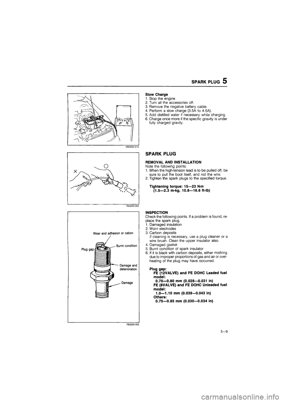
SPARK PLUG
REMOVAL AND INSTALLATION
Note the following points:
1. When the high-tension lead is to be pulled off, be
sure to pull the boot itself, and not the wire.
2. Tighten the spark plugs to the specified torque.
Tightening torque: 15—23 N-m
(1.5—2.3 m-kg, 10.8—16.6 ft-lb)
76G05X-054
Wear and adhesion or cabon
INSPECTION
Check the following points. If a problem is found, re-
place the spark plug.
1. Damaged insulation
2. Worn electrodes
3. Carbon deposits
If cleaning is necessary, use a plug cleaner or a
wire brush. Clean the upper insulator also.
4. Damaged gasket
5. Burnt condition of spark insulator
6. If it is black with carbon deposits, either misfiring
due to improper proportions of gas and air or over-
heating of the plug may have occurred.
Plug gap:
FE (12VALVE) and FE DOHC Leaded fuel
model:
0.70—0.80 mm (0.028—0.031 in)
FE (8VALVE) and FE DOHC Unleaded fuel
model:
1.0—1.10 mm (0.039—0.043 in)
Others:
0.75—0.85 mm (0.030—0.034 in)
76G05X-005
5-9
Page 783 of 1865

QUICK START SYSTEM (QSS) 5
SYSTEM OPERATION
The Quick Start System has three functions: Pre-heating, Chopping, and After-glow; as used in
the previous model. Each function operates as follows:
1. Pre-heating After ignition switch is turned to ON position, current flows to glow plug for 6
sec.
2. Chopping While engine switch is in START position, current flows to glow plug con-
tinuously.
3. After-glow (coolant temperature below 30°C (86°F):
a) When engine switch is kept in ON position after pre-heating, current flows to
glow plug continuously for 15 sec.
b) After engine has stared, current flows to glow plug continuously for 15 sec.
Indicator lamp: Indicator illuminates for 3 sec. after ignition is ON position.
When ignition switch is ON-START-ON position
When ignition switch is kept in ON position
76G05X-050
5-77
Page 1594 of 1865

SIDE
PROTECTOR MOLDING
1
4
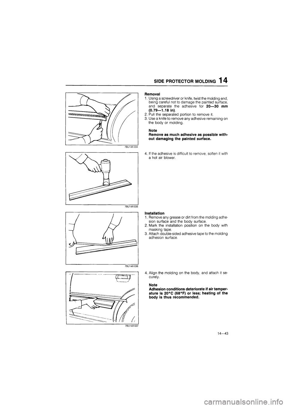
Removal
1. Using a screwdriver or knife, twist the molding end,
being careful not to damage the painted surface,
and separate the adhesive for 20—30 mm
(0.79—1.18 in).
2. Pull the separated portion to remove it.
3. Use a knife to remove any adhesive remaining on
the body or molding.
Note
Remove as much adhesive as possible with-
out damaging the painted surface.
7BU14X-034
7BU14X-035
7BU14X-036
4. If the adhesive is difficult to remove, soften it with
a hot air blower.
Installation
1. Remove any grease or dirt from the molding adhe-
sion surface and the body surface.
2. Mark the installation position on the body with
masking tape.
3. Attach double-sided adhesive tape to the molding
adhesion surface.
4. Align the molding on the body, and attach it se-
curely.
Note
Adhesion conditions deteriorate if air temper-
ature is 20°C (68°F) or less; heating of the
body is thus recommended.
7BU14X-037
14—43
Page 1786 of 1865

OUTLINE 16
The air distribution is shown in the figure.
"I.The door (D1) is used to select either fresh air from outside or recirculated air. Setting the
RECIRC/FRESH control lever (switch) to the FRESH position will allow outside air to come inside.
Setting the RECIRC/FRESH control lever (switch) to the RECIRC position will allow inside air to recir-
culate.
2. Outlet airflow is controlled by doors D3, D4, D5.
Moving (pushing) the mode control lever (switch) opens and shuts the doors (D3, D4, D5) and cre-
ates the air passage according to the lever position.
1) Setting the lever to the VENT position (push the VENT switch) creates the air passage to the venti-
lator outlets, and air comes into the passenger compartment from the ventilator outlets.
2) Setting the lever to the BI-LEVEL position (push the BI-LEVEL switch) creates the air passage
to the ventilator outlets and to the floor outlets.
3) Setting the lever to the HEAT position (push the HEAT switch) creates the air passage to the floor
outlets.
(A little air comes from the defroster outlets.)
4) Setting the lever to the DEF/HEAT position (push the DEF/HEAT switch) creates the air passage
to the floor outlets and to the defroster outlets.
5) Setting the lever to the DEF position (push the DEF switch) creates the air passage to the defroster
outlets.
3. The cooling or heating temperature is controlled by doors D2.
76G16X-002
16-3